guidline for practice - Glynwed Asia
guidline for practice - Glynwed Asia
guidline for practice - Glynwed Asia

You also want an ePaper? Increase the reach of your titles
YUMPU automatically turns print PDFs into web optimized ePapers that Google loves.
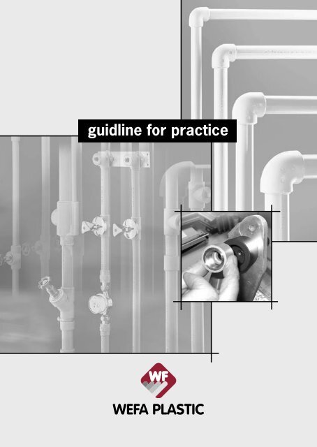
<strong>guidline</strong> <strong>for</strong> <strong>practice</strong><br />
1
Content<br />
1 The Pipe System Page 4 - 10<br />
2 System quality<br />
Page 12 - 13<br />
3 Product range Page 14 - 37<br />
4 Welding and processing techniques Page 38 - 49<br />
5 Hints on installation Page 50 - 65<br />
6 Planning and design Page 66 - 67<br />
7 Hotlines Page 68 - 69<br />
3
Permissible operational overpressures<br />
The pipe system<br />
Permissible operational pressures <strong>for</strong> pipes consisting of PP-R 100,<br />
<strong>for</strong> water Safety factor (SF) = 1,25, DIN 8077: 1999-07<br />
Temperature Operating years PN10 PN16 PN20 PN25<br />
Diameter wall thickness SDR<br />
11 7,4 6 5<br />
Permissible operational pressure<br />
10 1 21,1 33,4 42,0 52,9<br />
5 20,0 31,6 39,8 50,1<br />
10 19,3 30,6 38,5 48,5<br />
25 18,7 29,6 37,3 46,9<br />
50 18,2 28,8 36,3 45,7<br />
100 17,7 28,1 35,4 44,5<br />
20 1 18,0 28,6 36,0 45,3<br />
5 16,9 26,8 33,8 42,5<br />
10 16,4 26,1 32,8 41,3<br />
25 16,0 25,3 31,8 40,1<br />
50 15,5 24,5 30,9 38,9<br />
100 15,0 23,8 29,3 37,7<br />
30 1 15,3 24,3 30,6 38,5<br />
5 14,4 22,8 28,7 36,1<br />
10 13,9 22,0 27,7 34,9<br />
25 13,4 21,3 26,8 33,7<br />
50 13,1 20,7 26,1 32,9<br />
100 12,8 20,2 25,5 32,1<br />
40 1 12,9 20,5 25,8 32,5<br />
5 12,1 19,2 24,2 30,5<br />
10 11,8 18,7 23,6 29,7<br />
25 11,3 18,0 22,6 28,5<br />
50 11,0 17,5 22,0 27,7<br />
100 10,7 16,9 21,3 26,9<br />
50 1 11,0 17,5 22,0 27,7<br />
5 10,2 16,2 20,4 25,7<br />
10 9,9 15,7 19,7 24,9<br />
25 9,6 15,2 19,1 24,1<br />
50 9,3 14,7 18,5 23,3<br />
100 8,9 14,2 17,8 22,5<br />
60 1 9,3 14,7 18,5 23,3<br />
5 8,6 13,7 17,2 21,7<br />
10 8,3 13,2 16,6 20,8<br />
25 8,0 12,6 15,9 20,0<br />
50 7,7 12,1 15,3 19,2<br />
70 1 7,8 12,4 15,6 19,6<br />
5 7,2 11,4 14,3 18,0<br />
10 7,0 11,1 14,0 17,6<br />
25 6,1 9,6 12,1 15,2<br />
50 5,1 8,1 10,2 12,8<br />
80 1 6,5 10,4 13,1 16,4<br />
5 5,7 9,1 11,5 14,4<br />
10 4,8 7,6 9,6 12,0<br />
25 3,8 6,1 7,6 9,6<br />
95 1 4,6 7,3 9,2 11,6<br />
5 3,0 4,8 6,1 7,6<br />
10 2,6 4,0 5,1 6,4<br />
4
Permissible operational overpressures<br />
Permissible operational pressures <strong>for</strong> hot water and<br />
central heating systems<br />
Heating period Temperature Operating years Safety factor = 1,25<br />
Continous<br />
working<br />
temperature<br />
70 °C<br />
incl. 60 Days<br />
per year with<br />
WEFATHERM<br />
Pipe PN 20<br />
WEFATHERM<br />
Stabi-Pipe PN 20<br />
WEFATHERM<br />
Fiber pipe<br />
PN 20<br />
Permissible operational pressure<br />
SDR 6 SDR 7,4 SDR 5<br />
WEFATHERM<br />
Stabi-Pipe<br />
PN 25<br />
75 °C 5 14,30 11,40 15,90<br />
10 13,70 10,90 14,50<br />
25 11,80 9,30 13,70<br />
45 10,40 8,10 12,80<br />
80 °C 5 12,90 10,07 15,80<br />
10 12,20 9,70 15,40<br />
25 10,70 8,60 13,20<br />
40 9,80 7,80 11,60<br />
85 °C 5 12,51 9,94 15,78<br />
10 11,90 9,50 15,30<br />
25 9,70 7,80 13,20<br />
35 8,90 7,10 11,20<br />
90 °C 5 11,80 9,37 14,90<br />
10 10,30 8,40 12,90<br />
25 8,40 6,60 10,48<br />
30 7,63 6,30 8,45<br />
The pipe system<br />
Continous<br />
working<br />
temperature<br />
70 °C<br />
incl. 90 Days<br />
per year with<br />
75 °C 5 13,95 11,50 14,73<br />
10 13,40 10,80 13,80<br />
25 11,50 9,20 12,40<br />
45 8,90 7,00 11,20<br />
80 °C 5 12,75 10,14 16,10<br />
10 12,33 9,81 15,50<br />
25 10,06 8,02 12,71<br />
37,5 9,15 7,27 11,52<br />
85 °C 5 12,00 9,54 15,15<br />
10 11,29 9,00 14,20<br />
25 9,62 7,63 12,16<br />
32,5 9,07 7,20 11,40<br />
90 °C 5 10,79 8,60 11,30<br />
10 9,30 7,41 10,45<br />
25 7,35 5,73 9,22<br />
* SDR = Standard Dimension Ratio (Diameter-/Wall thickness)<br />
5
Drinking water systems<br />
The pipe system<br />
By reason of its special material properties and chemical resistance,<br />
WEFATHERM pipe systems can be used <strong>for</strong> a wide range of<br />
areas of application including systems <strong>for</strong> drinking water and water<br />
<strong>for</strong> other purposes in houses and residential buildings, offices,<br />
schools, hotels, hospitals, ships etc. Agriculture and horticulture,<br />
compressed air systems, heat distribution systems, heat generation<br />
connections, distribution connections, floor distribution systems,<br />
rising mains, industrial pipe networks, the foodstuffs industry.<br />
Systematic distribution from the housewater connection up to...<br />
consumer points in the bathroom.<br />
6
Drinking water systems<br />
The WEFATHERM pipe system offers great advantages by reason of<br />
the fact that joints are produced by polyfusion welding, problemfree,<br />
flamefree even in the case of renovation work.<br />
Thanks to the well thought out system, many different types of<br />
system can be realized rapidly and reliably: rising mains, floor<br />
distribution systems, connection of rising mains to floor distribution<br />
systems, surface and buried installation, on-wall mounting, heat<br />
distribution systems.<br />
The WEFATHERM pipe system<br />
with its components makes<br />
possible complete installations<br />
from the rising main via the<br />
connection point to floor distribution<br />
systems ...<br />
The pipe system<br />
... to be realized up to the consumer<br />
points, whether these<br />
be buried or surface mounted,<br />
with one material in an environmentally<br />
friendly and reliable<br />
manner.<br />
7
Heating and airconditioning systems<br />
The WEFATHERM pipe system with its components enables transitions<br />
to existing systems in other materials to be achieved in a<br />
problemfree manner without any compromises. Polypropylene is<br />
corrosionfree and resistant to thermal aging. In addition it gives<br />
no opportunity <strong>for</strong> deposits to <strong>for</strong>m. Flow noises are damped to a<br />
large extent.<br />
The pipe system<br />
As result of the low heat conducting capacity of PP-R pipe systems<br />
isolation can be neglected, i.e. PPR pipes <strong>for</strong> KW-conduction do not<br />
need any isolation.<br />
The low heat conducting capacity<br />
of polypropylene almost totally<br />
prevents the appearance of<br />
condensed water at the outside<br />
part of the pipe.<br />
• PP 0,24<br />
• PE 0,35<br />
• Fe 50<br />
• Cu 400<br />
W/mK<br />
W/mK<br />
W/mK<br />
W/mK<br />
Please note:<br />
The legal regulations of the specific<br />
countries have to be taken<br />
into consideration.<br />
8
The WEFATHERM pipe system/components<br />
The WEFATHERM pipe and the WEFATHERM Stabi-Pipe are two components<br />
well adjusted to their practica application. With help of the<br />
molded parts they can be optima connected, even in the transition<br />
to fittings or pipe systems of other materials.<br />
The advantages in application of our new developed WEFATHERM<br />
Fiber-Pipe are low longitudinal expansion exposition (75 % less),<br />
higher circulation with maximum flow capacity, higher pipe<br />
stiffness as well as simple treadment without additional peeling<br />
process.<br />
A pipe of the new generation <strong>for</strong> every application.<br />
In drinking water installations from the house connection<br />
point or from the house connection distribution station up to the<br />
last consumer point, in heating installations from the boiler or waterheating<br />
unit up to the individual radiators or heat exchangers: in both<br />
areas each pipe system has precisely the right components. In all<br />
areas of application the material polypropylene and the WEFATHERM<br />
pipe system captivate with their freedom from corrosion and high<br />
resistance to the <strong>for</strong>ming of deposits, so that long service lives can<br />
be expected. Flow noises are damped so that systems are more<br />
user friendly than ones based on metallic materials.<br />
The pipe system<br />
9
The WEFATHERM pipe system/components<br />
The pipe system<br />
In cold water application the WEFATHERM pipe system is suitable.<br />
In hot water application the use of the WEFATHERM Stabi-Pipe is<br />
always advisable which is covered by an aluminium coat resulting<br />
in a reduced longitudinal expansion with heat load. Alternatively<br />
also the WEFATHERM Fiber-Pipe can be inserted now. Spans can<br />
be enlarged thus saving fastening cramps. Being impermeable to<br />
light is prevents the appearance of algas. The socket heat welding<br />
process requires only shortest processing and cooling times so<br />
that the system after processing is in very fast working condition.<br />
Waiting times are minimized.<br />
10
Free or surface mounting<br />
The system consists of 100% plastic and aluminium-plastic compound<br />
pipes, which are complemented and connected with fittings<br />
such as collar bush flange connections, shut-off valves, transition<br />
unions from metal to PP and from PP to metal, fitting connections<br />
and accessories. The chapter „Product overview“ shows in a clear<br />
manner the products which you need. The guarantee <strong>for</strong> our products<br />
is just as much a matter of course <strong>for</strong> us as our product liability,<br />
Quality checks are carried out regularly by external bodies such<br />
as the DVGW while in addition we carry out our own regular internal<br />
checks. Comprehensive planning and tender-preparation documents<br />
are available to facilitate your work.<br />
Quality<br />
Further in<strong>for</strong>mation on the themes of quality, certificates and tests<br />
is provided on page 12.<br />
The pipe system<br />
Protection against fire and noise<br />
Users often find flow noise disturbing. Such noise is however considerably<br />
reduced when the material is polypropylene. Metallic<br />
materials often transmit noise that is an order of magnitude greater.<br />
Fire protection is regulated in accordance with national regulations.<br />
Building authorities and fire protection officers will provide in<strong>for</strong>mation<br />
on this. WEFATHERM pipes and fittings fulfill the requirements<br />
of fire class B 2, i.e. they are classified as normally inflammable.<br />
Where a pipe system passes through structural parts of a building,<br />
steps must betaken that the required fire resistance capabilities are<br />
restored following installation.<br />
11
External monitorin / Test certificates<br />
The WEFATHERM pipe system is regularly checked by neutral,<br />
independent institutes. The monitoring is carried out by the South-<br />
German Plastics Centre (SKZ), Würzburg and TZW Karlsruhe. These<br />
are authorized as testing institutes by -- amongst other institutions<br />
-- the DVGW (German Association of the Gas and Water Profession).<br />
Analogous checks are carried out abroad. The results of these<br />
checks are passed on to Messrs. WEFA PLASTIC and documented<br />
in test certificates.<br />
System quality<br />
DVGW<br />
DW-8501AT2336<br />
(’TS 016)<br />
DVGW<br />
DW-8201AU2132<br />
DVGW<br />
DW-8501AU2354<br />
DVGW<br />
DW-8206AU2133<br />
12
International approvals WEFA PLASTIC<br />
System quality<br />
13
Wefatherm Pipe SDR 11<br />
Areas of application: cold-water systems/air conditioning<br />
rainwater lines<br />
Material: PP-R 100<br />
Pressure stage: PN 10 – SDR 11<br />
Pipe series: 4<br />
To DIN: 8077/78<br />
Delivery <strong>for</strong>m: in lengths à 4 m<br />
Colour:<br />
grey or green<br />
see table „Permissible operational overpressures” page 4, SDR 11.<br />
di<br />
d<br />
20052 to 20059<br />
Product range<br />
Pipe data Diameter Wall Internal Water Pipe<br />
thickness diameter ontent weight<br />
Art. No. Dimension LE d mm s mm di mm I/m kg/m DN<br />
20052 32 x 2,9 mm 40 32 2,9 26,0 0,531 0,267 25<br />
20053 40 x 3,7 mm 40 40 3,7 32,6 0,834 0,412 32<br />
20054 50 x 4,6 mm 20 50 4,6 40,8 1,307 0,638 40<br />
20055 63 x 5,8 mm 20 63 5,8 51,4 2,075 1,010 50<br />
20056 75 x 6,8 mm 12 75 6,8 61,2 2,941 1,420 60<br />
20057 90 x 8,2 mm 12 90 8,2 73,6 4,254 2,030 65<br />
20058 110 x 10,0 mm 8 110 10,0 90,0 6,362 3,010 80<br />
20059 125 x 11,4 mm 4 125 11,4 102,2 8,199 3,900 100<br />
Articel-No. with G = green<br />
14
Wefatherm Pipe SDR 6<br />
Areas of application: hot and cold water installation<br />
central heating systems air conditioning<br />
Material: PP-R 100<br />
Pressure stage: PN 20 – SDR 6<br />
Pipe series: 6<br />
To DIN: 8077/78<br />
Delivery <strong>for</strong>m: in lengths à 4 m / coils<br />
Colour:<br />
grey or green<br />
see table „Permissible operational overpressures” page 4 SDR 6.<br />
di<br />
d<br />
20001 to 20011<br />
Pipe data Diameter Wall Internal Water Pipe<br />
thickness diameter ontent weight<br />
Art. No. Dimension LE d mm s mm di mm I/m kg/m DN<br />
20001 16 x 2,7 mm 100 16 2,7 10,6 0,088 0,105 10<br />
20002 20 x 3,4 mm 100 20 3,4 13,2 0,137 0,161 12<br />
20003 25 x 4,2 mm 100 25 4,2 16,6 0,216 0,250 15<br />
20004 32 x 5,4 mm 40 32 5,4 21,2 0,353 0,410 20<br />
20005 40 x 6,7 mm 40 40 6,7 26,6 0,556 0,635 25<br />
20006 50 x 8,3 mm 20 50 8,3 33,2 0,866 0,995 32<br />
20007 63 x 10,5 mm 20 63 10,5 42,0 1,385 1,570 40<br />
20008 75 x 12,5 mm 12 75 12,5 50,0 1,963 2,230 50<br />
20009 90 x 15,0 mm 12 90 15,0 60,0 2,827 3,360 60<br />
20010 110 x 18,3 mm 8 110 18,3 73,2 4,208 5,040 65<br />
20011 125 x 20,8 mm 4 125 20,8 83,4 5,460 6,470 85<br />
Product range<br />
available in coils:<br />
20015 16 x 2,7 mm 100 16 2,7 10,6 0,088 0,105 10<br />
20016 20 x 3,4 mm 100 20 3,4 13,2 0,137 0,161 12<br />
20017 25 x 4,2 mm 100 25 4,2 16,6 0,216 0,250 15<br />
Articel-No. with G = green<br />
15
Wefatherm Stabi-Pipe SDR 6<br />
Areas of application: hot and cold water installation<br />
central heating systems<br />
Material:<br />
PP-R 100 in combination with aluminium<br />
Pressure stage: PN 20 – SDR 6<br />
Delivery <strong>for</strong>m: in lengths à 4 m<br />
Colour:<br />
grey or green<br />
Mechanically stabilized by means of integrated combination<br />
with aluminium<br />
see table „Permissible operational overpressures“ page 4 and 5, SDR 6.<br />
Sg<br />
d i<br />
d d g<br />
Product range<br />
S<br />
20300 to 20310<br />
Pipe data Diameter Wall Internal. d S Water Pipe<br />
thickness Diam. compl. compl. content weight<br />
Art. No. Dimension LE d mm s mm di mm dg Sg I/m kg/m DN<br />
20300 16 x 2,2 mm 100 16 2,2 11,6 17,6 3,0 0,102 0,145 12<br />
20301 20 x 2,8 mm 100 20 2,8 14,4 21,6 3,6 0,163 0,192 15<br />
20302 25 x 3,5 mm 100 25 3,5 18,0 26,8 4,4 0,254 0,297 20<br />
20303 32 x 4,4 mm 40 32 4,4 23,2 33,8 5,4 0,415 0,456 25<br />
20304 40 x 5,5 mm 40 40 5,5 29,0 42,0 6,6 0,615 0,679 32<br />
20305 50 x 6,9 mm 20 50 6,9 36,2 52,0 7,9 1,029 1,044 40<br />
20306 63 x 8,6 mm 20 63 8,6 45,8 65,0 9,7 1,633 1,576 50<br />
20307 75 x 10,3 mm 20 75 10,3 54,4 77,0 11,4 2,307 2,197 60<br />
20308 90 x 12,3 mm 08 90 12.3 65,4 92,0 13,5 3,318 3,230 65<br />
20309 110 x 15,1 mm 8 110 15,1 79,8 113,0 16,7 5,674 4,875 80<br />
20310 125 x 17,1 mm 4 125 17,1 90,8 129,0 19,1 6.472 5.930 90<br />
available in coils:<br />
20314 16 x 2,2 mm 100 16 2,2 11,6 17,6 3,0 0,102 0,145 12<br />
available in coils / colour white / Aluminium without per<strong>for</strong>ation:<br />
20317 16 x 2,2 mm 100 16 2,2 11,6 17,6 3,0 0,102 0,145 12<br />
Article no, with G= green<br />
For pipes diameter 16mm, internal pipe support Article No. 20311 is recommended<br />
16
Wefatherm Stabi-Pipe SDR 6/UV<br />
Areas of application: external hot and cold water installations<br />
central heating systems<br />
Pressure stage: PP-R 100 in combination with Aluminium<br />
Pressure stage: PN 20 – SDR 6<br />
Delivery <strong>for</strong>m: in lengths à 4 m<br />
Colour:<br />
black<br />
Mechanically stabilized by means of integrated combination<br />
with aluminium external Layer UV-stabilized<br />
see table „Permissible operational overpressures“ page 4 and 5, SDR 6/UV.<br />
Sg<br />
di<br />
d d g<br />
S<br />
Pipe data Diameter Wall Internal. d S Water Pipe<br />
thickness Diam. compl. compl. content weight<br />
Art. No. Dimension LE d mm s mm di mm dg Sg I/m kg/m DN<br />
20370 20 x 2,8 mm 100 20 2,8 14,4 21,6 3,6 0,163 0,192 15<br />
20371 25 x 3,5 mm 100 25 3,5 18,0 26,8 4,4 0,254 0,297 20<br />
20372 32 x 4,4 mm 40 32 4,4 23,2 33,8 5,4 0,415 0,456 25<br />
20373 40 x 5,5 mm 40 40 5,5 29,0 42,0 6,6 0,615 0,679 32<br />
20374 50 x 6,9 mm 20 50 6,9 36,2 52,0 7,9 1,029 1,044 40<br />
20375 63 x 8,6 mm 20 63 8,6 45,8 65,0 9,7 1,633 1,576 50<br />
20376 75 x 10,3 mm 20 75 10,3 54,4 77,0 11,4 2,307 2,197 60<br />
Product range<br />
17
Wefatherm Fiber-Pipe SDR 7,4<br />
Areas of application: hot and cold water installation,<br />
central heating systems<br />
Material:<br />
PP-R 100 in compound<br />
Pressure stage: PN 20 – SDR 7,4<br />
Delivery <strong>for</strong>m: in Stangen à 4 m<br />
Delivery units: in meters<br />
Colour:<br />
grey or green<br />
Mechanically stabilized by fiber compound mixture in the<br />
middle layer of material PP-R 80<br />
Identification mark: 4 red stripes<br />
The relationship between application temperature, pressure load an years of operation is<br />
shown in table 3, respectively table 4 (Page 4 and 5).<br />
Product range<br />
Pipe data Diameter Wall Internal. Water Pipe<br />
thickness compl. content weight<br />
Art. No. Dimension LE d mm s mm di mm I/m kg/m DN<br />
20150 20 x 2,8 mm 100 20 2,8 14,4 0,163 0,156 15<br />
20151 25 x 3,5 mm 100 25 3,5 18,0 0,254 0,237 20<br />
20152 32 x 4,4 mm 40 32 4,4 23,2 0,415 0,380 25<br />
20153 40 x 5,5 mm 40 40 5,5 29,0 0,615 0,607 32<br />
20154 50 x 6,9 mm 20 50 6,9 36,2 1,029 0,901 40<br />
20155 63 x 8,6 mm 20 63 8,6 45,8 1,633 1,440 50<br />
20156 75 x 10,3 mm 20 75 10,3 54,4 2,307 2,090 50<br />
20157 90 x 12,3 mm 12 90 12,3 65,4 3,318 2,983 65<br />
20158 110 x 15,1 mm 8 110 15,1 79,8 5,674 4,387 80<br />
20159 125 x 17,1 mm 4 125 17,1 90,8 6,472 5,580 90<br />
18<br />
Article no. with G = green
Wefatherm Fiber-compond-Pipe ...<br />
... the newest Generation!<br />
In cooperation with the plastic laboratoy of the group WEFAPLASTIC<br />
has developed a new compound representing a revolutionary<br />
improvement in the area of PP-R systems.<br />
• No bending after installation<br />
• Professional work guaranteed<br />
• High flow rate!<br />
• 20% higher flow rate with<br />
fiber pipe SDR 7.4/PN20<br />
• No UV transparency!<br />
• No grow of algae<br />
• No grow of bacteria´s<br />
• Hygienic approved<br />
• High temperature resistance!<br />
• Higher temperature resistance<br />
as plain pipe<br />
• Higher pressure resistance<br />
as plain pipe<br />
• More safety<br />
• Economical solution!<br />
– Just cut and weld<br />
Comparison to copper pipes / compound pipes<br />
Flow value V (l/s) in dependence<br />
of flow rate v (m/s)<br />
Copper pipes according to DIN 1786<br />
Dimension d i<br />
V max<br />
(l/s)<br />
(mm) v = 2,5 m/s<br />
Compound pipes PN 20/SDR 7,4<br />
Dimension/ d i<br />
V max<br />
(l/s)<br />
(mm) v = 2,5 m/s<br />
Product range<br />
18,0 x 1,0 mm 16,0 0,50<br />
22,0 x 1,0 mm 20,0 0,80<br />
28,0 x 1,5 mm 25,0 1,25<br />
35,0 x 1,5 mm 32,0 2,00<br />
42,0 x 1,5 mm 39,0 3,00<br />
54,0 x 2,0 mm 50,0 5,00<br />
64,0 x 2,0 mm 60,0 7,20<br />
76,1 x 2,0 mm 72,1 10,00<br />
88,9 x 2,0 mm 84,9 14,00<br />
20 x 2,8 mm 14,4 0,40<br />
25 x 3,5 mm 18,0 0,65<br />
32 x 4,4 mm 23,0 1,00<br />
40 x 5,5 mm 28,8 1,60<br />
50 x 6,9 mm 36,2 2,55<br />
63 x 8,6 mm 45,6 4,10<br />
75 x 10,3 mm 54,2 5,75<br />
90 x 12,3 mm 65,0 8,30<br />
110 x 15,1 mm 79,6 12,00<br />
125 x 17,1 mm 90,8 15,50<br />
19
Fittings<br />
Art-No. Unit Dimension Art.-Name Type<br />
20311 10 16 x 2,2 mm WEFATHERM<br />
Pipe support case <strong>for</strong> pipe<br />
20500 10 16 mm WEFATHERM<br />
20501 10 20 mm Overbridge-bow<br />
20502 10 25 mm<br />
20503 10 32 mm<br />
20600 1 Ø 25–4 x 16 WEFATHERM<br />
20602 1 Ø 32–4 x 20 Manifold distributor<br />
20604 1 Ø 32–4 x 1/2” IG Manifold<br />
20606 1 Ø 40–4 x 1/2” IG with inside thread<br />
20608 1 Ø 32–4 x 1/2” AG Manifold<br />
20610 1 Ø 40–4 x 1/2” AG with outside thread<br />
Product range<br />
21100 10 16 mm WEFATHERM<br />
21101 10 20 mm Long bend 90°<br />
21102 10 25 mm welding socket<br />
21103 10 32 mm on both sides<br />
21104 10 40 mm<br />
21001 10 16 mm WEFATHERM<br />
21002 10 20 mm Angle 90°<br />
21003 10 25 mm<br />
21004 10 32 mm<br />
21005 5 40 mm<br />
21006 5 50 mm<br />
21007 1 63 mm<br />
21008 1 75 mm<br />
21009 1 90 mm<br />
21010 1 110 mm<br />
21011 1 125 mm<br />
22000 10 16 mm i./a. WEFATHERM<br />
22001 10 20 mm i./a. Angle 90°<br />
22002 10 25 mm i./a. female / male<br />
22003 10 32 mm i./a.<br />
20<br />
Article no. with G = green
Fittings<br />
Art-No. Unit Dimension Art.-Name Type<br />
22100 10 20 mm WEFATHERM<br />
22101 10 25 mm Angle 45°<br />
22102 5 32 mm female / male<br />
23001 10 16 mm WEFATHERM<br />
23002 10 20 mm Angle 45°<br />
23003 10 25 mm<br />
23004 10 32 mm<br />
23005 5 40 mm<br />
23006 5 50 mm<br />
23007 1 63 mm<br />
23008 1 75 mm<br />
23009 1 90 mm<br />
23010 1 110 mm<br />
23011 1 125 mm<br />
24001 10 16 mm WEFATHERM<br />
24002 10 20 mm T-piece 90°<br />
24003 10 25 mm<br />
24004 10 32 mm<br />
24005 5 40 mm<br />
24006 5 50 mm<br />
24007 1 63 mm<br />
24008 1 75 mm<br />
24009 1 90 mm<br />
24010 1 110 mm<br />
24011 1 125 mm<br />
Product range<br />
Article no. with G = green<br />
21
Fittings<br />
Art-No. Unit Dimension Art.-Name Type<br />
Product range<br />
I II III WEFATHERM<br />
25001 10 20 x 16 x 20 T-piece 90°,<br />
25002 10 25 x 16 x 25 red.<br />
25003 10 25 x 20 x 25<br />
25004 10 32 x 20 x 32<br />
25005 10 32 x 25 x 32<br />
25006 5 40 x 20 x 40<br />
25007 5 40 x 25 x 40<br />
25008 5 40 x 32 x 40<br />
25009 5 50 x 25 x 50<br />
25010 5 50 x 32 x 50<br />
25011 5 50 x 40 x 50<br />
25012 1 63 x 20 x 63<br />
25013 1 63 x 25 x 63<br />
25014 1 63 x 32 x 63<br />
25015 1 63 x 40 x 63<br />
25016 1 63 x 50 x 63<br />
25017 1 75 x 20 x 75<br />
25018 1 75 x 25 x 75<br />
25019 1 75 x 32 x 75<br />
25020 1 75 x 40 x 75<br />
25021 1 75 x 50 x 75<br />
25022 1 75 x 63 x 75<br />
25023 10 32 x 32 x 25<br />
25024 10 25 x 20 x 20<br />
25025 10 20 x 25 x 25<br />
25026 10 32 x 20 x 25<br />
25028 10 32 x 25 x 25<br />
25032 1 90 x 63 x 90<br />
25033 1 90 x 75 x 90<br />
25034 1 110 x 63 x 110<br />
25035 1 110 x 75 x 110<br />
25036 1 110 x 90 x 110<br />
25037 1 125 x 75 x 125<br />
25038 1 125 x 90 x 125<br />
25039 1 125 x 110 x 125<br />
I<br />
III<br />
II<br />
Article no. with G = green<br />
22
Fittings<br />
Art-No. Unit Dimension Art.-Name Type<br />
26001 10 20 / 16 WEFATHERM<br />
26002 10 25 / 16 Red piece<br />
26003 10 25 / 20<br />
26004 10 32 / 20<br />
26005 10 32 / 25<br />
26006 5 40 / 20<br />
26007 5 40 / 25<br />
26008 5 40 / 32<br />
26009 5 50 / 20<br />
26010 5 50 / 25<br />
26011 5 50 / 32<br />
26012 5 50 / 40<br />
26013 1 63 / 40<br />
26014 1 63 / 25<br />
26015 1 63 / 32<br />
26016 1 63 / 50<br />
26017 1 75 / 50<br />
26018 1 75 / 63<br />
26019 1 90 / 63<br />
26020 1 90 / 75<br />
26025 1 110 / 90<br />
26026 1 125 / 110<br />
27001 10 16 mm WEFATHERM<br />
27002 10 20 mm Socket<br />
27003 10 25 mm<br />
27004 10 32 mm<br />
27005 5 40 mm<br />
27006 5 50 mm<br />
27007 1 63 mm<br />
27008 1 75 mm<br />
27009 1 90 mm<br />
27010 1 110 mm<br />
27011 1 125 mm<br />
Product range<br />
29850 1 16 x 3/4“ WEFATHERM<br />
29852 1 20 x 1“ Connection union<br />
29854 1 25 x 1 1/4“ with joint ring<br />
Article no. with G = green<br />
23
Fittings / Transition-Pieses<br />
Art-No. Unit Dimension Art.-Name Type<br />
28001 10 16 mm WEFATHERM<br />
28002 10 20 mm End-cap<br />
28003 10 25 mm<br />
28004 10 32 mm<br />
28005 5 40 mm<br />
28006 5 50 mm<br />
28007 1 63 mm<br />
28008 1 75 mm<br />
28009 1 90 mm<br />
28010 1 110 mm<br />
28011 1 125 mm<br />
Product range<br />
28020 1 32 mm WEFATHERM<br />
28021 1 40 mm Flange sleeve<br />
28022 1 50 mm with seal<br />
28023 1 63 mm<br />
28024 1 75 mm<br />
28025 1 90 mm<br />
28026 1 110 mm<br />
28027 1 125 mm<br />
28030 10 7 / 11 mm WEFATHERM<br />
Pin <strong>for</strong><br />
pipe repair<br />
28040 1 32 mm WEFATHERM<br />
28041 1 40 mm Plastic flange<br />
28042 1 50 mm glass fiber rein<strong>for</strong>ced<br />
28043 1 63 mm <strong>for</strong> flange sleeve<br />
28044 1 75 mm<br />
28045 1 90 mm<br />
28046 1 110 mm<br />
28047 1 125 mm<br />
28100 10 16 x 1/2” IG WEFATHERM<br />
28101 10 20 x 1/2” IG Transition-piece<br />
28102 10 20 x 3/4” IG round IG / female<br />
28103 10 25 x 1/2” IG<br />
28104 10 25 x 3/4” IG<br />
24<br />
Article no. with G = green
Transition-Pieses<br />
Art-No. Unit Dimension Art.-Name Type<br />
28204 5 32 x 1˝ IG WEFATHERM<br />
28205 5 40 x 1 1/4˝ IG Transition-piece<br />
28206 1 50 x 1 1/2˝ IG hexagon IG / female<br />
28207 1 63 x 2˝ IG<br />
28208 1 75 x 2˝ IG<br />
28213 1 125 x 5˝ IG<br />
28300 10 16 x 1/2˝ IG WEFATHERM<br />
28301 10 20 x 1/2˝ IG Transition-angle IG / female<br />
28302 10 20 x 3/4˝ IG<br />
28303 10 25 x 1/2˝ IG<br />
28304 10 25 x 3/4˝ IG<br />
28305 10 32 x 3/4˝ IG<br />
28306 5 32 x 1˝ IG<br />
28400 10 16 x 1/2˝ AG WEFATHERM<br />
28401 10 20 x 1/2˝ AG Transition-angle AG / male<br />
28402 10 20 x 3/4˝ AG<br />
28403 10 25 x 1/2˝ AG<br />
28404 10 25 x 3/4˝ AG<br />
28405 10 32 x 3/4˝ AG<br />
28406 5 32 x 1˝ AG<br />
29001 10 16 x 1/2˝ IG WEFATHERM<br />
29002 10 20 x 1/2˝ IG Flush-wall-disk / female<br />
29003 10 20 x 3/4˝ IG<br />
29004 10 25 x 1/2˝ IG<br />
29005 10 25 x 3/4˝ IG<br />
Product range<br />
29020 10 20 x 1/2˝ IG WEFATHERM<br />
x 3/4˝ AG Connection angle<br />
incl. counternut,<br />
29021 10 25 x 1/2˝ IG seal and chuck / male<br />
x 3/4˝ AG<br />
29030 10 20 x 1/2˝ IG WEFATHERM<br />
x 3/4˝ AG Connection angle <strong>for</strong> cavity wall<br />
screw thread 30 mm<br />
counternut, seal and chuck / male<br />
Article no. with G = green<br />
25
Transition-Pieses / Stop valve<br />
Art-No. Unit Dimension Art.-Name Type<br />
29100 10 16 x 1/2˝ AG WEFATHERM<br />
29101 10 20 x 1/2˝ AG Transition-piece<br />
29102 10 20 x 3/4˝ AG round AG / female<br />
29103 10 25 x 1/2˝ AG<br />
29104 10 25 x 3/4˝ AG<br />
29204 5 32 x 1˝ AG WEFATHERM<br />
29205 5 40 x 1 1/4˝ AG Transition-piece<br />
29206 1 50 x 1 1/2˝ AG hexagon AG / male<br />
29207 1 63 x 2˝ AG<br />
29208 1 75 x 2 1/2˝ AG<br />
29209 1 90 x 3˝ AG<br />
29210 1 110 x 3˝ AG<br />
29211 1 110 x 4˝ AG<br />
29213 1 125 x 5˝ AG<br />
Product range<br />
29300 10 16 x 1/2˝ x 16 WEFATHERM<br />
29301 10 20 x 1/2˝ x 20 Transition-T-piece / female<br />
29302 10 20 x 3/4˝ x 20<br />
29303 10 25 x 1/2˝ x 25<br />
29304 10 25 x 3/4˝ x 25<br />
29305 10 32 x 3/4˝ x 32<br />
29306 5 32 x 1˝ x 32<br />
29500 1 20 mm WEFATHERM<br />
29501 1 25 mm Stop valve<br />
29502 1 32 mm <strong>for</strong> surface assembly<br />
26<br />
Article no. with G = green
Stop valve<br />
Art-No. Unit Dimension Art.-Name Type<br />
29510 1 20 mm WEFATHERM<br />
29511 1 25 mm Stop valve<br />
<strong>for</strong> flush mounted<br />
assembly<br />
29515 1 20 mm WEFATHERM<br />
29516 1 25 mm Stop valve<br />
<strong>for</strong> flush mounted<br />
installation<br />
chromium-plated<br />
public authority execution<br />
29530 1 20 mm WEFATHERM<br />
29531 1 25 mm Stop valve lower part<br />
29532 1 32 mm<br />
29520 1 suitable <strong>for</strong> WEFATHERM Lenghtening piece<br />
Art.-No.<br />
<strong>for</strong> WEFATHERM burled valve<br />
29510/29511 chromium plated<br />
Product range<br />
29521 1 suitable <strong>for</strong> WEFATHERM<br />
Art.-No.<br />
Etension-piece 3 cm<br />
29515/29516<br />
29540 1 25 mm WEFATHERM<br />
29541 1 32 mm Y-valve<br />
29542 1 40 mm without discharge<br />
Article no. with G = green<br />
27
Stop valve / Transition-Units<br />
Art-No. Unit Dimension Art.-Name Type<br />
29550 1 25 mm WEFATHERM<br />
29551 1 32 mm KFR valve<br />
29552 1 40 mm without discharge<br />
29560 1 20 mm WEFATHERM<br />
29561 1 25 mm Outflow connection piece<br />
29562 1 32 mm to be welded<br />
29563 1 40 mm into Y-valves<br />
Product range<br />
29570 1 25 mm WEFATHERM<br />
29571 1 32 mm Y-valve<br />
29572 1 40 mm lower part<br />
25580 1 20 mm WEFATHERM<br />
25581 1 25 mm Ball cock<br />
25582 1 32 mm<br />
25583 1 40 mm<br />
25584 1 50 mm<br />
25585 1 63 mm<br />
28<br />
29600 10 16 – 1/2” WEFATHERM<br />
29601 10 20 – 1/2” Pipe-screwing / female<br />
29602 10 20 – 3/4”<br />
29603 10 25 – 1/2”<br />
29604 10 25 – 3/4”<br />
29605 5 32 – 1”<br />
29606 5 32 – 3/4”<br />
29607 1 40 – 1 1/4”<br />
29608 1 50 – 1 1/2”<br />
29609 1 63 – 2”<br />
29610 1 75 – 2 1/2”<br />
Article no. with G = green
Transition-Units / Assembly sets<br />
Art-No. Unit Dimension Art.-Name Type<br />
29700 10 16 – 1/2” WEFATHERM<br />
29701 10 20 – 1/2” Pipe-screwing / male<br />
29702 10 20 – 3/4”<br />
29703 10 25 – 1/2”<br />
29704 10 25 – 3/4”<br />
29705 5 32 – 1”<br />
29706 5 32 – 3/4”<br />
29707 1 40 – 1 1/4”<br />
29708 1 50 – 1 1/2”<br />
29709 1 63 – 2”<br />
29710 1 75 – 2 1/2”<br />
29800 10 16 – 3/4” WEFATHERM<br />
29801 10 20 – 3/4” Pipe-screwing / female<br />
29802 10 20 – 1”<br />
29803 10 25 – 3/4”<br />
29804 10 25 – 1”<br />
29805 5 32 – 1”<br />
29806 5 32 – 1 1/4”<br />
29807 1 40 – 1 1/2”<br />
29808 1 50 – 1 3/4”<br />
29809 1 63 – 2 3/8”<br />
29810 1 75 – 2 3/8”<br />
34000 1 WEFATHERM Mounting plate<br />
<strong>for</strong> the attachment<br />
of flush wall disks<br />
as double connection<br />
Product range<br />
34109 1 distance WEFATHERM<br />
080 mm Mounting unit<br />
100 mm (double)<br />
150 mm<br />
34110 1 WEFATHERM<br />
Mounting unit (single)<br />
Article no. with G = green<br />
29
Assembly sets<br />
Art-No. Unit Dimension Art.-Name Type<br />
34120 1 20 x 1/2˝ IG WEFATHERM Mounting unit<br />
x 3/4˝ AG double incl. 2 connection<br />
angles (Art.-No. 29020)<br />
34121 1 20 x 1/2˝ IG WEFATHERM Mounting unit single<br />
x 3/4˝ AG incl. 1 connection angle<br />
(Art.-Nr. 29020)<br />
Radiator connection system<br />
29900 1 16 x 2,0 mm WEFATHERM<br />
Connection bend<br />
Incl. 1 fastening plug<br />
Colour: white<br />
Product range<br />
Welding is made by 2 welding tools Ø 16mm (Art.-no. 30001).Corresponding hole spacings <strong>for</strong> fastening<br />
of the tools are existing at the welding devices Art.-No. 31000 s. page 37<br />
29910 1 20/16 mm Article WEFATHERM<br />
distributor block<br />
<strong>for</strong> base board or<br />
floor connection<br />
incl. 1 piece drain<br />
plug<br />
20 mm, Colour: white<br />
Passage: 2 x 25mm socket, exit: 2 x 16 mm socket<br />
Welding with the passage is made by 2 welding tools Ø 20 mm (Art.-no. 30002).<br />
Welding with the exits is made by 2 welding tools Ø 16 mm (Art.-no. 30001)<br />
Corresponding hole spacings <strong>for</strong> fastening of the tools are existing at the welding devices<br />
Art.-No. 31000 s. page 37<br />
30
Radiator connection system<br />
Art-No. Unit Dimension Art.-Name Type<br />
29911 1 20/16 mm WEFATHERM distributor block-set<br />
<strong>for</strong> base board or floor connection<br />
incl. 1 piece drain plug 20 mm<br />
and 2 pieces pipe parts Ø 16 mm,<br />
L: 100 mm and 2 pieces support<br />
shell made of brass Ø 11,7 mm<br />
Colour: white<br />
Passage: 2 x 25mm socket, exit: 2 x 16 mm socket<br />
Welding with the passage is made by 2 welding tools Ø 20 mm (Art.-No. 30002).<br />
Welding with the exits is made by 2 welding tools Ø 16 mm (Art.-No. 30001) Corresponding hole spacings<br />
<strong>for</strong> fastening of the tools are existing at the welding devices Art.No. 31000 s. page 37<br />
29920 10 <strong>for</strong> pipes up WEFATHERM<br />
Ø 17 mm protection steeve<br />
pipe distance<br />
50 mm Color: white<br />
To protection of the vertical connecting pipes between floor and radiator<br />
29922 10 <strong>for</strong> pipes up WEFATHERM<br />
Ø 17 mm Double - cap rosette<br />
pipe distance Color: white<br />
50 mm<br />
To cover connection pipes coming out of the floor<br />
Product range<br />
29924 10 16 mm WEFATHERM<br />
Elbow 90°<br />
Color: white<br />
31
Radiator connection system<br />
Art-No. Unit Dimension Art.-Name Type<br />
29926 10 16 mm i./a. WEFATHERM<br />
elbow<br />
male/female 90°<br />
Color: white<br />
29930 10 16 mm with WEFATHERM<br />
nut R 3/4“ radiator connection set<br />
+ Euro Konus<br />
Color: white<br />
Brass: Chromium-plated<br />
Product range<br />
29940 10 16 mm x WEFATHERM<br />
1/2“ AG / male radiator connection unit<br />
Color: white<br />
Brass: Chromium-plated<br />
29945 10 16 mm WEFATHERM End-cap<br />
Color: white<br />
29950 10 16 mm WEFATHERM Socket<br />
Color: white<br />
29955 2 <strong>for</strong> stabi pipe WEFATHERM<br />
16 x 2,2 mm Compression joint<br />
3/4“ + Eurokonus<br />
32
Pipe Clamps / Electric welding sleeve<br />
Art-No. Unit Dimension Art.-Name Type<br />
34200 50 16 mm WEFATHERM<br />
34201 50 20 mm Pipe clamp (single) suited<br />
34202 50 25 mm <strong>for</strong> both sliding and<br />
34203 50 32 mm fixed-position mounting<br />
34204 50 40 mm<br />
34205 50 50 mm<br />
34206 50 63 mm<br />
34207 50 75 mm<br />
34208 50 90 mm<br />
34209 50 110 mm<br />
34210 50 125 mm<br />
34401 1 20 mm WEFATHERM<br />
34402 1 25 mm Pipe clip<br />
34403 1 32 mm<br />
35000 1 1/2˝ WEFATHERM<br />
Cavity-wall-disk<br />
36100 1 1/2˝ AG red WEFATHERM<br />
36101 1 1/2˝ AG blue Plugs <strong>for</strong> pressure test<br />
Product range<br />
50001 1 20 mm WEFATHERM<br />
50002 1 25 mm Electric welding sleeve<br />
50003 1 32 mm<br />
50004 1 40 mm<br />
50005 1 50 mm<br />
50006 1 63 mm<br />
50007 1 75 mm<br />
50008 1 90 mm<br />
50009 1 110 mm<br />
Article no. with G = green<br />
33
Weld in saddle<br />
Art-No. Unit Dimension Art.-Name Type<br />
28052 1 40 – 20 mm WEFATHERM<br />
28053 1 40 – 25 mm weld in saddle<br />
28054 1 50 – 20 mm with welding sleeve<br />
28055 1 50 – 25 mm<br />
28056 1 63 – 20 mm<br />
28057 1 63 – 25 mm<br />
28058 1 75 – 20 mm<br />
28059 1 75 – 25 mm<br />
28060 1 90 – 20 mm<br />
28061 1 90 – 25 mm<br />
28062 1 110 – 20 mm<br />
28063 1 110 – 25 mm<br />
28064 1 125 – 20 mm<br />
28065 1 125 – 25 mm<br />
Product range<br />
28071 1 40 – 1/2” WEFATHERM<br />
28072 1 50 – 1/2” weld in saddle / female<br />
28073 1 63 – 1/2” with inside thread<br />
28074 1 75 – 1/2”<br />
28075 1 90 – 1/2”<br />
28076 1 110 – 1/2”<br />
28077 1 125 – 1/2”<br />
28171 1 40 – 3/4” IG<br />
28172 1 50 – 3/4” IG<br />
28173 1 63 – 3/4” IG<br />
28174 1 75 – 3/4” IG<br />
28175 1 90 – 3/4” IG<br />
28176 1 110 – 3/4” IG<br />
28177 1 125 – 3/4” IG<br />
28081 1 40 – 1/2” WEFATHERM<br />
28082 1 50 – 1/2” weld in saddle / male<br />
28083 1 63 – 1/2” with outside thread<br />
28084 1 75 – 1/2”<br />
28085 1 90 – 1/2”<br />
28086 1 110 – 1/2”<br />
28087 1 125 – 1/2”<br />
28181 1 40 – 3/4” AG<br />
28182 1 50 – 3/4” AG<br />
28183 1 63 – 3/4” AG<br />
28184 1 75 – 3/4” AG<br />
28185 1 90 – 3/4” AG<br />
28186 1 110 – 3/4” AG<br />
28187 1 125 – 3/4” AG Article no. with G = green<br />
34
Tools / Accessories<br />
Art-No. Unit Dimension Art.-Name Type<br />
30001 1 16 mm WEFATHERM<br />
30002 1 20 mm Welding-tool<br />
30003 1 25 mm<br />
30004 1 32 mm<br />
30005 1 40 mm<br />
30006 1 50 mm<br />
30007 1 63 mm<br />
30008 1 75 mm<br />
30009 1 90 mm<br />
30010 1 110 mm<br />
30011 1 125 mm<br />
30051 1 40 mm WEFATHERM<br />
30052 1 50 mm Welding-tool<br />
30053 1 63 mm <strong>for</strong> weld-in-saddles<br />
30054 1 75 mm of article-no.<br />
30055 1 90 mm 28052–28187<br />
30056 1 110 mm<br />
30057 1 125mm<br />
30050 1 25 mm WEFATHERM<br />
Drill<br />
<strong>for</strong> weld-in-saddles<br />
Product range<br />
30075 1 25 mm WEFATHERM<br />
Chamfering device<br />
<strong>for</strong> weld-in-saddles<br />
30080 1 7 mm WEFATHERM<br />
30081 10 10 mm Repair set<br />
to close pipe<br />
holes up to 7mm<br />
35
Tools / Accessories<br />
Art-No. Unit Dimension Art.-Name Type<br />
34100 1 16 + 20 mm WEFATHERM<br />
34101 1 20 + 25 mm Peeling-tool<br />
34102 1 32 + 40 mm <strong>for</strong> stabi pipe<br />
34103 1 50 + 63 mm May be modified to<br />
34104 1 75 mm accommodate increased peeling depths<br />
34105 1 90 mm in order to connect the Stabi-Pipe<br />
34106 1 110 mm with electric welding sleeves.<br />
34107 1 125 mm<br />
38001 1 Replacement knife<br />
<strong>for</strong> peeling tool<br />
Product range<br />
35100 1 16 mm WEFATHERM<br />
35101 1 20 mm Peeling-tool<br />
35102 1 25 mm <strong>for</strong> stabi pipe incl. mandrel<br />
35103 1 32 mm to load into drilling machine.<br />
May be modified to<br />
accommodate increased<br />
peeling depths in order to connect<br />
the Stabi-Pipe with electric welding sleeves.<br />
35110 1 Replacement knife <strong>for</strong><br />
peeling tool<br />
32001 1 16 – 40 mm WEFATHERM<br />
Pipe shers<br />
32010 1 50 – 125 mm WEFATHERM<br />
Pipe cutter<br />
36
Welding devices<br />
Art-No. Unit Dimension Art.-Name Type<br />
31003 1 25 – 125 mm WEFATHERM<br />
welding machine (1400 W)<br />
<strong>for</strong> pipe diameter<br />
Ø 25 – 125 mm<br />
without welding tools<br />
31000 1 16 – 63 mm WEFATHERM<br />
manual welding device (800 W)<br />
<strong>for</strong> taking up two tools<br />
with stand and case<br />
31002 1 16 – 25 mm WEFATHERM<br />
manual welding device (500 W)<br />
with stand and case<br />
<strong>for</strong> taking up one tool<br />
31005 1 16 – 125 mm WEFATHERM<br />
manual welding device (1400 W)<br />
with stand and case<br />
<strong>for</strong> taking up five tools<br />
Product range<br />
31010 1 20 – 110 mm WEFATHERM<br />
electric welding device <strong>for</strong><br />
electric welding sleeves<br />
36110 1 WEFATHERM<br />
Repair-set<br />
<strong>for</strong> insert 1/2” female<br />
37
Welding devices and tool<br />
Correct<br />
with a fibrefree cloth or paper<br />
if necessary. Screw on the<br />
tools hand tight. They may<br />
not extend beyond the edge<br />
of the tongue!<br />
Wrong<br />
3.Switch on the device. The<br />
thermostat lamp andcontrol<br />
lamp must now light up. Set<br />
the thermostat to 260°C. The<br />
heating-up process has been<br />
copleted when the thermostat<br />
lamp goes out.<br />
Welding and processing<br />
1. Only WEFATHERM welding<br />
devices and tools may<br />
be used <strong>for</strong> welding<br />
WEFATHERM pipes and<br />
WEFATHERM Stabi--Pipes.<br />
2. With the device cold, tighten<br />
up the threaded inserts <strong>for</strong><br />
holding the tools firmly with<br />
the Allen wrench and clean<br />
4.Tighten up the tools once<br />
again with the Allen key.<br />
Never tighten up a tool with<br />
pliers or other tools since this<br />
would damage the coating<br />
and could make the tool<br />
unusable.<br />
5. The welding tools have to<br />
be mounted according to the<br />
diameters thus the edges do<br />
not loom over the heating<br />
device. Tools from diameter<br />
40 on are always to be<br />
installed at the back hole.<br />
6. Plug in welding device<br />
and control whether green<br />
operating lamp is switched<br />
on. The warm-up phase<br />
38
Preparations and operating<br />
takes between 5 and 20<br />
minutes depending on the<br />
outside temperature. The<br />
welding device is operational<br />
as soon as the orange lampis<br />
switched on.<br />
7. After the device has been<br />
switched off, wait until it<br />
has cooled down. Never<br />
cool down the device with<br />
water! Danger of injury! In<br />
addition electronic parts<br />
such as the thermostat<br />
could be damaged. Remove<br />
contamination with a fibrefree<br />
cloth or paper as well as<br />
alcohol if necessary.<br />
With application of WEFA-<br />
THERM distributor blocks we<br />
recommend simultaneous welding<br />
of the two connections.<br />
For compliance with the<br />
correct distances the welding<br />
tools have to be placed<br />
according to opposite charts.<br />
Be<strong>for</strong>e starting assembly, the<br />
welding tools have to be checked<br />
<strong>for</strong> impurities. If necessary,<br />
the welding tool needs to be<br />
cleaned by a non-fibrous cotton<br />
cloth or rough paper cloth and<br />
possibly also with spirit. While<br />
doing so, the Teflon coating of<br />
the tools must not be mechanically<br />
damaged.<br />
8. The device may only be used<br />
when it is in a dry state. It<br />
must be stored in dry and<br />
dustfree conditions.<br />
9. Proper functioning of<br />
the device can only be<br />
guaranteed when the tongue<br />
and tools are in perfect<br />
condition. Defective or<br />
contaminated parts must<br />
always be replaced.<br />
Art.-Nr. Durch- Loch- Abgänge Lochgang<br />
platz platz<br />
29910 Ø 20 mm A + B Ø 16 mm A + C<br />
29900 Ø 16 mm A + C<br />
Welding and processing<br />
39
Preparations and operating<br />
General guidelines <strong>for</strong> heated-sleeve welding to<br />
DVS 2207 Part 11<br />
Decisive data <strong>for</strong> heated-sleeve welding<br />
Rohr-Outside Welding Heating-up Processing Cooling down<br />
Diameter mm depht mm time sec. time sec. time min.<br />
16 13 5 4 2<br />
20 14 5 4 2<br />
25 15 7 4 2<br />
32 17 8 6 4<br />
40 18 12 6 4<br />
50 20 18 6 4<br />
63 26 24 8 6<br />
75 29 30 8 8<br />
90 32 40 8 8<br />
110 35 50 8 8<br />
125 41 60 10 8<br />
If welding is to be carried out outdoors when the temperature is below + 5 °C, the heating-up time in<br />
accordance with DVS 2207 Part 11 should be increased by 50 %.<br />
Welding and processing<br />
Safety instructions and guidelines<br />
The general industrial hygiene and accident prevention regulations of<br />
the particular country or state in which the device is to be used are<br />
to be observed. In addition: General Guidelines DVS 2208 Part 1 of<br />
the German Association <strong>for</strong> Welding Techniques<br />
40
Processing times, welding depths<br />
1. Prepare the welding device and make it ready <strong>for</strong> operation as<br />
described in part I.<br />
2. Cut the pipe at right angles to the axis of the pipe (Use only WE-<br />
FATHERM pipe cutters or other suitable pipe-cutting wrenches!)<br />
3. Remove any cutting chips and debur the pipe.<br />
4. Mark the welding depth with a gauge and suitable marker<br />
5. Align the position of the fitting with the aid of the auxiliary marking<br />
on the fitting and the continuousline on the pipe<br />
6. In the case of Stabi--Pipes, remove the aluminium cover with<br />
the aid of the peeling tool up to the depth of welding. (Use only<br />
original WEFATHERM peeling devices with blades in perfect condition!<br />
Replace blunt peeling blades!)<br />
7. Insert the end of the pipe into the heating sleeve up to the marked<br />
welding depth without turning it and at the same time slide<br />
the fitting without turning it on to the heating mandrel up to the<br />
stop. Observe the heating-up time given in table 9 on P. 40<br />
without fail!<br />
The pipe is cut.<br />
The welding depht is marked with a gauge and<br />
suitable marker.<br />
Welding and processing<br />
41
Schweißen und Verarbeiten<br />
Pipe and fitting are heated up(device 260°C<br />
± 10°C).<br />
Pipe and fitting are pushed together and become<br />
joined in an inseparable manner (do not rotate<br />
relative to one another and wait until the cooling<br />
time has expired).<br />
IMPORTANT: Timing <strong>for</strong> the heating-up time shouldnot be commen<br />
ced until the welding depth on the heating sleeve or the stop on the<br />
heating mandrelhave been reached!<br />
Welding and processing<br />
42<br />
8. At the end of the heating-up time, draw the pipe rapidly from the<br />
sleeve and the fitting rapidly from themandrel and push them<br />
together immediately up tothe point at which the mark indicating<br />
the weldingdepth has been reached and covered by the beadthat<br />
will have <strong>for</strong>med. During this process do notrotate pipe and fitting<br />
relative to one another. IMPORTANT: In order to prevent the<br />
internal diameter of the pipe being reduced or in an extreme case<br />
to prevent the pipe being closed, do not insert the pipe too far into<br />
the fitting!<br />
9. During the processing time keep the pipe and fitting in constant<br />
position relative to one another. (The parts which have been welded<br />
can still be aligned relativeto one another during this phase<br />
but may not be twisted relative to one another!) The welded item<br />
can be fully loaded immediately on completion of the cooling<br />
time. This welding technique produces an inseparable union. The<br />
material of the fitting and ofthe pipe will have melded together<br />
with one another.
WEFATHERM welding machine<br />
The WEFATHERM welding machine <strong>for</strong> heated-sleeve welding of PP-R<br />
pipes and fittings with diameters in the range 25 - 125 mm. The axial<br />
movements are brought about by a transport wheel and a toothed<br />
rod. V-shaped fixtures of hardened steel are provided as clamping<br />
tools <strong>for</strong> holding the workpieces. These permit the workpieces to<br />
be clamped in a manner independently of their external diameter.<br />
Two V-shaped clamps are provided on the pipe side and a single one<br />
with insert stop on the fitting side. The two tool carriages can be<br />
aligned axially. The insertion depth <strong>for</strong> welding is limited by a stop.<br />
The electronically controlled welding reflector, which can be swung<br />
into the machine, holds the heating tools which are provided with an<br />
anti-stick coating. A steel case is provided <strong>for</strong> keeping the machine<br />
and accessories in.<br />
Welding and processing<br />
43
WEFATHERM welding machine<br />
Part A: Setting up the welding machine<br />
1. Remove the machine and accessories from the metal case<br />
and place the machine on a suitable non-slip base; clamp it if<br />
necessary<br />
2. Place the plate (No.10) <strong>for</strong> putting down the welded items ready<br />
3. Slide welding reflector (No.5) into guide (No. 8)<br />
4. Fold welding reflector (No.5) between the clamping tools (No.7)<br />
and adjust if necessary<br />
Welding and processing<br />
44<br />
Part B: Aligning the welding machine<br />
1. Select a heating mandrel (No.6) and a heating sleeve (No.6) in<br />
accordance with the dimensions of the pipe and fitting and fit<br />
them on the tongue (heating mandrel on the right, heating sleeve<br />
on the left)<br />
2. Unscrew the clamping tools (No.7) in accordancewith the<br />
diameter of the pipe and fitting<br />
3. Clean tools, pipe and fitting with fibrefree, undyed paper and<br />
alcohol on the inside and outside<br />
4. Heat up the welding reflector and set the welding temperature<br />
(260°C), observing manufacturer‘s instructions. The processing<br />
temperature has been reached and the device is ready <strong>for</strong> use<br />
when the control lamp goes out.<br />
Part C: Welding<br />
1. Press fitting into clamping tool (No.7) up to the stop (No. 9) and<br />
clamp firmly<br />
2. Set diameter stop (No. 3) to zero<br />
3. Move the carriage with handwheel (No.2) up to stop (No.3) and<br />
secure with locking screw (No.4). Insert WEFATHERM pipe,<br />
WEFATHERM Stabi-Pipe or WEFATHERM Fiber-Pipe, the end of<br />
which has been cut at right angles, into the fitting in such a<br />
way that its face is in contact with the fitting. Clamp firmly with<br />
clamping tools (No.7). Release locking screw (No.4) and move<br />
back the carriage.<br />
4. Set diameter stop (No.4) to the diameter to be processed.
WEFATHERM welding machine<br />
5. Check welding reflector temperature and adjust if necessary.<br />
6. Swing in welding reflector (No. 5).<br />
7. Slide in both parts to be welded at the same time up to/into the<br />
heating tools (No.6) up to the stops and hold in this position <strong>for</strong><br />
the heating-up time (<strong>for</strong> heating-up times see table 9, P. 40).<br />
8. After the heating-up time has expired, move the carriages rapidly<br />
back and swing out mirror (No.5). Then move up pipe and press it<br />
into the fitting up to the stop and lock it in this position.<br />
9. Remove the welded parts from the machine andalign if necessary<br />
but do not rotate them relative to one another! After the coolingdown<br />
time has expired, the welded parts can be immediately<br />
subjected to the full permissible pressure. IMPORTANT: For the<br />
heating-up, processing and cooling-down times<br />
see table 9, P. 40<br />
10. The next welding operation can now be commenced as<br />
previously described.<br />
Part D: Care and maintenance<br />
1. The heating element is operated with 220 V/50 Hz<br />
2. The guide shafts, toothed rods and trapezoidal spindles must be<br />
kept free of dirt.<br />
3. Clean the heating sleeves/tools be<strong>for</strong>e commencing welding<br />
with fibrefree paper and alcohol.<br />
4. Use only original spare parts when carrying out repairs.<br />
5. Cover the machine when not using it.<br />
1<br />
7<br />
6<br />
5<br />
9<br />
7<br />
4<br />
1<br />
Welding and processing<br />
2 8<br />
45
Accident prevention regulations<br />
There is always a certain risk of injury when operating plastic pipe<br />
welding machines. Observation of the following accident prevention<br />
regulations reduces this danger to a minimum. Non-observation of<br />
them canlead to accidents!<br />
1. Dirty and untidy workplaces increase the chances <strong>for</strong> accidents.<br />
2. Ambient surroundings:<br />
Protect electrical tools from rain and drips. Do not use them in<br />
wet or moist rooms. Keep onlookers and visitors away from the<br />
places where welding is carried out (safety distance).<br />
3. Storage:<br />
Store machines and devices under dry conditionsand secured<br />
against unauthorized access.<br />
4. Working clothing:<br />
Wear tightly fitting clothing and no rings or jewellery when<br />
working; loose clothing and rings or jewellery could be caught by<br />
moving parts.<br />
Welding and processing<br />
5. Electrical parts:<br />
Be<strong>for</strong>e connecting a device to the mains, check that it is switched<br />
off. Always pull out the plug be<strong>for</strong>e carrying repairs. Replace<br />
damaged or brittle connection cables and pull reliefs immediately.<br />
Protect cables from heat and sharp edges. Never pull plugs out<br />
of the socket by pulling on the cable. Never carry a device by the<br />
cable.<br />
6. Workpieces:<br />
Ensure that pipe and fitting are always located firmly in the<br />
clamping devices.<br />
46
Accident prevention regulations<br />
7. Danger of injury:<br />
Beware of squashing when closing the clamps.<br />
8. Danger of burning:<br />
The metal parts on the heating element will have temperatures<br />
up to 300°C. Take precautions so that it is not possible to touch<br />
them. Keep inflammable materials at a safe distance away.<br />
9. Spare parts:<br />
Replace damaged parts immediately; protect electrical parts<br />
carefully -- dirt and moisture are very good electrical conductors.<br />
Use only original WEFATHERM spare parts. Always state<br />
the machine number and version number when ordering<br />
spare parts.<br />
Welding and processing<br />
47
Welding with electric welding sleeves<br />
The WEFATHERM electric welding sleeve device has been developed<strong>for</strong><br />
use on building sites. It is protected against dust, dirt,<br />
rain and drips of water when it is in its carrying case. Suitable <strong>for</strong><br />
use at ambient temperatures from approx. --10°C to 60°C Electrical<br />
connection: 220 V/50 Hz<br />
Welding and processing<br />
1. The ends of pipes must be free of dust and dirt; clean them if<br />
necessary with a fibrefree paper or cloth and with alcohol.<br />
2. Strip the cover from WEFATHERM Stabi-Pipes back to the<br />
welding depth. Use only original WEFATHERM peeling tools. With<br />
utilization of Standard pipes or Fiber-pipes clean the surface of<br />
the pipe ends by the help of sand paper.<br />
3. Do not remove the WEFATHERM electric welding sleeves from<br />
their protective packing until immediately be<strong>for</strong>e commencing<br />
welding. They too must be kept free of dirt, dust and grease.<br />
4. Place on the electric welding sleeve and slide in the two pipe<br />
ends (up to the stop) and hold the pipes in this position during the<br />
welding process.<br />
5. Connect the welding device to the electric welding sleeve and<br />
start the welding process by pressing the green button.<br />
6. The springing out of the two indicator pins indicates that the<br />
heating time has ended.<br />
7. Disconnect the cable from the electric welding sleeve.<br />
8. Maintain the cooling-down times without fail!<br />
Further in<strong>for</strong>mation is enclosed with the device and should be observed.<br />
Type of loading Pressure load Minimum waiting period<br />
Tensile stress, bending or twisting of lines<br />
20 minutes<br />
that are not under pressure op to 0,1 bar 20 minutes<br />
Repeat of a welding process<br />
0,1 up to 1 bar 60 minutes<br />
over 1 bar<br />
120 minutes<br />
60 minutes<br />
48
Hints on installation<br />
Types of laying<br />
All components of the WEFATHERM pipe system are fundamentally<br />
suitable <strong>for</strong> use in sanitary and heating applications and are thus also<br />
suitable <strong>for</strong> the different methods of installation employed in these<br />
areas. As a result of this the planner or the craftsmen‘s firm carrying<br />
out the work can decide how to carry out an installation, i.e. in shafts,<br />
with pipes buried in plaster or on the surface of plaster or also laying<br />
direct in concrete or floor topping. In the following sections the<br />
different ways of carrying out installations in an optimum manner,<br />
of observing the insulation regulations and of solving problems<br />
resulting from thermal longitudinal expansion are dealt with. You can<br />
obtain in<strong>for</strong>mation on how to deal with this problem from the tables<br />
and examples given in the chapter on longitudinal expansion. The<br />
section on mounting techniques indicate the ways of carrying out<br />
installation in such a way that the particular design requirements can<br />
be met. In addition we treat insulation, pressure testing and testing<br />
of systems.<br />
Buried laying<br />
Longitudinal expansion does not necessarily have to be taken into<br />
account even with buried laying. If a system has to be insulated in<br />
accordance with the relevant regulations, the insulation will absorb<br />
the longitudinal expansion arising without any problem. In other<br />
words the laying space only needs to be executed in accor dance<br />
with the thickness of insulation. Problems resulting from longitudinal<br />
expansion generally do not arise. Lines, which do not have to be<br />
insulated, can be laid in floor topping or concrete or buried beneath<br />
plaster when clamped appropriately without measures having to<br />
be taken to compensate <strong>for</strong> longitudinal expansion. In this way<br />
longitudinal expansion arising from heat will be uncritical since it will<br />
be absorbed by the material.<br />
Installation<br />
49
Installation in shafts<br />
Installation<br />
As a rule installation can be carried<br />
out in shafts in a variety of<br />
different ways. In addition to<br />
lines <strong>for</strong> the supplying of individual<br />
floors, there can be lines<br />
to atank at the top of a building.<br />
As a result of these tasks, there<br />
will be a number of outlet points<br />
in a shaft. Longitudinal expansion<br />
need not be taken into<br />
account when appropriate use<br />
is made of these when installing<br />
and clamping WEFATHERM<br />
pipes. Lengths of pipe, which<br />
are free and uninterrupted and<br />
lengths between clamps should<br />
not exceed 3 m . As a rule this<br />
will be the case. Care should be<br />
taken that holes in walls are sufficiently<br />
large to give the pipe<br />
adequate freedom of movement<br />
and in order to provide space<br />
<strong>for</strong> insulation material if nece-<br />
-ssary.<br />
50
Exposed/surface laying<br />
Fundamentally it will always be possible to lay a WEFATHERM Pipe<br />
network in an open and visible manner. Since with exposed or surface<br />
laying the pipe system will always be visible, high requirements<br />
will be placed here on the optical aspects in general. As a result of<br />
its high dimensional stability and reduced longitudinal expansion,<br />
WEFATHERM stabi pipework is specially suitable <strong>for</strong> systems laid in<br />
an exposed manner. Since the coefficient of longitudinal expansion<br />
of the Stabi-Pipes is a = 0,030 mm/mK and Faser pipe a = 0,057<br />
mm/mK, longitudinal expansion compensation measures are not<br />
necessary except with very long, free lengths of pipe. WEFATHERM<br />
standard pipe has an expansion coefficient of a = 0,15 mm/mK<br />
and -- <strong>for</strong> exposed laying -- its use should be restricted to cold-water<br />
applications since here no longitudinal expansion problems will<br />
arise. Optically acceptable pipework can be achieved subject to<br />
observation of the permissible effective spans<br />
(see table Page 59 - 60).<br />
Longitudinal expansion<br />
WEFATHERM Pipe systems extend when subjected to heat in accordance<br />
with their different material characteristics. The longitudinal<br />
expansion of the WEFATHERM Stabi-Pipe or WEFATHERM FiberPipes<br />
is considerably much less than that of the 100% plastic pipe. The<br />
method of calculating the longitudinal expansion theoretically is given<br />
in an example. For practical use we have shown the longitudinal<br />
expansion to be expected with the three different materials in<br />
tables. From these the longitudinal expansion to be expected <strong>for</strong> a<br />
particular free length of pipe can be read off. Of decisive importance<br />
<strong>for</strong> the determination of the longitudinal expansion is the difference<br />
between the temperature at which the pipework is installed and the<br />
maximum operating temperature to be expected (see tables Page<br />
53 - 54). After the longitudinal expansion to be expected has been<br />
determined, a decision can be taken on which if any of the possible<br />
different measures should be taken to compensate <strong>for</strong> it.<br />
Installation<br />
51
Free pipe length – definition<br />
The free pipe length is the length of pipe between two points at<br />
which the pipe is secured or clamped in a fixed manner.<br />
Free pipe length<br />
Free pipe length<br />
FP = fixed point<br />
GB = clamp permitting<br />
axial movement<br />
L = length of pipe<br />
LS = length of flexing leg<br />
Longitudinal expansion<br />
Installation<br />
Type of laying Longitudinal expansion compensation yes/no Comments<br />
Laying in shafts no no Free length less than 3 m<br />
Rising main<br />
Buried laying in plaster no<br />
Expansion is absorbed by the<br />
Laying in floor topping<br />
insulation or by the pipe material<br />
Laying in concrete<br />
Exposed laying yes Take expansion compensation<br />
measure alternative use WEFA-<br />
THERM Stabi-Pipe/Fiber pipe.<br />
52
Longitudinal expansion<br />
Calculation example <strong>for</strong>longitudinal expansion<br />
The longitudinal expansion is calculated by the following <strong>for</strong>mula:<br />
∆ l = a x L x ∆t<br />
The meaning is:<br />
∆ l = longitudinal expansion in mm<br />
a =<br />
linear expansion factor<br />
<strong>for</strong> WEFATHERM Standard-Pipe 0,150 mm/m °K<br />
<strong>for</strong> WEFATHERM Stabi-Pipe 0,030 mm/m °K<br />
<strong>for</strong> WEFATHERM Fiber-Pipe 0,057 mm/m °K<br />
L = Length of pipe in m<br />
∆ t = temperature difference between assembly temperature and<br />
operation temperature<br />
Calculation example <strong>for</strong> longitudinal expansion:<br />
Longitudinal expansion of WEFATHERM Pipe (PN 10 / PN 20)<br />
Pipe length Temperature difference ∆t (K)<br />
in metres (m) 10 20 30 40 50 60 70 80<br />
0,1 0,30 0,45 0,60 0,75 0,90 1,05 1,20 1,35<br />
0,2 0,30 0,60 0,90 1,20 1,50 1,80 2,10 2,40<br />
0,3 0,45 0,90 1,35 1,80 2,25 2,70 3,15 3,60<br />
0,4 0,60 1,20 1,80 2,40 3,00 3,60 4,20 4,80<br />
0,5 0,75 1,50 2,25 3,00 3,75 4,50 5,25 6,00<br />
0,6 0,90 1,80 2,70 3,60 4,50 5,40 6,30 7,20<br />
0,7 1,05 2,10 3,15 4,20 5,25 6,30 7,35 8,40<br />
0,8 1,20 2,40 3,60 4,80 6,00 7,20 8,40 9,60<br />
0,9 1,35 2,70 4,05 5,40 6,75 8,10 9,45 10,80<br />
1,0 1,50 3,00 4,50 6,00 7,50 9,00 10,50 12,00<br />
2,0 3,00 6,00 9,00 12,00 15,00 18,00 21,00 24,00<br />
3,0 4,50 9,00 13,50 18,00 22,50 27,00 31,50 36,00<br />
4,0 6,00 12,00 18,00 24,00 30,00 36,00 42,00 48,00<br />
5,5 7,50 15,00 22,50 30,00 37,50 45,00 52,50 60,00<br />
6,0 9,00 18,00 27,00 36,00 45,00 54,00 63,00 72,00<br />
7,0 10,50 21,00 31,50 42,00 52,50 63,00 73,50 84,00<br />
8,0 12,00 24,00 36,00 48,00 60,00 72,00 84,00 96,00<br />
9,0 13,50 27,00 40,50 54,00 67,50 81,00 94,50 108,00<br />
10,0 15,00 30,00 45,00 60,00 75,00 90,00 105,00 120,00<br />
Installation<br />
53
Longitudinal expansion<br />
Longitudinal expansion<br />
WEFATHERM-Stabi-Pipe a = 0.03 mm/m °K<br />
Pipe length Temperature difference ∆t (K)<br />
in meters (m) 10 20 30 40 50 60 70 80<br />
0,1 0,03 0,06 0,09 0,12 0,15 0,18 0,21 0,24<br />
0,2 0,06 0,12 0,18 0,24 0,30 0,36 0,42 0,48<br />
0,3 0,09 0,18 0,27 0,36 0,45 0,54 0,63 0,72<br />
0,4 0,12 0,24 0,36 0,48 0,60 0,72 0,84 0,96<br />
0,5 0,15 0,30 0,45 0,60 0,75 0,90 1,05 1,20<br />
0,6 0,18 0,36 0,54 0,72 0,90 1,08 1,26 1,44<br />
0,7 0,21 0,42 0,63 0,84 1,05 1,26 1,47 1,68<br />
0,8 0,24 0,48 0,72 0,96 1,20 1,44 1,68 1,92<br />
0,9 0,27 0,54 0,81 1,08 1,35 1,62 1,89 2,16<br />
1,0 0,30 0,60 0,90 1,20 1,50 1,80 2,10 2,40<br />
2,0 0,60 1,20 1,80 2,40 3,00 3,60 4,20 4,80<br />
3,0 0,90 1,80 2,70 3,60 4,50 5,40 6,30 7,20<br />
4,0 1,20 2,40 3,60 4,80 6,00 7,20 8,40 9,60<br />
5,0 1,50 3,00 4,50 6,00 7,50 9,00 10,50 12,00<br />
6,0 1,80 3,60 5,40 7,20 9,00 10,80 12,60 14,40<br />
7,0 2,10 4,20 6,30 8,40 10,50 12,60 14,70 16,80<br />
8,0 2,40 4,80 7,20 9,60 12,00 14,40 16,80 19,20<br />
9,0 2,70 5,40 8,10 10,80 13,50 16,20 18,90 21,60<br />
10,0 3,00 6,00 9,00 12,00 15,00 18,00 21,00 24,00<br />
Longitudinal expansion<br />
WEFATHERM-Fiber-Pipe a = 0.057 mm/m °K<br />
Pipe length Temperature difference ∆t (K)<br />
in meters (m) 10 20 30 40 50 60 70 80<br />
Installation<br />
0,1 0,06 0,11 0,17 0,23 0,29 0,34 0,40 0,46<br />
0,2 0,11 0,23 0,34 0,46 0,57 0,68 0,80 0,91<br />
0,3 0,17 0,34 0,51 0,68 0,86 1,03 1,20 1,37<br />
0,4 0,23 0,46 0,68 0,91 1,14 1,37 1,60 1,82<br />
0,5 0,29 0,57 0,86 1,14 1,43 1,71 2,00 2,28<br />
0,6 0,34 0,68 1,03 1,37 1,71 2,05 2,39 2,74<br />
0,7 0,40 0,80 1,20 1,60 2,00 2,39 2,79 3,19<br />
0,8 0,46 0,91 1,37 1,82 2,28 2,74 3,19 3,65<br />
0,9 0,51 1,03 1,54 2,05 2,57 3,08 3,59 4,10<br />
1,0 0,57 1,14 1,71 2,28 2,85 3,42 3,99 4,56<br />
2,0 1,14 2,28 3,42 4,56 5,70 6,84 7,98 9,12<br />
3,0 1,71 3,42 5,13 6,84 8,55 10,26 11,97 13,68<br />
4,0 2,28 4,56 6,84 9,12 11,40 13,68 15,96 18,24<br />
5,0 2,85 5,70 8,55 11,40 14,25 17,10 19,95 22,80<br />
6,0 3,42 6,84 10,26 13,68 17,10 20,52 23,94 27,36<br />
7,0 3,99 7,98 11,97 15,96 19,95 23,94 27,93 31,92<br />
8,0 4,56 9,12 13,68 18,24 22,80 27,36 31,92 36,48<br />
9,0 5,13 10,26 15,39 20,52 25,65 30,78 35,91 41,04<br />
10,0 5,70 11,40 17,10 22,80 28,50 34,20 39,90 45,60<br />
54
Bending legs<br />
Frequently changes in direction of a pipe, which are in any case<br />
necessary, will enable bending legs to beplanned which can compensate<br />
<strong>for</strong> the previously determined longitudinal expansion.<br />
Bending leg<br />
FP = fixed point<br />
GB = clamp permitting<br />
axial movement<br />
Calculation example <strong>for</strong> the length of a bending leg<br />
The minimum length L S<br />
of the bending leg can be calculated with the following <strong>for</strong>mula:<br />
Where: L S<br />
= length of the bending leg in mm<br />
d = external diameter WEFATHERM pipe in mm<br />
L S<br />
= x d x K ∆ l ∆ I = longitudinal expansion in mm<br />
K = constant <strong>for</strong> the material,<br />
<strong>for</strong> WEFATHERM pipes = 15<br />
1. Calculation ot the longitudinal expansion ∆ l<br />
For a temperature difference of ∆ t 40 K between the hot-water temperature and the ambient temperature<br />
given: a = 0,15 mm/m°K<br />
L = 10,0 m<br />
∆ t = 40 K (°C)<br />
to be calculated: ∆ I<br />
a x L x ∆ t = ∆ I<br />
2. Calculation ot the minimum length L S<br />
of the bending leg<br />
0,15 x 10,0 x 40 = 60 mm<br />
Installation<br />
given: d = 40 mm<br />
to be calculated: L S<br />
∆ I = 60 mm K x d x ∆ I x = L S<br />
K = 15<br />
15 x 40 x 60 = 735 mm<br />
55
Expansion bow<br />
If the circumstances of the installation make a „U“ necessary, then<br />
this can be used to provide compensa-tion <strong>for</strong> longitudinal expansion.<br />
Here the width of the pipe bow Amin and the lengths of the two<br />
bending legs must be calculated.<br />
FP = fixed point<br />
GB = clamp permitting<br />
axial movement<br />
Calculation example: expansion bow width A min<br />
Given values and values to be calculated<br />
Designation Significance Value Unit<br />
Installation<br />
A min<br />
Width of mm<br />
expansion bow<br />
∆ I Longitudinal expansion 60,0 mm<br />
SA Safety distance 150,0 mm<br />
The width of the expansion bow A min<br />
is calculated withthe following <strong>for</strong>mula:<br />
A min<br />
= 2 x ∆ l + SA<br />
A min<br />
= 2 x 60,0 mm + 150 mm<br />
A min<br />
= 270 mm<br />
The width of the expansion A min<br />
should be at least 270mm.<br />
56
Prestressing<br />
By prestressing of bending leg the length of leg might be shortened<br />
with narrow space.<br />
When exactly planned and carried out preload assemblies offer an<br />
optically perfect image as expansion movement is not visible.<br />
The calculated ∆l l is negatively prestressed when being installed.<br />
After initial operation of pipe system a correct 90° angle will arise.<br />
Calculation example: Bending leg length with prestressing<br />
FP = fixed point<br />
GB = clamp permitting<br />
axial movement<br />
Given values and values to be calculated<br />
Designation Significance Value Unit<br />
L SV<br />
Length of the bending mm<br />
leg with prestressing<br />
K Material-specific constant <strong>for</strong> 15<br />
WEFATHERM pipes<br />
d External diameter 40,0 mm<br />
WEFATHERM pipes<br />
∆I Longitudinal expansion 60,0 mm<br />
The length of the bending leg with prestressing is calculated in accordance with the following <strong>for</strong>mula (U-shape):<br />
L S<br />
= K x<br />
L SV<br />
= 15 x<br />
d x ∆ l d x<br />
2<br />
40 mm x 60 mm<br />
2<br />
Installation<br />
L SV<br />
=<br />
520 mm<br />
In accordance with the above stated starting values, the length of the bending leg is 520 mm.<br />
57
Techniques <strong>for</strong>mounting pipework<br />
When considering the techniques <strong>for</strong> mounting pipe-work, one must differentiate<br />
fundamentally betweenfixed point mountings (hereafter fixed points) and loose<br />
or sliding point mountings (hereafter sliding points). By definition the fixed point<br />
or fixed clamp holds the pipe in a fixed manner whereby in contrast a sliding<br />
point will permit the pipe to move in the axial direction of the pipe. An optimally<br />
satisfactory installation can be ensured by appropriate selection of these two<br />
different methods of mounting. Rubber clamp inserts <strong>for</strong> plastic pipe prevent<br />
the pipe surface being damaged at the clamp andensure the desired guiding<br />
and holding of the pipe.<br />
Fixed points<br />
Fixed points (fixed point mountings) divide a pipe net-work into sections. The<br />
free lengths from a fixed point must be measured and the possible longitudinal<br />
expansion that can take place in this free length calculated. Fixed point<br />
mountings with a long distance between the part of the clamp holding the<br />
pipe and the ceiling or wall to which the clamp is mounted should be avoided,<br />
since in these cases the clamps can act in a self-aligning manner and will not<br />
provide a fixed point. Sliding point clamps positioned on either side of fittings<br />
will act as fixed points! Vertical distribution lines (shaft mounting) and pipework<br />
laid beneath plaster or in concrete or floor topping can also be laid in a rigid<br />
manner. Branch points, where the pipe branching off passes through a wall,<br />
must be mounted in a fixed manner since otherwise the pipe branching off<br />
could be cut off.<br />
Installation<br />
Loose or slidingmounting points<br />
Axial movement of a pipe produced by longitudinal expansion is not influenced<br />
by loose or sliding point mountings. The clamps should have suitable inserts<br />
(e.g. rubber) to prevent the pipe surface being damaged. Fittings must be at<br />
a sufficient distance from sliding point clamps since otherwise these will then<br />
act as fixed points<br />
Fixpoint<br />
FP<br />
Fixpoint with fitting<br />
fixpoint<br />
Sliding point<br />
pipe clamp<br />
pipe<br />
welding socket<br />
Axial movement of pipe <strong>for</strong> one side only<br />
Sliding point<br />
Axial movement<br />
both sides<br />
58
Effective spans<br />
Effective spans WEFATHERM Pipes PN 20<br />
Table to determine support intervals <strong>for</strong> WEFATHERM standard pipes in conjunction with<br />
temperature and outside diameter<br />
Temperature Pipe diameter d (mm)<br />
differences 16 20 25 32 40 50 63 75 90 110 125<br />
∆ t<br />
Montage distance in cm<br />
0 70 85 105 125 140 165 190 205 220 250 250<br />
20 50 60 75 90 100 120 140 150 160 180 190<br />
30 50 60 75 90 100 120 140 150 160 180 190<br />
40 50 60 70 80 90 110 130 140 150 170 180<br />
50 50 60 70 80 90 110 130 140 150 170 180<br />
60 50 55 65 75 85 100 115 125 140 160 170<br />
70 50 50 60 70 80 95 105 105 125 140 150<br />
Effective spans WEFATHERM Stabi-Pipes<br />
Table to determine support intervals <strong>for</strong> WEFATHERM Stabi-Pipes in conjunction with<br />
temperature and outside diameter<br />
Temperature Pipe diameter d (mm)<br />
differences 16 20 25 32 40 50 63 75 90 110 125<br />
∆ t<br />
Montage distance in cm<br />
0 130 155 170 195 220 245 270 285 300 325 340<br />
20 100 120 130 150 170 190 210 220 230 250 265<br />
30 100 120 130 150 170 190 210 220 230 240 255<br />
40 100 110 120 140 160 180 200 210 220 230 245<br />
50 100 110 120 140 160 180 200 210 220 210 225<br />
60 80 100 110 130 150 170 190 200 210 200 210<br />
70 70 90 100 120 140 160 180 190 200 200 210<br />
Effective spans WEFATHERM Pipes PN 10<br />
Pipe distance in cm between pipe clamps <strong>for</strong> horizontal lines at a temperature 20 °C<br />
Ø d mm Horizontal 20°C<br />
20 60<br />
25 75<br />
32 90<br />
40 100<br />
50 120<br />
Ø d mm Horizontal 20°C<br />
63 140<br />
75 150<br />
90 160<br />
110 180<br />
125 190<br />
Installation<br />
59
Effective spans / Insulation<br />
Effective spans WEFATHERM Fiber-Pipes<br />
Table to determine support intervals <strong>for</strong> WEFATHERM Fiber-Pipes in<br />
conjunction with temperature and outside diameter<br />
Temperature Pipe diameter d (mm)<br />
differences 16 20 25 32 40 50 63 75 90 110 125<br />
∆ t<br />
Montage distance in cm<br />
0 120 140 160 180 205 230 245 260 290 320<br />
20 90 105 120 135 155 175 185 195 215 240<br />
30 90 105 120 135 155 175 185 195 210 230<br />
40 85 95 110 125 145 165 175 185 200 220<br />
50 85 95 110 125 145 165 175 185 190 205<br />
60 80 90 105 120 135 155 165 175 180 190<br />
70 70 80 95 110 130 145 155 165 170 180<br />
Insulation Cold-water lines<br />
Energy-saving is environmental protection.<br />
The legal regulation of the specific countries have to be taken into<br />
consideration.<br />
Guideline values <strong>for</strong> minimum thicknesses of insulation<br />
<strong>for</strong> insulating drinking water systems (cold)<br />
Mounting situation<br />
Insulating layer thickness<br />
at = 0,040 W (m K)<br />
Installation<br />
Pipework laid exposed in unheated, room (e.g. basement)<br />
Pipework laid exposed in heated room<br />
Pipework laid in channel with additional heated pipe lines<br />
Pipework laid in channel next to heated pipe lines<br />
Pipework laid in masony slit Rising main<br />
Pipework laid in wall recess next to heated pipe lines<br />
Pipework laid on cement floor<br />
4 mm<br />
9 mm<br />
4 mm<br />
13 mm<br />
4 mm<br />
13 mm<br />
4 mm<br />
Insulation Warm-water lines<br />
In spite of the high level of insulation it provides itself, pipework of<br />
WEFATHERM must be insulated to prevent noise and heat lost. This<br />
can be derived from the Drinking Water System Order in accordance<br />
with DIN 1988 Part2. For more In<strong>for</strong>mation pls. contact our technical<br />
support.<br />
60
Point of condensation<br />
• The normal case is a cellar submerged to two third of the wall<br />
height in the earth, that has no continuously opened doors and<br />
windows.<br />
• Such a ”normal case“ stays even in summer after strong rain<br />
underweath a room temperature of 25 °C and 60 % moisture.<br />
• With 25 °C and 60 % moisture and 10 °C water tempereature the<br />
pipe begins to sweat.<br />
• For southern regions is important that these temperatures are<br />
sometimes exceeded, but the water temperature is often higher<br />
than 10 °C.<br />
• With all rooms not according to standard cellar, it has to<br />
be determined from case to case, whether maximum room<br />
temperature may be 15 °C heigher than the water temperature.<br />
• For PN 10 pipes the permissible temperataure difference is at<br />
11 °C.<br />
Result: Cold water systems consisting of PN 20 pipe normally<br />
do not have to be isolated against condensation water.<br />
Diagram to fix point of condensation SDR 6 and SDR 11<br />
Relative humidity<br />
max. humidity inside cellar<br />
point of condensation SDR 6<br />
start of condensation SDR 6<br />
point of condensation SDR 11<br />
start of condensation SDR 11<br />
Installation<br />
room temp. - water temperature<br />
61
Tests<br />
Pressure test<br />
After a drinking water system has been installed but be<strong>for</strong>e it is<br />
commissioned, it must be tested <strong>for</strong> tightness whereby this should<br />
be done while the system is still visible. The test pressure must be<br />
1.5 times the operating pressure. Polypropylene expands under the<br />
influence of heat and pressure. For this reason it is necessary that<br />
the test medium (as a rule water) and the pipework material are at<br />
the same temperature. Attention should there<strong>for</strong>e be paid to the<br />
fact that the test medium has a temperature that is as constant as<br />
possible. The pressure test is divided into three parts, namely the<br />
initial, the main and the final test.<br />
Initial test<br />
The highest possible operating pressure is increased by a factor of<br />
1.5. This test pressure must be restored twice at intervals of in each<br />
case 10 minutes within a period of 30 minutes. After the pressure<br />
has been restored again a second time, the test pressure may not<br />
fall by more than 0.6 bar within the next 30 minutes. In addition no<br />
leakage may occur.<br />
Installation<br />
Main test<br />
The main test commences immediately after the com-pletion of the<br />
initial test and lasts two hours. During this period the pressure may<br />
not fall by more than 0.2 bar relative to the pressure at the end of<br />
the initial test.<br />
Final test<br />
Test pressures of 10 bar and 1 bar are applied alternately at<br />
intervals of at least 5 minutes. After each application of pressure,<br />
the pipe network is to be depressurized. Leakage may not occur at<br />
any point in the network being tested.<br />
62
Tests<br />
Measuring devices<br />
The pressure measuring device used must permit accurate readings<br />
to the nearest 0.1 bar. Where possible the pressure is to be<br />
determined at the lowest point of the network.<br />
Test memorandum<br />
The test as carried out is to be documented in a memorandum<br />
which must be signed by the client and contractor with statement<br />
of the place and date of signing. (See P. 65 <strong>for</strong> a test memorandum<br />
<strong>for</strong>m).<br />
Flushing out of pipework systems<br />
The sense and purpose of flushing out pipeworksystems: Ensuring<br />
the quality of drinking water, avoi-dance of corrosion damage,<br />
avoidance of damage to fittings and equipment, cleaning of the inner<br />
surface of the pipes.<br />
Regardless of the material of the pipes, all pipework systems<br />
carrying drinking water are to be flushed out.<br />
Suitable process are:<br />
1. Flushing out with water<br />
2. Flushing out with a mixture of air and water<br />
Flushing-out process 1, namely flushing out with water, is sufficient in<br />
the case of drinking water systems which are composed exclusively<br />
of WEFATHERM Pipes and fittings. The appropriate flushing-out<br />
process should be selected on the basis of the experience of the<br />
installing firm and of the client<br />
Installation<br />
63
Tests<br />
Potential equalization<br />
Metallic objects can conduct electricity. Such objects should be<br />
earthed to protect the user. The WEFATHERM polypropylene pipe<br />
system is of plastic and does not conduct electricity. If metallic filling<br />
and shower batteries, outlet or bathtub batteries are connected to<br />
WEFATHERM pipes, then these metallic items do not have to be<br />
earthed. On the other hand metal bath- and shower tubs must be<br />
provided with an appropriate potential equalization system.<br />
Transport and storage<br />
Thanks to the excellent properties of the material from which<br />
WEFATHERM pipe systems are manufactured, the pipes and<br />
fittings can fundamentally be stored at all temperatures without<br />
any problems. The storage place should, however, be selected in<br />
accordance with the following conditions:<br />
1. The pipes should be supported along their full length.<br />
2. Bending of the pipes is to be avoided.<br />
Installation<br />
3. The material becomes sensitive to impact at low temperatures<br />
and in particular at temperatures below zero. For this reason<br />
knocks and similar impacts are to be avoided under these<br />
conditions.<br />
4. High-polymer materials are sensitive to UV radiation. For this<br />
reason WEFATHERM material should also be protected against<br />
the effects of UV radiation.<br />
64
Test memorandum<br />
WEFATHERM pipework installation test memorandum<br />
Firm carrying out the installation:<br />
Place:<br />
Building:<br />
Pipe lengths Ø 16 mm m Pipe lengths Ø 50 mm<br />
Pipe lengths Ø 20 mm m RPipe lengths Ø 63 mm<br />
Pipe lengths Ø 25 mm m Pipe lengths Ø 75 mm<br />
Pipe lengths Ø 32 mm m Pipe lengths Ø 90 mm<br />
Pipe lengths Ø 40 mm m Pipe lengths Ø 110 mm<br />
Highest removal point:<br />
Pipe lengths Ø 125 mm<br />
m above pressure gauge<br />
Initial test:<br />
Test pressure bar<br />
bar<br />
Pressure following 1st restoration of test<br />
bar<br />
Pressure following 2nd restoration of test<br />
bar<br />
Pressure drop after 30 minutes<br />
bar<br />
Result of the initial test:<br />
Main test:<br />
Operating pressure (result of the initial test):<br />
Pressure after 1 hour<br />
Pressure after 2 hour<br />
Pressure drop<br />
Result of the main test:<br />
bar<br />
bar (start of test)<br />
bar<br />
bar (max. 0,2 bar)<br />
Start of test: End: Duration of test: h<br />
Client:<br />
Contractor:<br />
Place:<br />
Date:<br />
Stamp / signature of client:<br />
Stamp / signature of contractor:<br />
Installation<br />
65
Selection of pipe diameters<br />
Selection of pipe diameters<br />
In order to select the pipe diameters correctly, the following must<br />
be determined:<br />
1. Number and size of the removal points connected<br />
2. Peak flow at each removal point<br />
3. Flow speeds<br />
4. Pressure losses<br />
Planning and design<br />
Flow speeds<br />
Flow speeds must be selected in such a way that flow noise and water<br />
hammer are avoided as far as possible. When the pipe diameters are<br />
selected correctly, the flow speeds will not be exceeded.<br />
Pipework section<br />
max. computed flow speed<br />
at flow duration of<br />
< 15 min. > 15 min.<br />
m/s<br />
m/s<br />
Connection lines 2 2<br />
Consumer lines, part sections 5 2<br />
<strong>for</strong> low pressur loss fittingpressure (< 2,5) *)<br />
Part sections with through fittings with higher 2,5 2<br />
pressure loss coefficient **)<br />
*) e.g. ball valve, angle valve DIN 3500/3502<br />
**) e.g. straight seat valve DIN 3512<br />
66
Calculation fundamentals<br />
A considerable amount of data is required in order to calculate the<br />
correct diameters <strong>for</strong> a pipe network.<br />
The following data is needed:<br />
-- Geodetic height difference<br />
-- Minimum supply overpressure and/or pressure on the output side<br />
of a pressure reducing or pressu reincreasing device<br />
-- Pressure losses at items of equipment such as water gauges,<br />
filters, water treatment units etc.<br />
-- Minimum flow pressures of the removal point fittings employed<br />
-- Pipe friction pressure gradient of the pipe materal employed<br />
-- Coefficients of resistance of the fittings anconnection employed<br />
Planning aids<br />
WEFA PLASTIC has available tables providing the relevant in<strong>for</strong>mation<br />
(pipe friction resistances, loss coefficients <strong>for</strong> fittings and connection<br />
units etc.) <strong>for</strong> its products.<br />
Planning and design<br />
67
Hotlines / e-mail<br />
Hotlines WEFA Deutschland<br />
QS ++49 (0) 2722 93753-43<br />
Sales domestic ++49 (0) 2722 93753-45<br />
Sales export ++49 (0) 2722 93753-46<br />
Operator ++49 (0) 2722 93753-0<br />
General manager p.fassbender@wefaplastic.com<br />
Factory manager<br />
Sales export<br />
Quality management<br />
Finace department<br />
technik@wefaplastic.com<br />
export1@wefaplastic.com<br />
qs@wefaplastic.com<br />
finanz@wefaplastic.com<br />
Hotlines<br />
Sales export<br />
Purchasing<br />
Sales domestic<br />
export2@wefaplastic.com<br />
dispo@wefaplastic.com<br />
verkauf@wefaplastic.com<br />
Sales management<br />
sales@wefaplastic.com<br />
68
Notes<br />
69
70<br />
Notes
Notes<br />
71
Kunststoffverarbeitungs GmbH<br />
Benzstraße 24 · D-57439 Attendorn<br />
Phone ++ 49 (0) 2722 93753-0 · Telefax ++ 49 (0) 2722 50036<br />
info@wefaplastic.com · www.wefaplastic.com<br />
72