IEC 61508 Functional Safety Assessment Emerson Process ... - Exida
IEC 61508 Functional Safety Assessment Emerson Process ... - Exida
IEC 61508 Functional Safety Assessment Emerson Process ... - Exida
Create successful ePaper yourself
Turn your PDF publications into a flip-book with our unique Google optimized e-Paper software.
<strong>IEC</strong> <strong>61508</strong> <strong>Functional</strong> <strong>Safety</strong> <strong>Assessment</strong><br />
Project:<br />
3144P Temperature Transmitter<br />
with option code QT or QS<br />
Device Label SW REV 1.1.X<br />
Customer:<br />
<strong>Emerson</strong> <strong>Process</strong> Management<br />
Rosemount Inc.<br />
Chanhassen, MN<br />
USA<br />
Contract No.: Q11/02-57<br />
Report No.: ROS 11-02-57 R002<br />
Version V1, Revision R1, May 14, 2012<br />
Michael Medoff<br />
The document was prepared using best effort. The authors make no warranty of any kind and shall not be liable in any<br />
event for incidental or consequential damages in connection with the application of the document.<br />
© All rights reserved.
Management summary<br />
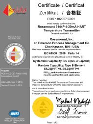
This report summarizes the results of the functional safety assessment according to <strong>IEC</strong> <strong>61508</strong><br />
carried out on the:<br />
‣ 3144P Temperature Transmitter<br />
The functional safety assessment performed by exida consisted of the following activities:<br />
- exida assessed the modifications performed by <strong>Emerson</strong> by an on-site audit and creation of<br />
a detailed safety case against the requirements of <strong>IEC</strong> <strong>61508</strong>.<br />
- exida performed a detailed Failure Modes, Effects, and Diagnostic Analysis (FMEDA) of the<br />
devices to document the hardware architecture and failure behavior. This included detailed<br />
Markov models of the fault tolerant architectures done in order to show accurate average<br />
probability of failure on demand.<br />
The functional safety assessment was performed to the requirements of <strong>IEC</strong> <strong>61508</strong>, SIL 2 for<br />
hardware and SIL 3 for the design process. This product was previously certified to <strong>IEC</strong> <strong>61508</strong>, SIL<br />
2 for hardware and SIL 3 for software by TUV (Certificate-Register-No.: SAS2550/04). Based on<br />
this assessment, it can be concluded that the <strong>Emerson</strong> development process meets the<br />
requirements of <strong>IEC</strong> <strong>61508</strong> for SIL 3. As a result this latest assessment focused on reviewing the<br />
changes made to the product. The changes were assessed against section 7.8 of <strong>IEC</strong> <strong>61508</strong> part<br />
2 (E/E/PES Modification) and section 7.8 of part 3 (Software Modification). A partial <strong>IEC</strong> <strong>61508</strong><br />
<strong>Safety</strong> Case was prepared, focusing specifically on the modification process, and used as the<br />
primary audit tool. Modification process requirements and all associated documentation were<br />
reviewed. Also the user documentation (safety manual) was reviewed.<br />
The results of the <strong>Functional</strong> <strong>Safety</strong> <strong>Assessment</strong> can be summarized by the following statements:<br />
The 3144P was found to meet the requirements of SIL 2 for random integrity @ HFT=0, SIL 3<br />
for random integrity @ HFT=1 and SIL 3 for systematic integrity.<br />
© exida Certification rosemount 11-02-57 r002 iec <strong>61508</strong> assessment.docx, 5/14/2012<br />
Michael Medoff Page 2 of 21
Table of Contents<br />
Management summary .................................................................................................... 2<br />
1 Purpose and Scope ................................................................................................... 5<br />
2 Project management .................................................................................................. 6<br />
2.1 exida Certification ....................................................................................................... 6<br />
2.2 Roles of the parties involved .......................................................................................... 6<br />
2.3 Standards / Literature used ............................................................................................ 6<br />
2.4 Reference documents .................................................................................................... 6<br />
2.4.1 Documentation provided by <strong>Emerson</strong> <strong>Process</strong> Management ............................. 6<br />
2.4.2 Documentation generated by exida ................................................................... 11<br />
3 Product Description .................................................................................................. 12<br />
3.1 3144P <strong>Safety</strong> Certified Temperature Transmitter ........................................................ 12<br />
4 <strong>IEC</strong> <strong>61508</strong> <strong>Functional</strong> <strong>Safety</strong> <strong>Assessment</strong> ............................................................... 13<br />
4.1 Methodology ................................................................................................................ 13<br />
4.2 <strong>Assessment</strong> level ......................................................................................................... 13<br />
5 Results of the <strong>IEC</strong> <strong>61508</strong> <strong>Functional</strong> <strong>Safety</strong> <strong>Assessment</strong> ........................................ 14<br />
5.1 Detailed Specification of the Modification or Change (Part 2, Section 7.8.2.1a) .......... 14<br />
5.2 Impact Analysis (Part 2, Section 7.8.2.1b) ................................................................... 14<br />
5.3 Approvals for changes (Part 2, Section 7.8.2.1c) ......................................................... 14<br />
5.4 Progress of Changes (Part 2, Section 7.8.2.1d) .......................................................... 14<br />
5.5 Test Cases Including Revalidation Data (Part 2, Section 7.8.2.1e) ............................. 14<br />
5.6 E/E/PES configuration management history (Part 2, Section 7.8.2.1f) ........................ 14<br />
5.7 Deviation from normal operations and conditions (Part 2, Section 7.8.2.1g) ............... 14<br />
5.8 Necessary changes to system procedures (Part 2, Section 7.8.2.1h) ......................... 15<br />
5.9 Necessary changes to documentation (Part 2, Section 7.8.2.1i) ................................. 15<br />
5.10 Modifications shall be performed with at least the same level of expertise, automated tools<br />
(see 7.4.4.2 of <strong>IEC</strong><strong>61508</strong>-3), and planning and management as the initial development of<br />
the E/E/PE safety-related systems (Part 2, Section 7.8.2.3) ........................................ 15<br />
5.11 Evidence that Change was reverified (Part 2, Section 7.8.2.4) .................................... 15<br />
5.12 For SIL 3, Entire System Must be validated (Table A.8) .............................................. 15<br />
5.13 A modification shall be initiated only on the issue of an authorized software modification<br />
request under the procedures specified during safety planning (Part 3, Section 7.8.2.1)15<br />
5.14 All modifications which have an impact on the functional safety of the E/E/PE safetyrelated<br />
system shall initiate a return to an appropriate phase of the software safety<br />
lifecycle. All subsequent phases shall then be carried out in accordance with the<br />
procedures specified for the specific phases in accordance with the requirements in this<br />
standard. <strong>Safety</strong> planning (see clause 6) should detail all subsequent activities (Part 3,<br />
Section 7.8.2.5) ............................................................................................................ 15<br />
© exida Certification rosemount 11-02-57 r002 iec <strong>61508</strong> assessment.docx, 5/14/2012<br />
Michael Medoff Page 3 of 21
5.15 The safety planning for the modification of safety-related software shall include<br />
identification of staff and specification of their required competency. (Part 3, 7.8.2.6a)15<br />
5.16 The safety planning for the modification of safety-related software shall include a detailed<br />
specification for the modification (Part 3, Section 7.8.2.6b) ......................................... 16<br />
5.17 The safety planning for the modification of safety-related software shall include verification<br />
planning (Part 3, Section 7.8.2.6c) ............................................................................... 16<br />
5.18 The safety planning for the modification of safety-related software shall include the scope<br />
of re-validation and testing of the modification to the extent required by the safety integrity<br />
level. For SIL 3 entire system must be revalidated. (Part 3, Section 7.8.2.6d) ........... 16<br />
5.19 Modification shall be carried out as planned (Part 3, Section 7.8.2.7) ......................... 16<br />
5.20 Details of all modifications shall be documented, including references to the<br />
modification/retrofit request (Part 3, Section 7.8.2.8a) ................................................. 16<br />
5.21 Details of all modifications shall be documented, including references to the results of the<br />
impact analysis which assesses the impact of the proposed software modification on the<br />
functional safety, and the decisions taken with associated justifications; (Part 3, Section<br />
7.8.2.8b) ....................................................................................................................... 16<br />
5.22 Details of all modifications shall be documented, including references to software<br />
configuration management history (Part 3, Section 7.8.2.8c) ...................................... 17<br />
5.23 Details of all modifications shall be documented, including references to deviation from<br />
normal operations and conditions (Part 3, Section 7.8.2.8d) ....................................... 17<br />
5.24 Details of all modifications shall be documented, including references to all documented<br />
information affected by the modification activity (Part 3, Section 7.8.2.8e) .................. 17<br />
5.25 Information (for example a log) on the details of all modifications shall be documented.<br />
The documentation shall include the re-verification and revalidation of data and results.<br />
(Part 3, Section 7.8.2.9) ............................................................................................... 17<br />
5.26 The assessment of the required modification or retrofit activity shall be dependent on the<br />
results of the impact analysis and the software safety integrity level. (Part 3, Section<br />
7.8.2.10) ....................................................................................................................... 17<br />
5.27 Hardware <strong>Assessment</strong> ................................................................................................. 18<br />
6 Terms and Definitions .............................................................................................. 20<br />
7 Status of the document ............................................................................................ 21<br />
7.1 Liability ......................................................................................................................... 21<br />
7.2 Releases ...................................................................................................................... 21<br />
7.3 Future Enhancements .................................................................................................. 21<br />
7.4 Release Signatures ...................................................................................................... 21<br />
© exida Certification rosemount 11-02-57 r002 iec <strong>61508</strong> assessment.docx, 5/14/2012<br />
Michael Medoff Page 4 of 21
1 Purpose and Scope<br />
Generally three options exist when doing an assessment of sensors, interfaces and/or final<br />
elements.<br />
Option 1: Hardware assessment according to <strong>IEC</strong> <strong>61508</strong><br />
Option 1 is a hardware assessment by exida according to the relevant functional safety standard(s)<br />
like <strong>IEC</strong> <strong>61508</strong> or EN 954-1. The hardware assessment consists of a FMEDA to determine the fault<br />
behavior and the failure rates of the device, which are then used to calculate the Safe Failure<br />
Fraction (SFF) and the average Probability of Failure on Demand (PFD AVG ).<br />
This option shall provide the safety instrumentation engineer with the required failure data as per<br />
<strong>IEC</strong> <strong>61508</strong> / <strong>IEC</strong> 61511 and does not include an assessment of the development process.<br />
Option 2: Hardware assessment with proven-in-use consideration according to <strong>IEC</strong> <strong>61508</strong> /<br />
<strong>IEC</strong> 61511<br />
Option 2 is an assessment by exida according to the relevant functional safety standard(s) like <strong>IEC</strong><br />
<strong>61508</strong> or EN 954-1. The hardware assessment consists of a FMEDA to determine the fault<br />
behavior and the failure rates of the device, which are then used to calculate the Safe Failure<br />
Fraction (SFF) and the average Probability of Failure on Demand (PFD AVG ). In addition, this option<br />
includes an assessment of the proven-in-use demonstration of the device and its software including<br />
the modification process.<br />
This option for pre-existing (programmable electronic) devices shall provide the safety<br />
instrumentation engineer with the required failure data as per <strong>IEC</strong> <strong>61508</strong> / <strong>IEC</strong> 61511 and justify the<br />
reduced fault tolerance requirements of <strong>IEC</strong> 61511 for sensors, final elements and other PE field<br />
devices.<br />
Option 3: Full assessment according to <strong>IEC</strong> <strong>61508</strong><br />
Option 3 is a full assessment by exida according to the relevant application standard(s) like <strong>IEC</strong><br />
61511 or EN 298 and the necessary functional safety standard(s) like <strong>IEC</strong> <strong>61508</strong> or EN 954-1. The<br />
full assessment extends option 1 by an assessment of all fault avoidance and fault control<br />
measures during hardware and software development.<br />
Option 4: <strong>Assessment</strong> of Modifications according to <strong>IEC</strong> <strong>61508</strong> for previously certified products<br />
Option 4 only applies to products that have already been certified to <strong>61508</strong> and have undergone<br />
changes. The changes are assessed specifically against the modification sections of <strong>IEC</strong> <strong>61508</strong><br />
(Section 7.8 of part 2 and 7.8 of part 3).<br />
This assessment shall be done according to option 4.<br />
This document shall describe the results of the <strong>IEC</strong> <strong>61508</strong> functional safety assessment of the<br />
3144P Temperature Transmitter.<br />
© exida Certification rosemount 11-02-57 r002 iec <strong>61508</strong> assessment.docx, 5/14/2012<br />
Michael Medoff Page 5 of 21
2 Project management<br />
2.1 exida Certification<br />
exida Certification is one of the world’s leading product certification and knowledge companies<br />
specializing in automation system safety and availability with over 300 years of cumulative<br />
experience in functional safety. Founded by several of the world’s top reliability and safety experts<br />
from assessment organizations and manufacturers, exida is a global company with offices around<br />
the world. exida offers training, coaching, project oriented services, safety lifecycle engineering<br />
tools, detailed product assurance and certification analysis and a collection of on-line safety and<br />
reliability resources. exida maintains a comprehensive failure rate and failure mode database on<br />
process equipment.<br />
2.2 Roles of the parties involved<br />
<strong>Emerson</strong> <strong>Process</strong> Management<br />
exida Certification<br />
Manufacturer of the 3144P Temperature Transmitter<br />
Performed the <strong>IEC</strong> <strong>61508</strong> <strong>Functional</strong> <strong>Safety</strong> <strong>Assessment</strong><br />
according to option 4 (see section 1)<br />
<strong>Emerson</strong> <strong>Process</strong> Management contracted exida in November 2011 with the <strong>IEC</strong> <strong>61508</strong> <strong>Functional</strong><br />
<strong>Safety</strong> <strong>Assessment</strong> of the above mentioned device.<br />
2.3 Standards / Literature used<br />
The services delivered by exida were performed based on the following standards / literature.<br />
[N1] <strong>IEC</strong> <strong>61508</strong> (Parts 1 - 7):<br />
2000<br />
<strong>Functional</strong> <strong>Safety</strong> of Electrical/Electronic/Programmable<br />
Electronic <strong>Safety</strong>-Related Systems<br />
2.4 Reference documents<br />
2.4.1 Documentation provided by <strong>Emerson</strong> <strong>Process</strong> Management<br />
Ref. Document ID Document Description Revision<br />
[D1] DOP 416 <strong>Safety</strong> Instrumented Systems<br />
Product Design and Development<br />
<strong>Process</strong><br />
Rev E<br />
[D2] DOP 440 Engineering Change Order Rev AE<br />
[D3] EDP 400-500 Peer Review Procedure Rev A.1<br />
[D4] EDP 400-300 Configuration and Change<br />
Management Procedure<br />
[D5] 701-063/2003T TUV Certification Report of the<br />
3144P SIS Temperature Transmitter<br />
Rev C<br />
Rev 1.0<br />
[D6] 03144-2108 AH to AJ.pdf Schematic marked up with changes 4/4/2006<br />
© exida Certification rosemount 11-02-57 r002 iec <strong>61508</strong> assessment.docx, 5/14/2012<br />
Michael Medoff Page 6 of 21
[D7] 3144P_<strong>Safety</strong>_ SIA1.xls <strong>Safety</strong> Impact Analysis for Hardware<br />
changes<br />
2/12/2007<br />
[D8] <strong>Safety</strong>Requirements.pdf <strong>Safety</strong> Requirements Specification Rev C.1<br />
[D9] SAS2550/04 TUV Certificate for 3144P SIS<br />
Temperature Transmitter<br />
10/27/2004<br />
[D10] 3144P_STD_SIS- HSTP.doc<br />
Hardware System Test Plan for the<br />
3144P HART Temperature<br />
Transmitter<br />
Rev. A<br />
[D11] 3144P_STD_SIS- STP.doc<br />
[D12] 3144P HART SCCT.htm<br />
[D13] 3144P STD/SIS SCCT.htm<br />
Software System Test Plan for the<br />
3144P HART Temperature<br />
Transmitter<br />
Minutes of Software Configuration<br />
Control Team meeting 5/23/06<br />
Minutes of Software Configuration<br />
Control Team meeting 11/30/06<br />
Rev. A.5<br />
12/14/06<br />
12/14/06<br />
[D14] 3144P_STD_SIS_ Accuracy.xls Test Results for Accuracy Test 12/14/06<br />
[D15] 3144P_std_sis_code_<br />
cons_log_and_report.xls<br />
Inspection Report for 3144P Code<br />
Changes (Discrepancies and Merge<br />
Standard with SIS)<br />
12/14/06<br />
[D16] 3144P_std_sis_pdp.xls 3144P Project Defined <strong>Process</strong> Rev. B<br />
[D17] 3144P_std_sis_sirs_<br />
cons_log_and_report.xls<br />
[D18] 3144P_std_sis_stp_<br />
cons_log_and_report.xls<br />
Inspection Report for <strong>Safety</strong><br />
Requirements Specification<br />
Inspection Report for Software<br />
System Test Plan<br />
Rev. C.0<br />
Rev. 0.1<br />
[D19] Accuracy-3144P_STD_ SIS.doc Test Report for Accuracy Test 12/14/06<br />
[D20] Approvals.pdf Approvals Listing for ECO<br />
#RTC1021941<br />
[D21] HTP-3144_AD589 replacement.doc<br />
12/14/06<br />
Hardware System Test Plan for the Rev. B<br />
3144 HART (headmount) transmitter<br />
[D22] Individual_log-HWtest_ Linda.xls Individual Inspection Log for<br />
Hardware System Test Plan<br />
[D23] Individual_log-HWtest_ Scott.xls Individual Inspection Log for<br />
Hardware System Test Plan<br />
Rev. A<br />
12/14/2006<br />
[D24] IntegrationTestSpec.pdf Integration Test Specification Rev. C.1<br />
[D25] It_dat.log Automated Integration Test Results 12/8/2006<br />
[D16] It_manual4_dat.log Manual Integration Test Results 12/8/2006<br />
© exida Certification rosemount 11-02-57 r002 iec <strong>61508</strong> assessment.docx, 5/14/2012<br />
Michael Medoff Page 7 of 21
[D17] Lint_SIS.out LINT Output 7/10/2006<br />
[D18] Lint_STD_SIS.out LINT Output 12/8/2006<br />
[D19] Schematic Review Notes.doc Design Review Minutes 11/18/05<br />
[D20] Summary_TraceMatrix.xls Requirements Traceability Matrix 2/12/07<br />
[D21] W__3144PH_source_<br />
embedded_it_results_<br />
3144p_std_sis_it_re.pdf<br />
Integration Test Report 12/14/2006<br />
[D21] User Manual Updates<br />
Scanned copy of marked up user<br />
manual. This copy lists changes that<br />
will be made to the user manual for<br />
this release<br />
12/20/06<br />
[D22] 00825-0100-4021 3144P Quick Installation Guide Rev. DA<br />
[D23] 00809-0100-4021 3144P Reference Manual Rev. EA<br />
[D24] 00813-0100-4021 3144P Product Data Sheet Rev. GA<br />
[D25] PRD00030658.DOC Impact Analysis for PRD #00030658 2/6/07<br />
[D26] PRD00030659.DOC Impact Analysis for PRD #00030659 2/5/07<br />
[D27] PRD00030666.DOC Impact Analysis for PRD #00030666 2/5/07<br />
[D28] PRD00030667.DOC Impact Analysis for PRD #00030667 2/5/07<br />
[D29] PRD00030671.DOC Impact Analysis for PRD #00030671 2/8/07<br />
[D30] PRD00030677.DOC Impact Analysis for PRD #00030677 2/6/07<br />
[D31] PRD00031035.DOC Impact Analysis for PRD #00031035 2/8/07<br />
[D32] PRD00031473.DOC Impact Analysis for PRD #00031473 2/8/07<br />
[D33] 3144p_std_sis_srs.html<br />
[D34] AO_4-20mA.doc<br />
[D35] Various<br />
[D36] AlarmCharacteristics_ 3144P_SIS.doc<br />
[D37] Various<br />
Software Requirements Specification<br />
for the 3144P HART®<br />
Standard/<strong>Safety</strong> Temperature<br />
Transmitter Project<br />
4-20 mA Ranging Test Results<br />
Summary<br />
4-20 mA Ranging Detailed Test<br />
Results Data<br />
Alarm Characteristic Test Results<br />
Summary<br />
Alarm Characteristic Test Results<br />
Data<br />
Rev B.2<br />
12/20/06<br />
12/13/06<br />
1/16/07<br />
12/13/06<br />
[D38] Continuity.doc Strip Chart Continuity Test Results 2/9/07<br />
© exida Certification rosemount 11-02-57 r002 iec <strong>61508</strong> assessment.docx, 5/14/2012<br />
Michael Medoff Page 8 of 21
[D39] Various<br />
[D40] Diagnostics-Pt1.doc<br />
Summary<br />
Strip Chart Continuity Test Results<br />
Data<br />
Diagnostics Part 1 Test Results<br />
Summary<br />
12/13/06 &<br />
2/6/07<br />
2/6/07<br />
[D41] Diagnostics-Pt1_SIS_STD.xls Diagnostics Part 1 Test Results Data 1/31/07<br />
[D42] LCD_Meter.doc LCD Meter Test Results 2/12/07<br />
[D43] Open_Sensor_Detection_<br />
3144P_STD_SIS.doc<br />
[D44] Various<br />
Open Sensor Detection Test Results<br />
Summary<br />
Open Sensor Detection Test Results<br />
Data<br />
1/16/07<br />
12/13/06<br />
[D45] Accuracy-3144P_STD_ SIS.doc Accuracy Test Results Summary 2/8/07<br />
[D46] 3144P_STD_SIS_ Accuracy.xls Accuracy Test Results Data 2/5/07<br />
[D47] TempEffect_3144P_STD_ SIS.doc<br />
[D48] 3144p_STD_<strong>Safety</strong>_ tempeffects.xls<br />
Temperature Effect Test Results<br />
Summary<br />
Temperature Effect Test Results<br />
Data<br />
2/9/07<br />
2/9/07<br />
[D49] NC604145 EMC Test Result Summary Rev. A<br />
[D50] 3144p_std_sis_it_report.html 3144P Integration Test Report 2/12/07<br />
[D51] Mohajer Training Records.xls Training Records/Competency<br />
Report<br />
[D52] 3144p_std_sis_<br />
LiteratureReview02092007.doc<br />
[D53] 3144p_std_sis_EmulatorTests.doc<br />
Meeting Minutes from User<br />
Documentation Review<br />
3144 <strong>Safety</strong> as Standard Emulator<br />
Test Results<br />
2/12/07<br />
2/12/07<br />
2/12/07<br />
[D54] RTC 1020023 Testing.pdf Test Results for ECO #RTC1020023 2/12/07<br />
[D55] Layout Review Notes Minutes from Layout Review<br />
Meeting<br />
[D56] Various<br />
[D57] 3144P_H7D_SIA_PRD00112145.doc<br />
[D58] 3144P_H7D_SIA_PRD00112195.doc<br />
[D59] 3144P_H7D_SIA_PRD00112196.doc<br />
Markup for user manual updates<br />
from user documentation review<br />
Completed Impact Analysis Form for<br />
change to product<br />
Completed Impact Analysis Form for<br />
change to product<br />
Completed Impact Analysis Form for<br />
change to product<br />
2/9/07<br />
2/12/07<br />
1/18/2012<br />
1/19/2012<br />
1/19/2012<br />
© exida Certification rosemount 11-02-57 r002 iec <strong>61508</strong> assessment.docx, 5/14/2012<br />
Michael Medoff Page 9 of 21
[D60] DanHerzogEduExp.pdf Competency report for Dan Herzog 4/13/2012<br />
[D61] Manual_cons_log_and_report.xls User Manual Inspection report 12/12/2012<br />
[D62] SW_Professional_Development<br />
Analysis_adammat.pdf<br />
[D63] SW_Professional_Development<br />
Analysis_JeffRoberts.pdf<br />
[D64] SW_Professional_Development<br />
Analysis_VivekS.pdf<br />
[D65] SW_Professional_Development<br />
Analysis_YuryK.pdf<br />
Competency Report for Adam<br />
Mateen<br />
3/29/2012<br />
Competency Report for Jeff Roberts 4/2/2012<br />
Competency Report for Vivek<br />
Shinde<br />
Competency Report for Yury<br />
Kuznetsov<br />
[D66] 3144P_H7D_SIA_PRD00XXXXXX.doc Completed Impact Analysis Forms<br />
for changes to product documented<br />
by PRD00XXXXXX where XXXXXX<br />
= 057645, 057821, 057869, 057888,<br />
057905, 057910, 112026, 112053,<br />
112081, 112127, 112145, 112164,<br />
112195, 112196, 112203, 112278,<br />
112293, 112297, 112298, 112301,<br />
112339, 112358, 112449, 112468,<br />
and 112478<br />
[D67] 3144P_H7D_SIA_Software.xls<br />
[D68] <strong>Safety</strong>Chcklist.pdf<br />
[D69] 3144P_H7D_Software_Fault_Injection<br />
Testing.doc<br />
[D70] 3144P_HART7_DraftManual_<br />
20120419.pdf<br />
Impact analysis for planned software<br />
changes.<br />
Completed signed safety manual<br />
review checklist<br />
3/30/2012<br />
3/30/2012<br />
Various<br />
Rev 0.4<br />
4/12/2012<br />
Software fault injection test results 1/26/2012<br />
3144P Temperature Transmitter<br />
Reference Manual (includes safety<br />
manual)<br />
Rev. GA<br />
© exida Certification rosemount 11-02-57 r002 iec <strong>61508</strong> assessment.docx, 5/14/2012<br />
Michael Medoff Page 10 of 21
2.4.2 Documentation generated by exida<br />
[R1] Rosemount 3144 Change<br />
Audit.xls<br />
[R2] ROS 11-02-057 R001,<br />
V1 R1, 4/13/2012<br />
[R3] ROS 11-02-057 R002,<br />
V1R1, 4/27/2012<br />
Detailed safety case documenting results of assessment<br />
(internal document)<br />
3144P SIS Temperature Transmitter FMEDA Report<br />
<strong>IEC</strong> <strong>61508</strong> <strong>Functional</strong> <strong>Safety</strong> <strong>Assessment</strong>, 3144P (this<br />
report)<br />
© exida Certification rosemount 11-02-57 r002 iec <strong>61508</strong> assessment.docx, 5/14/2012<br />
Michael Medoff Page 11 of 21
3 Product Description<br />
3.1 3144P Temperature Transmitter<br />
This report documents the results of the <strong>Assessment</strong> performed for the 3144P Temperature<br />
Transmitter with option code QT or QS and Hardware version 20 and Software version 1.1.X<br />
(Device Label SW REV 1.1.X). The 3144P Temperature Transmitter is a 2 wire 4-20 mA smart<br />
device. For safety instrumented systems usage it is assumed that the 4-20 mA output is used as<br />
the primary safety variable. The transmitter can be equipped with or without display.<br />
The 3144P Temperature Transmitter is classified as a Type B device according to <strong>IEC</strong> <strong>61508</strong> (See<br />
section 7.4.3.1.3 of <strong>IEC</strong> <strong>61508</strong>-2), having hardware fault tolerance of 0. Combined with one or two<br />
temperature sensing elements, the 3144P becomes a temperature sensor assembly. The<br />
temperature sensing elements that can be connected to the 3144P transmitter are:<br />
2-, 3-, and 4-wire RTD<br />
Thermocouple<br />
Millivolt Input (-10 to 100mV)<br />
2-, 3-, and 4-wire ohm input (0 to 2000Ω)<br />
© exida Certification rosemount 11-02-57 r002 iec <strong>61508</strong> assessment.docx, 5/14/2012<br />
Michael Medoff Page 12 of 21
4 <strong>IEC</strong> <strong>61508</strong> <strong>Functional</strong> <strong>Safety</strong> <strong>Assessment</strong><br />
The <strong>IEC</strong> <strong>61508</strong> <strong>Functional</strong> <strong>Safety</strong> <strong>Assessment</strong> was performed based on the information received<br />
from <strong>Emerson</strong> and is documented here.<br />
4.1 Methodology<br />
The full functional safety assessment includes an assessment of all changes made in comparison<br />
to the modification requirements of <strong>IEC</strong> <strong>61508</strong> (Section 7.8 of part 2 and 7.8 of part 3). In addition a<br />
Hardware FMEDA was performed to determine the safe failure fraction (SFF) and the average<br />
probability of failure on demand (PFD AVG ).<br />
4.2 <strong>Assessment</strong> level<br />
The 3144P has been assessed per <strong>IEC</strong> <strong>61508</strong> to the following levels:<br />
<br />
<br />
SIL 2 capability for a single device<br />
SIL 3 capability for multiple devices<br />
The development procedures have been assessed as suitable for use in applications with a<br />
maximum <strong>Safety</strong> Integrity Level of 3 (SIL3) according to <strong>IEC</strong> <strong>61508</strong>.<br />
© exida Certification rosemount 11-02-57 r002 iec <strong>61508</strong> assessment.docx, 5/14/2012<br />
Michael Medoff Page 13 of 21
5 Results of the <strong>IEC</strong> <strong>61508</strong> <strong>Functional</strong> <strong>Safety</strong> <strong>Assessment</strong><br />
exida assessed the changes made by <strong>Emerson</strong> for this development against the modification<br />
procedures of <strong>IEC</strong> <strong>61508</strong> parts 2 and 3. The assessment was done on November 10, 2011 on-site<br />
at Chanhassen, MN. Additionally a detailed safety case was completed, see [R2]. The specific<br />
part of <strong>61508</strong> and section number are given in parenthesis for each item below.<br />
All changes were successfully reviewed against the following criteria from <strong>IEC</strong> <strong>61508</strong>:<br />
5.1 Detailed Specification of the Modification or Change (Part 2, Section 7.8.2.1a)<br />
A detailed specification of all modifications are included in the impact analysis document.<br />
5.2 Impact Analysis (Part 2, Section 7.8.2.1b)<br />
All changes include a detailed safety impact analysis. The impact analysis details which phases of<br />
the development process need to be repeated and what output is required from each phase. The<br />
impact analysis is documented in either the change control system or in an independent document.<br />
For software, the impact analysis includes a complete listing of all changed software modules.<br />
5.3 Approvals for changes (Part 2, Section 7.8.2.1c)<br />
Approvals for all changes are documented via the change history in the software change request<br />
system and via electronic approvals for Engineering Change Orders (ECO’s). Both of these can<br />
easily be reviewed on-line.<br />
5.4 Progress of Changes (Part 2, Section 7.8.2.1d)<br />
Progress of all changes is documented via the change history in the software change request<br />
system and via electronic approvals for Engineering Change Orders (ECO’s). Both of these can<br />
easily be reviewed on-line.<br />
5.5 Test Cases Including Revalidation Data (Part 2, Section 7.8.2.1e)<br />
Test cases are documented as part of the impact analysis for all changes<br />
5.6 E/E/PES configuration management history (Part 2, Section 7.8.2.1f)<br />
Configuration Management history is documented via the version control system for all changes. In<br />
addition, all documents include the configuration management history within the document.<br />
5.7 Deviation from normal operations and conditions (Part 2, Section 7.8.2.1g)<br />
Deviations from normal operations and conditions is discussed in the impact analysis or FMEDA for<br />
all changes<br />
© exida Certification rosemount 11-02-57 r002 iec <strong>61508</strong> assessment.docx, 5/14/2012<br />
Michael Medoff Page 14 of 21
5.8 Necessary changes to system procedures (Part 2, Section 7.8.2.1h)<br />
Any changes to system procedures are documented in the impact analysis.<br />
5.9 Necessary changes to documentation (Part 2, Section 7.8.2.1i)<br />
All necessary documentation changes are included in the impact analysis<br />
5.10 Modifications shall be performed with at least the same level of expertise,<br />
automated tools (see 7.4.4.2 of <strong>IEC</strong><strong>61508</strong>-3), and planning and management as the<br />
initial development of the E/E/PE safety-related systems (Part 2, Section 7.8.2.3)<br />
Management assures that changes are carried out by qualified engineers. Engineer’s qualifications<br />
are tracked via an on-line system. Identical tools to the original development were used. An<br />
impact analysis is the basis for planning of each change.<br />
5.11 Evidence that Change was reverified (Part 2, Section 7.8.2.4)<br />
All changes had appropriate verification steps carried out. Verification included inspection, testing,<br />
and static analysis. Action items from inspections were tracked to closure.<br />
5.12 For SIL 3, Entire System Must be validated (Table A.8)<br />
Entire system was validated, however there were a few standard validation tests that were deemed<br />
not necessary to run because they were not impacted by any of the changes.<br />
5.13 A modification shall be initiated only on the issue of an authorized software<br />
modification request under the procedures specified during safety planning (Part 3,<br />
Section 7.8.2.1)<br />
All software changes submitted to the change control system and are authorized by CCT (Change<br />
Control Team)<br />
5.14 All modifications which have an impact on the functional safety of the E/E/PE<br />
safety-related system shall initiate a return to an appropriate phase of the software<br />
safety lifecycle. All subsequent phases shall then be carried out in accordance with<br />
the procedures specified for the specific phases in accordance with the<br />
requirements in this standard. <strong>Safety</strong> planning (see clause 6) should detail all<br />
subsequent activities (Part 3, Section 7.8.2.5)<br />
The impact analysis documents which phases need to be repeated and the phases are carried out<br />
according to standard procedures.<br />
5.15 The safety planning for the modification of safety-related software shall include<br />
identification of staff and specification of their required competency. (Part 3,<br />
7.8.2.6a)<br />
© exida Certification rosemount 11-02-57 r002 iec <strong>61508</strong> assessment.docx, 5/14/2012<br />
Michael Medoff Page 15 of 21
Competency forms are on file for all engineers that worked on the project. Identification of staff is<br />
included in the PRD system and the ECN system.<br />
5.16 The safety planning for the modification of safety-related software shall include<br />
a detailed specification for the modification (Part 3, Section 7.8.2.6b)<br />
A detailed specification of the modification is included in the impact analysis.<br />
5.17 The safety planning for the modification of safety-related software shall include<br />
verification planning (Part 3, Section 7.8.2.6c)<br />
Verification planning is included in the impact analysis.<br />
5.18 The safety planning for the modification of safety-related software shall include<br />
the scope of re-validation and testing of the modification to the extent required by<br />
the safety integrity level. For SIL 3 entire system must be revalidated. (Part 3,<br />
Section 7.8.2.6d)<br />
The validation test plan documented exactly which tests would be run. The entire system was<br />
revalidated, however there were a few standard validation tests that were deemed not necessary to<br />
run because they were not impacted by any of the changes.<br />
5.19 Modification shall be carried out as planned (Part 3, Section 7.8.2.7)<br />
Documentation showed that all of the work was carried out as planned.<br />
5.20 Details of all modifications shall be documented, including references to the<br />
modification/retrofit request (Part 3, Section 7.8.2.8a)<br />
The impact analysis references the modification request via the PRD ID (Unique identifier for each<br />
software change request)<br />
5.21 Details of all modifications shall be documented, including references to the<br />
results of the impact analysis which assesses the impact of the proposed software<br />
modification on the functional safety, and the decisions taken with associated<br />
justifications; (Part 3, Section 7.8.2.8b)<br />
The impact analysis documentation contains this information.<br />
© exida Certification rosemount 11-02-57 r002 iec <strong>61508</strong> assessment.docx, 5/14/2012<br />
Michael Medoff Page 16 of 21
5.22 Details of all modifications shall be documented, including references to<br />
software configuration management history (Part 3, Section 7.8.2.8c)<br />
The software configuration management history is documented and stored in the version control<br />
system. By looking at this system on-line, I was able to confirm that the software configuration<br />
management history was updated to account for the changes made.<br />
5.23 Details of all modifications shall be documented, including references to<br />
deviation from normal operations and conditions (Part 3, Section 7.8.2.8d)<br />
This was documented in the impact analysis.<br />
5.24 Details of all modifications shall be documented, including references to all<br />
documented information affected by the modification activity (Part 3, Section<br />
7.8.2.8e)<br />
The impact analysis included a listing of all documents that would be updated based on this<br />
change.<br />
5.25 Information (for example a log) on the details of all modifications shall be<br />
documented. The documentation shall include the re-verification and revalidation of<br />
data and results. (Part 3, Section 7.8.2.9)<br />
Details of all modifications are included in the impact analysis. Documentation exists for reverification<br />
(test reports, inspection reports, and static analysis results) and re-validation (test<br />
report).<br />
5.26 The assessment of the required modification or retrofit activity shall be<br />
dependent on the results of the impact analysis and the software safety integrity<br />
level. (Part 3, Section 7.8.2.10)<br />
The assessment was based on the results of the impact analysis and Rosemount’s standard<br />
procedures which have been certified to SIL 3 previously.<br />
© exida Certification rosemount 11-02-57 r002 iec <strong>61508</strong> assessment.docx, 5/14/2012<br />
Michael Medoff Page 17 of 21
5.27 Hardware <strong>Assessment</strong><br />
To evaluate the hardware design of the 3144P Temperature Tansmitter, a Failure Modes, Effects,<br />
and Diagnostic Analysis was performed by exida. This is documented in [R2].<br />
A Failure Modes and Effects Analysis (FMEA) is a systematic way to identify and evaluate the<br />
effects of different component failure modes, to determine what could eliminate or reduce the<br />
chance of failure, and to document the system in consideration. An FMEDA (Failure Mode Effect<br />
and Diagnostic Analysis) is an FMEA extension. It combines standard FMEA techniques with<br />
extension to identify online diagnostics techniques and the failure modes relevant to safety<br />
instrumented system design.<br />
From the FMEDA failure rates are derived for each important failure category. Table 1 lists these<br />
failure rates as reported in the FMEDA report for the case where a single 4-wire RTD is used. The<br />
failure rates are valid for the useful life of the devices. Based on <strong>Emerson</strong> endurance test data and<br />
general field failure data a useful life period of approximately 50 years is expected for the 3144P.<br />
This is listed in the FMEDA reports. Note that if the device is using a thermocouple rather than an<br />
RTD or if more than one RTD’s are used, the failure rates will differ and the FMEDA should be<br />
consulted to determine the correct failure rates.<br />
Table 1 Failure rates according to <strong>IEC</strong> <strong>61508</strong> – 3144P Temperature Transmitter with single RTD<br />
Failure Categories SD SU DD DU SFF<br />
Low trip 265 FIT 112 FIT 20 FIT 40 FIT 90.8%<br />
High trip 20 FIT 112 FIT 265 FIT 40 FIT 90.8%<br />
An average Probability of Failure on Demand (PFD AVG ) calculation is performed for a single (1oo1)<br />
3144P Temperature Transmitter with single 4-wire RTD. The failure rate data used in this<br />
calculation is displayed in section 5.2.1 or [R2]Error! Reference source not found.. It is assumed<br />
that the transmitter output is send low upon detection of failure and the safety function has a low<br />
trip point.<br />
The resulting PFD AVG values for a variety of proof test intervals are displayed in Figure 1. As shown<br />
in the figure the PFD AVG value for a single 3144P Temperature Transmitter with single 4-wire RTD,<br />
with a proof test interval of 1 year equals 2.38E-04.<br />
© exida Certification rosemount 11-02-57 r002 iec <strong>61508</strong> assessment.docx, 5/14/2012<br />
Michael Medoff Page 18 of 21
5.00E-03<br />
PFD AVG vs. Proof Test Interval<br />
Device 1<br />
4.50E-03<br />
4.00E-03<br />
3.50E-03<br />
PFDAVG<br />
3.00E-03<br />
2.50E-03<br />
2.00E-03<br />
1.50E-03<br />
1.00E-03<br />
5.00E-04<br />
0.00E+00<br />
1 2 3 4 5 6 7 8 9 10<br />
Years<br />
Figure 1: PFD AVG 3144P Temperature Transmitter with single RTD<br />
For SIL 2 applications, the PFD AVG value for the safety function needs to be < 10 -2 . This means that<br />
for a SIL 2 application, the PFD AVG for a 1-year Proof Test Interval of the 3144P Temperature<br />
Transmitter with single 4-wire RTD is equal to 2.4% of the range. These results must be considered<br />
in combination with PFD AVG values of other devices of a <strong>Safety</strong> Instrumented Function (SIF) in<br />
order to determine suitability for a specific <strong>Safety</strong> Integrity Level (SIL).<br />
The analysis shows that design of the 3144P meets the hardware requirements of <strong>IEC</strong> <strong>61508</strong>,<br />
SIL 2 @HFT=0 and SIL 3 @ HFT=1.<br />
© exida Certification rosemount 11-02-57 r002 iec <strong>61508</strong> assessment.docx, 5/14/2012<br />
Michael Medoff Page 19 of 21
6 Terms and Definitions<br />
Fault tolerance<br />
FIT<br />
FMEDA<br />
HFT<br />
Low demand mode<br />
PFD AVG<br />
SFF<br />
SIF<br />
SIL<br />
SIS<br />
Type A (sub)system<br />
Type B (sub)system<br />
Ability of a functional unit to continue to perform a required function in the<br />
presence of faults or errors (<strong>IEC</strong> <strong>61508</strong>-4, 3.6.3)<br />
Failure In Time (1x10 -9 failures per hour)<br />
Failure Mode Effect and Diagnostic Analysis<br />
Hardware Fault Tolerance<br />
Mode, where the frequency of demands for operation made on a safetyrelated<br />
system is no greater than twice the proof test frequency.<br />
Average Probability of Failure on Demand<br />
Safe Failure Fraction summarizes the fraction of failures, which lead to a<br />
safe state and the fraction of failures which will be detected by diagnostic<br />
measures and lead to a defined safety action.<br />
<strong>Safety</strong> Instrumented Function<br />
<strong>Safety</strong> Integrity Level<br />
<strong>Safety</strong> Instrumented System – Implementation of one or more <strong>Safety</strong><br />
Instrumented Functions. A SIS is composed of any combination of<br />
sensor(s), logic solver(s), and final element(s).<br />
“Non-Complex” (sub)system (using discrete elements); for details see<br />
7.4.3.1.2 of <strong>IEC</strong> <strong>61508</strong>-2<br />
“Complex” (sub)system (using micro controllers or programmable logic); for<br />
details see 7.4.3.1.3 of <strong>IEC</strong> <strong>61508</strong>-2<br />
© exida Certification rosemount 11-02-57 r002 iec <strong>61508</strong> assessment.docx, 5/14/2012<br />
Michael Medoff Page 20 of 21
7 Status of the document<br />
7.1 Liability<br />
exida prepares reports based on methods advocated in International standards. Failure rates are<br />
obtained from a collection of industrial databases. exida accepts no liability whatsoever for the use<br />
of these numbers or for the correctness of the standards on which the general calculation methods<br />
are based.<br />
7.2 Releases<br />
Version: V1<br />
Revision: R1<br />
Version History: V0, R1: Draft, April 27, 2012<br />
V1, R1: Updated based on comments on FMEDA report, May 14, 2012<br />
Review: V1, R1:<br />
Release status: Draft<br />
7.3 Future Enhancements<br />
At request of client.<br />
7.4 Release Signatures<br />
Dr. William M. Goble, Principal Partner<br />
Michael Medoff, Senior <strong>Safety</strong> Engineer<br />
© exida Certification rosemount 11-02-57 r002 iec <strong>61508</strong> assessment.docx, 5/14/2012<br />
Michael Medoff Page 21 of 21


