T31_prospect.pdf (ENG) - Iskraemeco
T31_prospect.pdf (ENG) - Iskraemeco
T31_prospect.pdf (ENG) - Iskraemeco

Create successful ePaper yourself
Turn your PDF publications into a flip-book with our unique Google optimized e-Paper software.
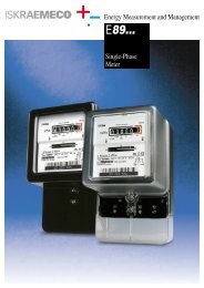
Energy Measurement and Management<br />
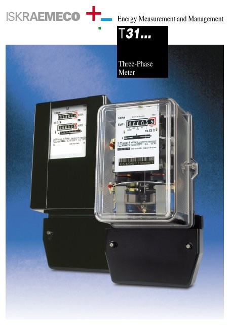
<strong>T31</strong>...<br />
Three-Phase<br />
Meter
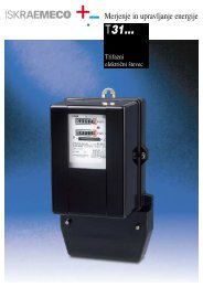
<strong>T31</strong>...<br />
The electricity meter type <strong>T31</strong>.. is suitable for measuring active energy for direct connection and connection via measuring transformers in<br />
three-phase three- or four-wire networks at balanced or unbalanced load.<br />
The measuring and technical characteristics of active meters comply with EN Publication 60 521, IEC Publication 521, and other national standards,<br />
such as VDE 0418, BS 5685...<br />
The accuracy class is 2. The meters connected via instrument transformers can be also class 1.<br />
Meter case<br />
The meter case is made of bakelite,<br />
highly resistant to creep current.<br />
Degree of protection complies with<br />
IEC 529 - IP 53.<br />
The meter cover is made of bakelite<br />
and is provided with a glass<br />
window through which a name<br />
plate, a register and a disc edge<br />
are visible. As option, it can be<br />
also made of transparent thermoplastic<br />
material. The cover is fastened<br />
to the base with two sealing<br />
screws, which enables sealing irrespective<br />
of the position of the terminal<br />
block cover.<br />
A suspension hook and a holding<br />
stirrup, which are intended for<br />
mounting the meter, are fastened<br />
to the base.<br />
Teminal block<br />
The terminal block is fastened to<br />
the base with a pin. Terminals are<br />
embedded in a bakelite framework.<br />
For main circuits, the terminal<br />
holes have a dia. 6.5 mm, which is<br />
enough for connection of outer<br />
wires of 25 mm 2 . Terminals for<br />
meters connected via instrument<br />
transformers have holes of 5.5 mm<br />
dia. The auxiliary terminals for connection<br />
of external circuits have the<br />
holes of 3.2 mm dia. The flashover<br />
and creep distances in the bakelite<br />
framework, between the metal parts<br />
of individual circuits on one hand,<br />
and terminals and outside contact<br />
parts on the other, are large<br />
enough to assure high breakdown<br />
strength.<br />
The terminal block cover is made<br />
of solid, self-extinguishable, thermoplastic<br />
material or thermoset. It<br />
can be supplied in short, extended<br />
or middle version.<br />
Measuring system<br />
The meter employs three similar<br />
electromagnet elements which are<br />
mounted on a robust die-cast<br />
frame. Two elements drive the lower<br />
disc and one the upper disc on<br />
which the brake magnet also operates.<br />
The two-disc rotor is made of aluminium<br />
sheet which is selected for<br />
its conductivity and purity. The<br />
2<br />
brake magnet is made of AlNiCo<br />
alloy, and sealed in a SiAl casting.<br />
The rotor upper bearing consists of<br />
a steel needle guide with a sintered<br />
graphite pivot. No lubrication is<br />
necessary. The lower bearing can<br />
be two-cup, ball or magnetic type.<br />
The voltage electromagnet of each<br />
element has a double magnetic circuit<br />
and the U-shape current electromagnet<br />
is used.<br />
Electromagnetic sheet of a corresponding<br />
initial permeability in current<br />
cores assures specified error<br />
curves with respect to the load,<br />
either at small loads or overloads.<br />
Register<br />
The register can be single-rate or<br />
two-rate type. It consists of six or<br />
seven graduated drums. The rear<br />
register circumference is divided in<br />
to 100 sections.<br />
A single-rate register can be provided<br />
with a standard digit drum<br />
with the size of numbers 4.7 x 2.3<br />
mm, and with a larger digit drum<br />
with the size of numbers 6.9 x 3.65<br />
mm. No lubrication of bearings is<br />
necessary.<br />
The two-rate register is available<br />
only in a standard digit drum version.<br />
The tariff switch-over is<br />
enabled by a change-over relay<br />
functioning via a differential gear.<br />
The change-over relay is a D.C.<br />
version and is supplied via the<br />
incorporated rectifier and the protective<br />
resistor.<br />
Reverse running stop<br />
A four-part stop is mounted beside<br />
the upper bearing and functions to<br />
the gear part of the upper bearing<br />
sleeve with a worm. The stop friction<br />
can be neglected. It does not<br />
influence in the meter accuracy and<br />
the start-up. If the impulse transmitter<br />
is built in the meter, a 24-<br />
part stop is mounted in the device.<br />
Impulse output<br />
Impulse transmitters (inductive type<br />
- 5 and opto-electronic type - 9 )<br />
are built into three-phase reactive<br />
electricity meters. The impulse<br />
transmitters can be supplied with<br />
SO (DIN 43 864) or a relay impulse<br />
output. The electromagnetic compatibility<br />
complies with IEC 1036,<br />
Articles 5.5.2. to 5.5.5.;<br />
Impulse frequency is proportional<br />
to meter rotor speed as well as to<br />
electric energy consumption.<br />
Transmission of pulses from the<br />
meter to the central unit is performed<br />
through special two-wire<br />
lines.<br />
3<br />
6<br />
5<br />
4<br />
8<br />
1<br />
7<br />
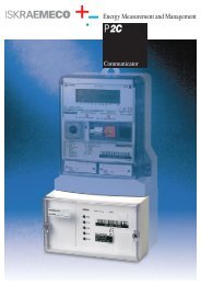
METER ADJUSTMENTS<br />
1 –sensitivity adjustment<br />
2 –coarse adjustment of number of revolutions<br />
3 –fine adjustment of number of revolutions<br />
4 –adjustment of small loads<br />
5 –coarse phase adjustment<br />
6 –fine phase adjustment<br />
7 –balance of torques of driving elements<br />
8 –reverse phase sequence adjustment
<strong>T31</strong>...<br />
TECHNICAL DATA<br />
METERS CONNECTED VIA<br />
DIRECTLY CONNECTED METERS<br />
INSTRUMENT TRANSFORMERS<br />
Type <strong>T31</strong>B.. <strong>T31</strong>C.. <strong>T31</strong>F.. <strong>T31</strong>L.. <strong>T31</strong>AT.. <strong>T31</strong>CT.. <strong>T31</strong>FT..<br />
Rated voltage (V) 3 x 230 / 400<br />
Rated frequency (Hz) 50 or 60<br />
Rated secondary current<br />
of current transformer (A) 5 5 5<br />
Basic current (A) 10 10 10 5 5 1.5 1<br />
Max. current (A) 30 40 60 40 6 6 6<br />
Thermal current (A) 36 48 72 48 7.2 7.2 7.2<br />
Self consumption<br />
in voltage circuits at (W) 3 x 1.10<br />
rated voltage (VA) 3 x 5.20<br />
Self consumption (at 5 A) (at 5 A)<br />
in current circuits at (W) 3 x 0.13 3 x 0.15 3 x 0.093 x 0.07 3 x 0.65 3 x 0.65 3 x 0.75<br />
basic current (VA) 3 x 0.15 3 x 0.16 3 x 0.11 3 x 0.08 3 x 0.81 3 x 0.81 3 x 1.07<br />
Torque at<br />
basic load (x10 -4 Nm) 8,8 8,6 6,6 7.0 10 8.8 6.8<br />
Rated number of<br />
revolutions at basic load (r.p.m.) 17.25 13.8 8.625 6.917.25 12.4 8.625<br />
Meter constant (r./kWh) 150 120 75 120 300 750 750<br />
Starting current at cos ϕ = 1<br />
< 0.5 % Ib<br />
No-load running<br />
Rotor does not run if the current circuit is open and if voltage varies from 80% to 110% Ur<br />
Weight of the rotor (g) approx. 52 with two-cup bearing, and 55 with magnetic bearing<br />
Weight of the meter (kg) approx. 3.4<br />
Sinusoidal test voltage<br />
2000 V rms<br />
Impulse voltage test<br />
> 7kV (1.2/50 µs)<br />
Other rated voltages up to 500 V and currents (5/20, 5/30, 2.5/10 A, 5(3-6)A ...) are also available on special request.<br />
METER TYPE DESIGNATION<br />
<strong>T31</strong>CTDP2-9<br />
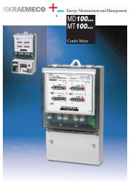
TYPICAL PERFORMANCE CHARACTERISTIC<br />
Load curves<br />
T – three-phase three-element meter<br />
31– meter case version<br />
A – 120 or 200-percent overload<br />
B – 300-percent overload<br />
C – 400-percent overload<br />
F – 600-percent overload<br />
L – 800-percent overload<br />
– (blank) direct connection<br />
T – connection via instrument transformers<br />
– (blank) single-tariff register<br />
D – double-tariff register<br />
– (blank) accuracy class 2<br />
P – accuracy class 1<br />
– (blank) two-cup, ball lower bearing<br />
2 – magnetic lower bearing<br />
5 – inductive impulse transmitter<br />
(SO output - DIN 43 864)<br />
8 – 24-part reverse running stop<br />
9 – opto-electronic impulse transmitter<br />
(SO - DIN 43 864 or relay output)<br />
+2<br />
+1<br />
F %<br />
–1<br />
–2<br />
+2<br />
+1<br />
F %<br />
–1<br />
–2<br />
+2<br />
+1<br />
F %<br />
–1<br />
–2<br />
<strong>T31</strong>AT (200% Ib)<br />
<strong>T31</strong>C, <strong>T31</strong>CT (400% Ib)<br />
<strong>T31</strong>F, <strong>T31</strong>FT (600% Ib)<br />
<strong>T31</strong>L (800% Ib)<br />
+2<br />
+1<br />
F %<br />
–1<br />
–2<br />
5 20 100 200 300 400 500 600 700 800 Ib %<br />
10<br />
Error due to temperature variation<br />
+2<br />
+1<br />
F %<br />
–1<br />
–2<br />
0 +10 +20 +30 +40<br />
+2<br />
+1<br />
F %<br />
–1<br />
–2<br />
–20 –10 0 +10 +20 +30 +40 +50 °C
6.1<br />
<strong>T31</strong>...<br />
CONNECTION DIAGRAMS<br />
4000<br />
4101<br />
4102<br />
Z<br />
Z<br />
10 12<br />
1 3 4 6 7 9<br />
L3<br />
N<br />
L1<br />
L2<br />
10 12<br />
1 2 3 4 6 7 9 11 13<br />
L3<br />
N<br />
L1<br />
L2<br />
1 2 3 4 6 7 9 1011<br />
1213 15<br />
L1<br />
L2<br />
L3<br />
N<br />
4010<br />
4020<br />
S0<br />
1 2 3 4 5 6 7 8 9 11<br />
1 2 3 4 5 6 7 8 9 11<br />
1 2 3 4 5 6 7 8 9 11<br />
20 21<br />
20 21<br />
k l<br />
k l<br />
k l<br />
u u u<br />
x x x<br />
k l<br />
k l<br />
k l<br />
u u u 4620<br />
x x x k l k l k l<br />
L1<br />
L2<br />
L3<br />
N<br />
K L<br />
K L<br />
K L<br />
L1<br />
L2<br />
L3<br />
X X X<br />
U U U<br />
K L<br />
K L<br />
K L<br />
L1<br />
L2<br />
L3<br />
X X X<br />
U U U<br />
K L<br />
K L<br />
K L<br />
OVERALL AND FIXING DIMENSIONS<br />
144<br />
6.25<br />
6.5<br />
1.5<br />
134<br />
Connection via measuring<br />
transformers<br />
13.5<br />
5.5<br />
15<br />
230<br />
9 x 9.45<br />
3 x 7.6<br />
204<br />
68<br />
23<br />
30<br />
6.5<br />
86<br />
140<br />
40<br />
150<br />
Direct connection<br />
13.5 14<br />
16<br />
16 13 16 13 16 13 9<br />
9.5<br />
8<br />
177<br />
42.5<br />
Owing to periodical improvements of our products the supplied products can differ in<br />
some details from the data stated in the <strong>prospect</strong>us material.<br />
722.999.125 9905/11<br />
<strong>Iskraemeco</strong>, Energy Measurement and Management<br />
4000 Kranj, Savska loka 4, Slovenia<br />
Telephone: (+386 64) 26 40, Telefax: (+386 64) 26 43 76, http://www.iskraemeco.si<br />
Published by <strong>Iskraemeco</strong>. Data subject to alteration without notice.