®Hydrovex® RDS Rotary Drum Sieve - Veolia Water Solutions ...
®Hydrovex® RDS Rotary Drum Sieve - Veolia Water Solutions ...
®Hydrovex® RDS Rotary Drum Sieve - Veolia Water Solutions ...

You also want an ePaper? Increase the reach of your titles
YUMPU automatically turns print PDFs into web optimized ePapers that Google loves.
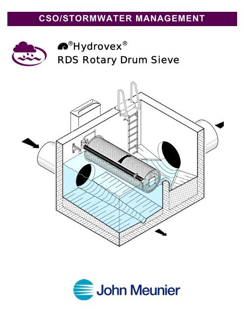
CSO/STORMWATER MANAGEMENT<br />
® Hydrovex ®<br />
<strong>RDS</strong> <strong>Rotary</strong> <strong>Drum</strong> <strong>Sieve</strong>
HYDROVEX ® <strong>RDS</strong> ROTARY DRUM SIEVE<br />
APPLICATION<br />
In spite of substantial successes in the treatment of stormwater in combined and storm drains, there are frequent complaints about<br />
the unsightly pollution of downstream shorelines by toilet paper, sanitary napkins, disposable syringes, diapers, kitchen wipes,<br />
plastic wrap, etc. These items often float in the effluent and cannot be effectively removed by sedimentation or trapped by baffles.<br />
To address this problem, static screens are sometimes used. Such screens block easily, as they cannot be cleaned under load and<br />
become useless. Trashracks with small bar spacing and forced mechanical cleaning can only be applied on very wide sewer<br />
overflows to reduce superficial loads.<br />
The HYDROVEX ® <strong>RDS</strong> <strong>Rotary</strong> <strong>Drum</strong> <strong>Sieve</strong> we have developed is especially designed to retain floatables in sewer overflows and<br />
sewer treatment facilities. We made a careful study of old effluent screening technology, which was common at the start of the<br />
century, before the development of biological wastewater treatment. We also tested sieves and cleaning systems of all kinds with<br />
real effluent.<br />
Figure 1: Stainless steel slotted drum, slot width W<br />
ADVANTAGES OF THE ROTARY DRUM SIEVE<br />
• Reliable retention of floatables and solids<br />
• Very large filtering surface in the smallest possible space by using a rotating cylindrical sieve<br />
• Large capacity with small footprint<br />
• Choice of three slot sizes<br />
• Extended widths available<br />
• Positive, above-water, mechanical cleaning by brushes<br />
• <strong>Sieve</strong>d material discharged into the waste effluent<br />
• Low energy requirements, no aerosols, no noise<br />
• Filtration effect and fine particle retention by controlled growth of filter matting<br />
• Robust stainless steel construction.
DESIGN AND OPERATION<br />
The core of the HYDROVEX ® <strong>RDS</strong> <strong>Rotary</strong> <strong>Drum</strong> <strong>Sieve</strong> is a large, smooth cylinder (1) (see Figure 1) made of welded stainless<br />
steel. The rotating filter is placed between two end plates (2). The cylinder is turned slowly by a hydraulic motor (3) on a gear<br />
wheel.<br />
A brush rotating arranged above the highest water level (4) and driven by a second motor (5) rotates in the opposite direction from<br />
the sieve. The brush bristles fit readily into the long slots of the sieve and provide reliable cleaning.<br />
During dry weather, the rotary sieve hangs in the air. With rising water levels, the drum is submerged and the effluent enters the<br />
sieve from the outside in. When water-level sensors, in the flushwater and the effluent, report excessive load on the sieve, the brush<br />
rollers and the sieve begin to turn. The sieved material is lifted out of the water and then returned to the water by the brushes. On<br />
the other side, the clean sieve surface is re-immersed in the water. The direction in which the roller turns is selected so that the<br />
clean side is facing the on-coming water.<br />
CONFIGURATIONS<br />
In free flow and storm settling tanks, the treatment conditions are generally favorable. In such case, the rotary sieve can be<br />
connected directly to the stainless steel trough of the sewer overflow. See the picture on the cover and Figure 2, Configuration A.<br />
The surface load in this configuration, with a small slot width of W = 2 mm, is quite low, only 57 to 93 L/s/m2, so that generally, a<br />
layer of matting is formed on the sieve and even very fine particles can be retained. The head loss in the sieve will vary with its size<br />
(see Table 1). The internal trough guarantees very even surface load. With larger flows, an overflow trough discharging on both<br />
sides may be necessary.<br />
With tank overflows, a large span must be covered. The whole interior diameter of the sieve is required for discharging the water<br />
and often it has to be discharged from both ends of the sieve. So that the overflow is not triggered prematurely, the overflow weir<br />
(6) is located either ahead of the sieve or behind it (see Configuration B and C, Figure 2). To provide sufficient large outlet<br />
capacity, HYDROVEX ® <strong>RDS</strong> <strong>Rotary</strong> <strong>Drum</strong> <strong>Sieve</strong>s of this type have a slot width of 3 mm and a surface load of 148 to 241 L/s/m2.<br />
To keep the height losses from the required overflow weirs as small as possible, we recommend attaching our HYDROVEX ® BW<br />
Bending Weir (7).<br />
Storm overflows of combined sewer systems must discharge very large volumes of water into the system without causing excessive<br />
backup. Transverse-flow sieves usually have slot diameters of 4 mm. The water flows through the sieve twice, but flows directly<br />
and over its full length, as in Configuration D. This type, which has the highest capacity, can nevertheless still retain fine materials<br />
due to its variable rotation speed. This type of sieve is very compact and fits in nicely with traditional storm overflow design.<br />
PERFORMANCE<br />
It is not economical to design filters for occasional peak flows, which may occur only a few minutes per year. In our experience, a<br />
design flow of 50% of Qd (n = 1) is effective. Occasional overflows are discharged through an emergency overflow, which is in<br />
any case included in any sieve system in sewer and tank overflows.<br />
The surface loads shown in Tables 1 to 3 refer each to 1 m 2 of submerged sieve area, assuming a ⅓ coating and maximum load.<br />
For each HYDROVEX ® <strong>RDS</strong> <strong>Rotary</strong> <strong>Drum</strong> <strong>Sieve</strong> installation, hydraulic measurement should be made of the head loss in the sieve,<br />
inlet and outlet ratios and the backpressure from the main outfall.
CONFIGURATION A<br />
HYDROVEX ® <strong>RDS</strong> <strong>Rotary</strong> <strong>Drum</strong> <strong>Sieve</strong> with<br />
axial flow, one two-sided and internal trough as<br />
substitute for effluent overflow in the flow tank<br />
or storm tank.<br />
CONFIGURATION B (emergency overflow)<br />
HYDROVEX ® <strong>RDS</strong> <strong>Rotary</strong> <strong>Drum</strong> <strong>Sieve</strong> with<br />
axial flow, one two-sided. Behind overflow of a<br />
storm overflow tank.<br />
CONFIGURATION C (emergency overflow)<br />
HYDROVEX ® <strong>RDS</strong> <strong>Rotary</strong> <strong>Drum</strong> <strong>Sieve</strong> with axial<br />
flow, one or two-sided. Ahead of overflow of a storm<br />
overflow tank.<br />
CONFIGURATION D<br />
Transverse flow HYDROVEX ® <strong>RDS</strong> <strong>Rotary</strong><br />
<strong>Drum</strong> <strong>Sieve</strong> ahead of a sewer overflow.<br />
Figure 2: Possible configurations of HYDROVEX ® <strong>RDS</strong> <strong>Rotary</strong> <strong>Drum</strong> <strong>Sieve</strong>s
TABLE 1:<br />
HYDROVEX ® <strong>RDS</strong> <strong>Rotary</strong> <strong>Drum</strong> <strong>Sieve</strong> with internal trough<br />
slot width w = 2 mm, Configuration A<br />
Diameter<br />
Surface<br />
load<br />
Maximum design capacity Qd in l/s<br />
<strong>Sieve</strong> length L<br />
D q 1 2 3 4 5 6<br />
m L/sm 2 m m m m m m<br />
0,75 57 89 178 267 - - -<br />
1,00 66 137 274 412 - - -<br />
1,25 73 192 383 575 787 - -<br />
1,50 80 252 504 786 1008 1260 -<br />
2,00 93 388 776 1164 1552 1940 2328<br />
TABLE 2:<br />
HYDROVEX ® <strong>RDS</strong> <strong>Rotary</strong> <strong>Drum</strong> <strong>Sieve</strong> with axial discharge<br />
in the sieve, slot width w = 3 mm, Configuration B and C<br />
Diameter<br />
Surface<br />
load<br />
Maximum sieve design capacity Qd in l/s<br />
<strong>Sieve</strong> length L<br />
D q 1 2 3 4 5 6<br />
m L/s/m 2 m m m m m m<br />
0,75 148 232 463 695 - - -<br />
1,00 170 357 713 1070 1426 - -<br />
1,25 190 498 997 1495 1993 2492 -<br />
1,50 209 655 1310 1965 2620 3278 3931<br />
2,00 241 1009 2017 3026 4034 5043 6062<br />
TABLE 3:<br />
Transverse Flow HYDROVEX ® <strong>RDS</strong> <strong>Rotary</strong> <strong>Drum</strong> <strong>Sieve</strong>,<br />
Aperture width W = 4 mm, Configuration D<br />
Diameter<br />
Surface<br />
Load<br />
Maximum sieve design capacity Qd in l/s<br />
<strong>Sieve</strong> length L<br />
D q 1 2 3 4 5 6<br />
m L/s/m 2 m m m m m m<br />
0,75 251 395 790 1185 - - -<br />
1,00 290 608 1216 1824 2432 - -<br />
1,25 325 850 1699 2549 3399 4248 -<br />
1,50 356 1117 2234 3351 4468 5585 -<br />
2,00 411 1720 3439 5159 6878 8598 -
SPECIFICATIONS<br />
HYDROVEX ® <strong>RDS</strong> <strong>Rotary</strong> <strong>Drum</strong> <strong>Sieve</strong>, D = 1500 mm, L = 4000 mm, W = 3 mm, Qd = 2620 L/s, two-sided axial discharge into<br />
the drum. Self-supporting welded construction with support rings and inset slot apertures, welded gear wheel, all stainless steel<br />
material, cleaning brushes with nylon bristles, with bearings on both sides. <strong>Sieve</strong> and brush driven by flameproof AC motors,<br />
power take-up 7 kW. Side plates with bearings for attaching to a vertical wall, stainless steel casing for motors and gears, SPS<br />
controls and water level probes in flush and tail water, operating, display and recording equipment.<br />
L<br />
One-sided discharge<br />
Two-sided discharge<br />
D<br />
0,75D<br />
Figure 3: HYDROVEX ® <strong>RDS</strong> <strong>Rotary</strong> <strong>Drum</strong> <strong>Sieve</strong> with internal<br />
water evacuation according to configuration A. D = 1.5 m,<br />
L = 5.5 m, Qb = 1800 e/s. The unit is currently in<br />
operation in Germany.<br />
Head Office<br />
4105 Sartelon<br />
St-Laurent (Quebec) Canada H4S 2B3<br />
Tel. : 514-334-7230 www.johnmeunier.com<br />
Fax : 514-334-5070 cso@johnmeunier.com<br />
Ontario Office<br />
2000 Argentia Road, Plaza 4, Unit 430<br />
Mississauga (Ontario) Canada L5N 1W1<br />
Tel. : 905-286-4846 www.johnmeunier.com<br />
Fax : 905-286-0488 ontario@johnmeunier.com<br />
Revised : 2006-02-23