STT 3000 Series STT250 - Merkantile
STT 3000 Series STT250 - Merkantile
STT 3000 Series STT250 - Merkantile
You also want an ePaper? Increase the reach of your titles
YUMPU automatically turns print PDFs into web optimized ePapers that Google loves.
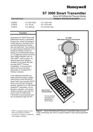
<strong>STT</strong> <strong>3000</strong> <strong>Series</strong> <strong>STT</strong>250<br />
SMART TEMPERATURE TRANSMITTER<br />
Models <strong>STT</strong>25H, <strong>STT</strong>25M, <strong>STT</strong>25D<br />
EN0I-6031 12/00<br />
PRODUCT SPECIFICATION SHEET<br />
OVERVIEW<br />
Honeywell’s <strong>STT</strong> <strong>3000</strong> family of<br />
microprocessor based smart<br />
temperature transmitters includes<br />
both the <strong>Series</strong> <strong>STT</strong>250 described<br />
in this specification sheet and the<br />
higher performance <strong>STT</strong>350<br />
described in Product Specification<br />
Sheet EN0I-5222. The <strong>STT</strong>350<br />
offers high performance and<br />
advanced functionality.<br />
The <strong>STT</strong>250 units offer competitive<br />
performance in a more compact<br />
module and with a wider range of<br />
smart communications protocols.<br />
Choose the unit to meet your<br />
application needs :<br />
• <strong>STT</strong>25H with HART protocol<br />
when this popular protocol is<br />
preferred. Configuration of the<br />
HART unit can be made with any<br />
of the listed HART Communication<br />
Foundation tools.<br />
• <strong>STT</strong>25M for 4-20mA operation and<br />
local/ remote configuration via<br />
Honeywell’s digital DE protocol<br />
from the Smart Field<br />
Communicator (SFC) or Smart<br />
Configuration Toolkit PC based<br />
software (SCT).<br />
• <strong>STT</strong>25D with digital DE protocol<br />
for either 4-20mA operation or<br />
digital integration into the TDC<br />
<strong>3000</strong>/ TPS <strong>3000</strong> control<br />
system.<br />
Note that the latest addition to the<br />
<strong>STT</strong>250 family is the Dual Input<br />
<strong>STT</strong>25T. The two sensor inputs may<br />
be used for sensor cross checking or<br />
for sensor redundancy.<br />
This is described in separate Product<br />
Specification Sheet EN0I-6091.<br />
All units support the same wide range<br />
of primary sensor types, are 2 wire<br />
powered and give an output linearised<br />
to temperature over the 2 power<br />
wires. Leadwire compensation is<br />
provided for RTD (Resistance<br />
Temperature Detectors) and internal<br />
digital cold junction compensation is<br />
provided for Thermocouples. MilliVolt<br />
and Ohms sensor inputs can also be<br />
accepted.<br />
FEATURES<br />
• Smart communication protocols<br />
available include HART or DE<br />
Honeywell.<br />
• Direct sensor head mounting in<br />
DIN Form A housing. Housing<br />
materials available include plastic,<br />
aluminium, 316SS and cast iron.<br />
• Mounting options include wall, pipe,<br />
DIN rail or direct sensor head<br />
mounting with or without a housing.<br />
• Single model accepts input signal<br />
from a wide choice of primary<br />
sensors to satisfy varying<br />
application requirements with<br />
minimum transmitter inventory.<br />
• Suitable for 4, 3 or 2 wire Pt100<br />
and Pt200 RTD measurement.<br />
• Hard wired upscale/ downscale<br />
failsafe link to ensure secure<br />
operation in the event of a failure.<br />
• Open circuit sensor analysis<br />
carried out in every measurement<br />
cycle.<br />
• Selectable latching/non-latching<br />
failsafe operation for open circuit<br />
sensor.<br />
• Integral analogue or digital<br />
indication meter option.<br />
• Analogue to Digital converter<br />
validated frequently.<br />
DESCRIPTION<br />
The <strong>STT</strong>250 transmitters are suitable<br />
as replacements for any conventional<br />
or most smart temperature<br />
transmitters in use today. The memory<br />
contains the characteristics of most<br />
commonly used temperature sensors.<br />
HART is a registered trademark of the HART Communication Foundation<br />
You can easily use the hand held<br />
communicator or PC tool to configure<br />
the transmitter for any of these<br />
sensors and it will automatically<br />
correct for their associated nonlinearity’s.<br />
Accuracies stated below are available<br />
merely by selecting the sensor type<br />
and range (i.e. without user<br />
calibration).<br />
Calibration of the LRV/URV end<br />
points will typically give accuracy<br />
improvements of 2 times. Sensor<br />
errors can be calibrated out by<br />
calibration to the specific sensor<br />
either by having it at the LRV/URV<br />
temperatures or by simulation of the<br />
known values.<br />
In addition, all units pass through<br />
Environmental Stress Screening by<br />
fast cycling between -40°C and +85°C<br />
to ensure maximum product reliability.<br />
During this process the ambient<br />
temperature coefficients are<br />
determined for each unit and burned<br />
into memory to ensure temperature<br />
compensation over a wide range of<br />
operating conditions.<br />
Configuration adjustments and<br />
diagnostics checks can be made<br />
either locally or remotely over the<br />
signal wires from anywhere along<br />
their route. This enables major<br />
savings in manpower time during<br />
commissioning, start up and<br />
maintenance activities.
Performance Under Rated Conditions<br />
Sensor<br />
Digital Accuracy over Normal<br />
Range<br />
°C (°F)<br />
D/A<br />
Accuracy<br />
% of<br />
span<br />
Digital Accuracy over<br />
Maximum Range<br />
°C (°F)<br />
Standards<br />
Pt100 0.15C for -200 to 450 (-328 to 842) 0.025% 0.25C for -200 to 850C (-328 to 1562) IEC751(ITS-90)(α=0.00385)<br />
Pt200 0.30C for -200 to 450 (-328 to 842) 0.025% 0.40C for -200 to 850C (-328 to 1562) IEC751(ITS-90)(α=0.00385)<br />
Pt100J 0.15C for -200 to 450 (-328 to 842) 0.025% 0.25C for -200 to 640C (-328 to 1184) JISC1604-81(α=0.00392)<br />
Ω 0.40Ω for 0 to 1000Ω 0.025% 0.40Ω for 0 to 2,000Ω *<br />
mV 15µV for -20 to 120mV 0.025% 15µV for -20 to 120mV<br />
B 1.0C for 550 to 1820 (1022 to 3308) 0.025% 3.0C for 200 to 1,820C (392 to 3308) IEC 584-1(ITS-90)<br />
E 0.30C for 0 to 1000 (32 to 1832) 0.025% 0.60C for -200 to 1,000C (-328 to 1832) IEC 584-1(ITS-90)<br />
J 0.30C for 0 to 800 (32 to 1472) 0.025% 0.70C for -200 to 1,200C (-328 to 2192) IEC 584-1(ITS-90)<br />
K 0.60C for -120 to 1370 (-191 to 2498) 0.025% 0.90C for -200 to 1370C (-328 to 2498) IEC 584-1(ITS-90)<br />
N 0.40C for 0 to 1300 (32 to 2372) 0.025% 1.5C for -200 to 1300C (-328 to 2372) IEC 584-1(ITS-90)<br />
R 0.60C for 500 to 1760 (932 to 3200) 0.025% 1.0C for -50 to 1760C (-58 to 3200) IEC 584-1(ITS-90)<br />
S 0.60C for 500 to 1760 (932 to 3200) 0.025% 1.0C for -50 to 1760C (-58 to 3200) IEC 584-1(ITS-90)<br />
T 0.30C for -100 to 400 (-148 to 752) 0.025% 0.5C for -250 to 400C ( -418 to 752) IEC 584-1(ITS-90)<br />
* 4 wire ohms input only<br />
SPECIFICATIONS<br />
Operating Conditions<br />
Parameter Reference Condition Rated Condition Operative Limits Transportation And<br />
Storage<br />
Ambient temperature °C 23 °C ± 2 -40 to +85 -40 to +85 -50 to +100<br />
Humidity<br />
Rack mounted % RH 10 to 55 5 to 95 5 to 100 5 to 100<br />
In field housing % RH 10 to 55 5 to 100 5 to 100 5 to 100<br />
Supply voltage<br />
Voltage range 10.8 to 35 Vdc at the transmitter terminals<br />
Output current<br />
Current overrange 3.8 to 20.8 mA. Failsafe limits < 3.8 and 21.8 mA<br />
Load resistance 0 to 1110Ω<br />
Vibration<br />
Maximum of 4g over 15 to 200Hz (restricted to 3g with indication meter).<br />
Shock Maximum of 40g.<br />
Performance Specifications<br />
Output D/A accuracy: ±0.025% of span<br />
Cold Junction accuracy: ±0.5°C<br />
Total reference accuracy: Analogue 4-<br />
20mA mode = Digital accuracy + Output<br />
D/A accuracy + CJ accuracy (T/Cs only)<br />
Total reference accuracy: Digital DE mode<br />
= Digital accuracy + CJ accuracy (T/Cs<br />
only).<br />
(example: transmitter operating in<br />
analogue mode with Pt100 sensor and 0 to<br />
200°C range.<br />
Total reference accuracy =<br />
0.15+(200/100)*0.025 = 0.2°C.<br />
Digital ambient temperature effect (per<br />
10°C change from 23°C ref.): RTDs or<br />
Ohms : 0.050% of reading in Ohms.<br />
: T/Cs or mV : 0.080% of reading in mV.<br />
Output D/A ambient temp. effect (per 10°C<br />
change from 23°C ref.): ±0.045% of span.<br />
Cold Junction ambient temperature effect:<br />
40: 1 rejection for ambient temperature<br />
changes from 23°C reference.<br />
Total output ambient temperature effect :<br />
Analogue 4-20mA mode = Digital effect +<br />
Output D/A effect + CJ effect (T/Cs only).<br />
Total output ambient temperature effect:<br />
Digital DE mA mode = Digital effect + CJ<br />
effect (T/Cs only).<br />
Power supply voltage effect: 0.005% of<br />
Max span per Volt.<br />
Stability/time drift: 0.05% of max span per<br />
year.<br />
Additional Parameters<br />
Output: 4-20mA or Honeywell digital DE<br />
protocol. HART and DE available with 4-<br />
20mA output.<br />
Adjustment range: No limits to<br />
adjustments within the Maximum Range<br />
except minimum span limit of 1<br />
engineering unit e.g. 1°C<br />
Damping time constant: Adjustable from 0<br />
to 102 seconds digital damping.<br />
Output response time:<br />
1 second to reach 63% of final value with 0<br />
secs damping.<br />
Output update time<br />
0.5 secs approximately.<br />
Input/ output galvanic isolation Withstands<br />
500Vac dielectric strength test for 1<br />
minute.<br />
Sensor open circuit<br />
Open circuit/ burnout detection is user<br />
selectable. Upscale or downscale with<br />
critical status message. Latching or nonlatching<br />
sensor burnout action.<br />
Common mode rejection<br />
120dB (1 million to 1) from 50Hz to 50<br />
kHz.<br />
<strong>Series</strong> mode rejection<br />
40dB (100 to 1) for 50 or 60Hz ±0.5Hz.<br />
(with internal software filter set to local<br />
power line frequency).<br />
EMC compliance<br />
In compliance with 89/336/EEC,<br />
ElectroMagnetic Compatibility (EMC)<br />
Directive.<br />
RFI rejection: ±0.1% of span at 30V/m<br />
over 20 to 1,000MHz in metallic housing<br />
and with shielded cables.<br />
2<br />
EN0I-6031
Physical Mounting, Construction and Integral Meters<br />
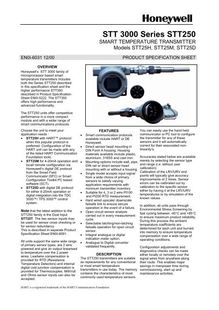
The <strong>STT</strong>250 Temperature Transmitter is designed to be mounted in a DIN Form A housing for direct<br />
installation with the temperature sensor or can be provided in a remote pipe or wall mount housing.<br />
Details on the various housings and integral meters available are given in specification sheet EN0I-<br />
6032. The <strong>STT</strong>250 Temperature Transmitter module can also be DIN rail mounted to a top hat or “G”<br />
rail via a clip.<br />
<strong>STT</strong>250 Module Dimensions (in mm)<br />
52<br />
29.2<br />
50<br />
33<br />
<strong>STT</strong>250 Connections<br />
White<br />
White<br />
RTD<br />
Red<br />
2 wires RTD<br />
or 2 wires ohm<br />
White<br />
RTD<br />
Red<br />
Red<br />
3 wires RTD<br />
or 3 wires ohm<br />
White<br />
Red<br />
Red<br />
4 wires RTD<br />
or 4 wires ohm<br />
RTD<br />
+<br />
-<br />
Single T/C<br />
+<br />
-<br />
Materials of Construction<br />
Terminal Block<br />
Noryl<br />
Connection Screws M3 Nickel plated brass<br />
Module Housing Cycoloy (PC/ABS) with metallised interior surface<br />
Weight<br />
0.075 kg (0.2 lbs)<br />
Approvals<br />
The <strong>STT</strong>250 Temperature Transmitter module is Intrinsically Safe to Cenelec, FM and CSA standards when used<br />
with a suitable safety barrier. It is zone 2 and explosion-proof to Cenelec, FM and CSA standards when installed<br />
in a suitable housing. See the Model Selection Guide Table VII in this Specification Sheet for detailed safety<br />
approvals covering both the <strong>STT</strong>250 module only or for the <strong>STT</strong>250 module supplied in a housing.<br />
Probe and Thermowell Availability<br />
<strong>STT</strong>250 can be supplied complete with any of the previously listed thermocouple or RTD sensors and with any of<br />
a wide range of thermowells. The sensors are of Mineral Insulated (MI) construction with lengths of up to 2 meters<br />
available. For the direct head mount installation the sensor is supplied with a mounting plate for <strong>STT</strong>250 module<br />
attachment and fixing screws to provide the spring loaded attachment to the housing. For EEx d IIC T6<br />
applications a flame trap is included between the sensor and sensor entry of the housing. See details on the<br />
standard sensors available in EN0I-6033 for Europe, or 34-44-29-01 for North America.<br />
The range of thermowells available as a total thermal solution cover almost every possible requirement :<br />
Materials:<br />
Carbon Steel, 304SS, 316SS, 316L SS, Hastelloy C-276, Monel 400, Inconel, and many others<br />
Thermowell Types: Threaded or flanged, with or without lagging and solid drilled, forged or fabricated construction<br />
Flange Types: Raised Face, Flat Face and Ring Type joint flanges available in 1 to 3 inch sizes or 15 to<br />
200mm<br />
Flange Ratings: ANSI 150 to 2500, BS 4504 NP6 to NP100, BS 10 Tables D to K and API 6A 5000 to 15000lb<br />
Other materials, types and accessories are available on request.<br />
EN0I-6031 3
Model Selection Guide<br />
INSTRUCTIONS<br />
1. Select key number and Table selections as required. A dot denotes unrestricted<br />
availability. A letter denotes restricted availability. See restrictions overleaf.<br />
2. Make selections from each table to fully define the required model as in the example.<br />
3. If more than one Table VI selection is required, separate them with a comma e.g. 03,XX.<br />
Example: <strong>STT</strong>25H - 0 - E N M - T C E - 0 1 0 - 0 D C - 0 0 - 3 S<br />
Key No. Tab. I Tab. II Tab. III Tab. IV Tab. V Tab. VI Tab. VII<br />
HOW WILL THE UNIT BE MOUNTED<br />
Availability<br />
Module only (no housing), to be DIN rail or wall mounted<br />
Module to be "head mounted" directly to the sensor in smaller housing<br />
Module to be "field mounted" in Explosion-proof housing remotely from or directly to the sensor<br />
KEY NUMBER<br />
SELECTION<br />
Smart Temperature Transmitter Module<br />
4 - 20mA output, SFC/SCT configurable <strong>STT</strong>25M • • •<br />
4 - 20mA output, HART protocol <strong>STT</strong>25H • • •<br />
4 - 20mA/DE output, for digital integration <strong>STT</strong>25D • • •<br />
4 - 20mA output, dual input, HART protocol <strong>STT</strong>25T • • •<br />
All modules carry the following approvals:<br />
CE Mark for compliance to EN 50081-2 and 50082-2<br />
Russian Certificate of Pattern Approval No 2064 of Jan.1998<br />
Choose safety approvals required in Table VII<br />
TableI - Sensor, Probe and Thermowell Accessories<br />
No Integral Sensor, Probe or Thermowell Supplied 0 • • •<br />
Sensor Probe and/ or thermowell mounted or tested with <strong>STT</strong> <strong>3000</strong> (1) 1 • h<br />
TABLE II Transmitter Housing and Integral Meters (Reference EN0I-6032 for details)<br />
No housing supplied 0 - - •<br />
Explosion-proof Aluminium with baked on beige E - - •<br />
Housing Field Polyester/ Epoxy hybrid paint<br />
Mount Explosion-proof Aluminium with beige Epoxy paint X - - •<br />
Explosionproof 316 Stainless Steel T - - •<br />
Head Aluminium direct head mount - beige Epoxy paint A - - •<br />
Mount EEx d flameproof cast iron direct head mount housing B - - •<br />
Cable/ Not applicable - No housing supplied - 0 - •<br />
Conduit Cable/Conduit entry M20 x 1.5 - Process/Sensor entry 1/2"NPT - M - •<br />
Entry Cable/Conduit entry 1/2"NPT - Process/Sensor entry 1/2"NPT - N - • •<br />
Integral No meter supplied - - 0 • • •<br />
Display Integral analogue meter - - M •<br />
Meter (2) Integral smart meter - - S •<br />
Note : (1) Use Sensor/ Well Model Selection Guide (Pages <strong>STT</strong>-25MSG-7 to 11).<br />
(2)<br />
Remote mounting meters available as Model RMA <strong>3000</strong><br />
Table III Configuration, Tagging & Manual<br />
SELECTION<br />
Configuration None - factory default supplied 0 - - • • •<br />
Transmitter configuration T - - • • •<br />
Customer tagging (3) No tagging required - 0 - • • •<br />
Customer ID tag on module, housing and certificates - C - • • •<br />
Customer ID tag on 316SS wired-on tag and certif. - T - • •<br />
316SS blank wired on tag - B - • •<br />
-C- & -T- - 3 - • •<br />
-C- & -B- - 4 - • •<br />
Operators Manual None - - 0 • • •<br />
English language version - - E i i i<br />
French language version - - F i i i<br />
Spanish language version - - S i, n i, n i, n<br />
Chinese language version - - C i, n i, n i, n<br />
4<br />
EN0I-6031
Table IV Optional Equipment<br />
No mounting arrangement 0 - - • • •<br />
Mounting Carbon steel pipe mounting bracket for 2" pipe M - - •<br />
Arrangement Stainless Steel mounting bracket for 2" pipe S - - •<br />
Spring loading mounting set L - - • •<br />
DIN rail mounting clip (top hat or G rail) D - - •<br />
M20 adaptors (4) No adaptors required - 0 - • • •<br />
1/2"NPT to M20x1.5 (EEx d IIC approved) 1 adaptor - 1 - f<br />
2 adaptors - 2 - f<br />
3/4"NPT adaptors (4) 1/2"NPT to 3/4"NPT 1 adaptor - 3 - f<br />
2 adaptors - 4 - f<br />
Lightning Protection No lightning protection supplied - - 0 • • •<br />
External lightning protection - - L e, j<br />
Internal surge / lightning protection - - S •<br />
Table V Optional Extended Warranty Coverage and Certification<br />
Standard warranty 0 - - • • •<br />
Optional Additional warranty - 1 year 1 - - • • •<br />
Extended Additional warranty - 2 years 2 - - • • •<br />
Warranty Additional warranty - 3 years 3 - - • • •<br />
Additional warranty - 4 years 4 - - • • •<br />
Additional warranty - 5 years 5 - - • • •<br />
No transmitter configuration/ calibration certificate - 0 - • • •<br />
Optional Transmitter configuration/ calibration certificate - D - • • •<br />
Certificates No certificate of conformance or statement of origin - - 0 • • •<br />
Certificate of conformance and statement of origin - - C • • •<br />
Table VI Additional Features<br />
No selection 0 0 • • •<br />
Use <strong>STT</strong> <strong>3000</strong> Special / Additional Features MSG for appropriate code X X • • •<br />
Note : (3) Full model number does not appear on module or direct head mount housing.<br />
If model number is to appear, order wired on tag.<br />
(4)<br />
Cenelec EEx d IIC approved adaptor provided only when option 3D Table VII selected<br />
Table VII Safety Approvals<br />
No approvals 0 0 • • •<br />
CENELEC Intrinsic Safety EEx ia IIC T6/T5/T4 3 S • • •<br />
CENELEC Flame Proof EEx d IIC T6 3 D • d<br />
Non-Sparking certification for Zone 2 T6, 30V/22mA 3 N • •<br />
Explosion-Proof Class I, Div. 1, Groups A,B,C,D<br />
Dust Ignition-Proof Class II, III Div. 1, Groups E,F,G<br />
Intrinsically Safe Class I, II, III, Div. 1, Groups A-G 1C e,<br />
Non-Incendive Class I, Div. 2, Groups A,B,C,D m<br />
Suitable for Class II, III, Div. 2,<br />
Groups F, G<br />
Outdoor Location NEMA 4X<br />
Explosion-Proof Class I, Div. 1, Groups B,C,D<br />
Dust Ignition-Proof Class II, III, Div. 1 Groups E,F,G<br />
Intrinsically Safe Class I, II, III, Div. 1, Groups A-G 1J m<br />
Non-Incendive Class I, Div. 2, Groups A,B,C,D<br />
Suitable for Class II, III, Div. 2,<br />
Groups F, G<br />
Factory Outdoor Location NEMA 4X<br />
Mutual Intrinsically Safe Class I, II, III, Div. 1,<br />
Groups A,B,C,D,E,F,G 1G m<br />
Non-Incendive Class I, Div. 2, Groups A,B,C,D<br />
Suitable for Class II, III, Div. 2,<br />
Groups F, G<br />
Outdoor Location NEMA 4X<br />
Intrinsically Safe Class I, Div. 1, Groups A,B,C,D<br />
Non-Incendive Class I, Div. 2, Groups A,B,C,D 1G m<br />
Table VII Safety Approvals (continued)<br />
Explosion-Proof Class I, Div. 1, Groups B,C,D<br />
Dust Ignition-Proof Class II, III, Div. 1, Groups E,F,G<br />
EN0I-6031 5
Suitable for Class I, II, III, Div. 2,<br />
Groups A,B,C,D,E,F,G 2J m<br />
CSA Intrinsically Safe Class I, II, III, Div. 1, Groups A-G.<br />
Outdoor Location Enclosure Type 4X<br />
Intrinsically Safe Class I, II, III, Div. 1, Groups A-G. 2S m<br />
Suitable for Class I, II, III, Div. 2,<br />
Groups A,B,C,D,E,F,G<br />
Outdoor Location Enclosure Type 4X<br />
Intrinsically Safe Class I, Div. 1, Groups A,B,C,D 2S m<br />
Suitable for Class I, Div.2.,Groups A,B,C,D<br />
Restrictions:<br />
d Available only with Table I selection 1 and Table II selection B - -.<br />
e Available only with Table II selections EN0, TN0 or XN0.<br />
f Not available with Table IV selection - - L, or with Table VII selections 1C, 1J, or 2J<br />
h Not available with Table VII selections 2J, 1J, 1C i.e. CSA & FM explosionproof approvals<br />
i For 1 to 9 transmitters, 1 to 9 manuals supplied; for 10 to 19 transmitters, 10 manuals; for 20 to 29 transmitters, 11 manuals….<br />
j Not available with Table VII selection 3D.<br />
m Safety approvals pending for <strong>STT</strong>25T<br />
n Not available for <strong>STT</strong>25T<br />
Distributor :<br />
Honeywell<br />
Industrial Automation and Control<br />
Helping You Control Your World<br />
Honeywell Inc.<br />
In the U.S.A.: Honeywell Industrial Automation and Control, 16404 North Black Canyon Hwy., Phoenix, AZ 85023, (602) 313-5000<br />
In Europe: Honeywell PACE, 1 Avenue du Bourget, B-1140 Brussels, Belgium, (32) 2-728-211<br />
Honeywell S.A., Zone Industrielle de Longpré, F-80084 Amiens Cédex 2, France, (33-3) 22-54-56-56<br />
In Asia: Honeywell Asia Pacific Inc., Honeywell Building, 17 Changi Business Park, Central 1, Singapore 486073. (65) 355 2828<br />
In the Mediterranean: Africa & Middle East Region, Honeywell SpA, Via Vittor Pisani 13, 20124 Milano, Italy, (39-2) 67731<br />
In Canada: The Honeywell Centre, 155 Gordon Baker Rd., North York, Ontario M2H 3N7, 1-800-461-0013<br />
In Latin America: Honeywell Inc., 14505 Commerce Way, Suite 500, Miami Lakes, Florida 33016-1556, (305) 3642300<br />
6<br />
EN0I-6031


