The Irregular Z-Buffer and its Application to Shadow Mapping
The Irregular Z-Buffer and its Application to Shadow Mapping
The Irregular Z-Buffer and its Application to Shadow Mapping

You also want an ePaper? Increase the reach of your titles
YUMPU automatically turns print PDFs into web optimized ePapers that Google loves.
¢<br />
<strong>The</strong> <strong>Irregular</strong> Z-<strong>Buffer</strong> <strong>and</strong> <strong>its</strong> <strong>Application</strong> <strong>to</strong> <strong>Shadow</strong> <strong>Mapping</strong><br />
Gregory S. Johnson 1 2 ¡ William R. Mark 1 † Chris<strong>to</strong>pher A. Burns 1 2 ‡<br />
Department of Computer Sciences 1 Texas Advanced Computing Center 2<br />
<strong>The</strong> University of Texas at Austin<br />
Abstract<br />
<strong>The</strong> classical Z-buffer algorithm samples a scene at regularly<br />
spaced points on an image plane. We present an extension of<br />
this algorithm called the irregular Z-buffer that perm<strong>its</strong> sampling<br />
of the scene at arbitrary points on the image plane. <strong>The</strong> sample<br />
points are s<strong>to</strong>red in a two-dimensional spatial data structure which<br />
is queried during rasterization. <strong>The</strong> irregular Z-buffer can be applied<br />
<strong>to</strong> shadow rendering, where we demonstrate that it eliminates<br />
the sampling artifacts previously associated with shadow mapping.<br />
We describe the extensions <strong>to</strong> modern graphics hardware necessary<br />
<strong>to</strong> support efficient operation of the irregular Z-buffer, <strong>and</strong> simulate<br />
the performance on the extended hardware. Our results indicate<br />
that the irregular Z-buffer can be used <strong>to</strong> produce hard shadows<br />
that are as accurate as those produced by a ray tracer or shadow<br />
volume-based renderer. We also find that shadow mapping on the<br />
irregular Z-buffer retains many of the performance <strong>and</strong> applicationdevelopment<br />
simplicity advantages of st<strong>and</strong>ard shadow mapping.<br />
CR Categories: I.3.1 [Computer Graphics]: Hardware<br />
Architecture—Graphics Processors; I.3.7 [Computer Graphics]:<br />
Three-Dimensional Graphics <strong>and</strong> Realism—Visible Line / Surface<br />
Algorithms; I.3.7 [Computer Graphics]: Three-Dimensional<br />
Graphics <strong>and</strong> Realism—<strong>Shadow</strong>s;<br />
Keywords: visible surface algorithms, shadow algorithms, realtime<br />
graphics hardware<br />
1 Introduction<br />
One of the fundamental computational tasks in three-dimensional<br />
graphics is the visible surface problem: <strong>to</strong> efficiently find the first<br />
intersection point between a ray <strong>and</strong> a collection of surfaces. In<br />
rendering, the visible surface problem is typically solved for many<br />
rays <strong>and</strong> a single collection of surfaces. Examples include visibility<br />
determination from an eye point, shadow computation, <strong>and</strong> computation<br />
of global illumination solutions.<br />
Today, the visible surface problem is typically solved by either<br />
the Z-buffer algorithm [Catmull 1974] or by ray casting using a spatial<br />
acceleration structure [Whitted 1980]. <strong>The</strong> Z-buffer algorithm<br />
is appropriate for many rays that share a common origin <strong>and</strong> share<br />
a known pattern of directions. It does not require any preprocessing<br />
of the surfaces. In contrast, the ray casting algorithm solves the visible<br />
surface problem for the general case – one or more rays with<br />
arbitrary origins <strong>and</strong> directions – but requires preprocessing of the<br />
surfaces <strong>to</strong> build a spatial acceleration structure.<br />
We present an algorithm that is more general than the classical<br />
Z-buffer, but does not require preprocessing of surfaces. This approach,<br />
which we refer <strong>to</strong> as the irregular Z-buffer, efficiently solves<br />
the visibility problem for rays that share a common origin but have<br />
arbitrary directions (Figure 2).<br />
Our algorithm represents ray directions as points on an image<br />
plane, as in the classical Z-buffer approach. However, we explic-<br />
e-mail: johnsong@cs.utexas.edu<br />
† e-mail: billmark@cs.utexas.edu<br />
‡ e-mail: cslugg@cs.utexas.edu<br />
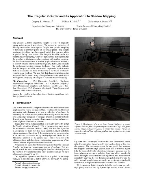
Figure 1: Two images of a scene from Doom 3 (alpha). A screen<br />
capture directly from the game engine is shown at <strong>to</strong>p. <strong>The</strong> game<br />
engine employs shadow volumes <strong>to</strong> render this image. <strong>The</strong> lower<br />
image is rendered by a software pipeline that implements irregular<br />
shadow maps.<br />
itly s<strong>to</strong>re all of the sample locations in a two-dimensional spatial<br />
data structure rather than implicitly representing them with a regular<br />
pattern. <strong>The</strong> data structure can be any spatial data structure<br />
that supports efficient range queries, such as a k-d tree or a grid.<br />
Like the classical Z-buffer algorithm, we project triangles on<strong>to</strong> the<br />
image plane one at a time <strong>and</strong> then determine which samples lie<br />
inside a triangle. Unlike the classical algorithm, this determination<br />
is made by querying the two-dimensional spatial data structure. Finally,<br />
for each sample inside a triangle, we perform the st<strong>and</strong>ard Z<br />
comparison <strong>and</strong> update at the sample’s address in a Z-buffer.<br />
We demonstrate that the irregular Z-buffer can be used <strong>to</strong> render<br />
high quality shadows cast by a point light source, as seen from a
Figure 2: A taxonomy of solutions <strong>to</strong> the visible surface problem,<br />
classified by the extent <strong>to</strong> which eye rays share origins <strong>and</strong> directions.<br />
known eye point. We propose changes <strong>to</strong> current graphics architectures<br />
that permit our algorithm <strong>to</strong> execute efficiently. Finally,<br />
we simulate the performance of shadow rendering using the irregular<br />
Z-buffer. Our results indicate that the approach is suitable for<br />
real-time use on our proposed architecture.<br />
Figure 3: <strong>The</strong> classical Z-buffer (left) samples a scene at regularly<br />
spaced points on an image plane. <strong>The</strong> irregular Z-buffer (right)<br />
samples a scene at arbitrary points on an image plane.<br />
can vary asymp<strong>to</strong>tically depending on the choice of data structure,<br />
the overall distribution of sample points, <strong>and</strong> the order in which the<br />
points are inserted. Once the data structure has been built, the cost<br />
of range queries depends on these same fac<strong>to</strong>rs as well. However,<br />
even algorithms with the same asymp<strong>to</strong>tic cost have different effective<br />
costs that vary with usage patterns <strong>and</strong> the underlying hardware<br />
architecture. Finally, the s<strong>to</strong>rage requirements of the data structures<br />
vary <strong>and</strong> only certain ones can guarantee a fixed memory footprint<br />
regardless of point distribution.<br />
For the shadow-mapping application on which we focus, the<br />
point distribution is somewhat even across large regions of the image<br />
plane, so we found that a hybrid data structure composed of<br />
a grid at the <strong>to</strong>p level <strong>and</strong> a secondary data structure below it performs<br />
better than a simple k-d tree. We gathered statistics on two<br />
variants of the two-level structure: a grid of lists <strong>and</strong> a grid of k-d<br />
trees, both implemented with guaranteed s<strong>to</strong>rage bounds. We determined<br />
that the grid of lists (including optimizations described<br />
later) performed best for our data sets. <strong>The</strong> reasons for this result<br />
are that our average list size is small <strong>and</strong> that the point-in-area test<br />
at each step of list traversal is simpler than the area-<strong>to</strong>-area overlap<br />
test required at each step of k-d tree traversal. <strong>The</strong> difference<br />
was not overwhelming, <strong>and</strong> the outcome could be different for less<br />
balanced point distributions or a different architecture.<br />
Constructing the grid-of-lists data structure is straightforward:<br />
we first determine which grid cell a point maps <strong>to</strong>, then prepend<br />
that point <strong>to</strong> the linked list for that cell. <strong>Irregular</strong> rasterization using<br />
this data structure is also simple. First, we determine which<br />
grid cell(s) the triangle overlaps. This test is just like conventional<br />
rasterization with the minor difference that we must consider any<br />
overlap between the triangle <strong>and</strong> a cell as a hit, rather than just an<br />
overlap between the triangle <strong>and</strong> the cell’s center. At each cell that<br />
the triangle overlaps, we traverse the linked list <strong>to</strong> test all of the<br />
cell’s points against each of the triangle’s three edges. A point that<br />
passes all three edge tests is inside the triangle.<br />
3 <strong>Shadow</strong> Rendering<br />
2 <strong>The</strong> <strong>Irregular</strong> Z-<strong>Buffer</strong><br />
<strong>The</strong> Z-buffer algorithm processes scene geometry one polygon at a<br />
time. Each polygon is projected on<strong>to</strong> the image plane. An edgewalking<br />
or edge equation computation is used <strong>to</strong> determine which<br />
sample points (i.e. pixels) lie inside the projected polygon.<br />
Answering this range query is simple when the positions of the<br />
sample points are implicitly defined by a simple formula, such as<br />
that for a regular grid (Figure 3, left side). Classical rasterization<br />
algorithms target this case <strong>and</strong> evaluate the formula directly – they<br />
do not explicitly s<strong>to</strong>re the location of each sample point.<br />
However, if the locations of the sample points cannot be represented<br />
by a simple formula (Figure 3, right side), the st<strong>and</strong>ard<br />
rasterization approach does not work. In this paper we propose<br />
an alternative approach <strong>to</strong> h<strong>and</strong>le this case. We explicitly s<strong>to</strong>re the<br />
points in a spatial data structure. During rasterization, a range query<br />
is performed on this data structure <strong>to</strong> determine which points are inside<br />
a triangle. We refer <strong>to</strong> this task as irregular rasterization.<br />
<strong>The</strong> data structures <strong>and</strong> algorithms needed for efficient range<br />
queries are well unders<strong>to</strong>od [Samet 1990]. Range queries can be<br />
performed efficiently for points s<strong>to</strong>red in two-dimensional space<br />
partitioning data structures such as BSP trees <strong>and</strong> quadtrees or their<br />
specialized variants such as k-d trees. If the points are somewhat<br />
evenly distributed, then grids are also efficient for this task.<br />
<strong>The</strong> best choice of data structure depends on several fac<strong>to</strong>rs. If<br />
the set of sample points changes often – as it does for the shadow<br />
mapping problem we examine later in this paper – then the cost of<br />
constructing the data structure is important. <strong>The</strong> construction cost<br />
<strong>Shadow</strong>s provide important spatial cues <strong>and</strong> add <strong>to</strong> the realism of<br />
computer generated images. <strong>Shadow</strong> rendering algorithms are often<br />
placed in<strong>to</strong> two categories: those for point light sources (hard<br />
shadows) <strong>and</strong> those for area light sources (soft shadows) [Assarsson<br />
<strong>and</strong> Akenine-Möller 2003; Chan <strong>and</strong> Dur<strong>and</strong> 2003]. In this paper<br />
we focus on hard shadow algorithms. In particular, we consider the<br />
problem of rendering shadows in real-time for scenes containing<br />
moving <strong>and</strong> deforming objects. Even though this problem is conceptually<br />
simple <strong>and</strong> is of practical interest, existing approaches <strong>to</strong><br />
it have significant shortcomings with respect <strong>to</strong> image quality or<br />
their performance on complex scenes.<br />
Object-space methods such as shadow volumes [Crow 1977;<br />
Everitt <strong>and</strong> Kilgard 2002] can achieve artifact-free hard shadows if<br />
implemented carefully. As a result, mainstream application developers<br />
such as id Software have chosen <strong>to</strong> use the approach in stateof-the-art<br />
video games like the upcoming Doom 3. <strong>The</strong> shadow<br />
volume technique creates <strong>and</strong> rasterizes extra polygons that demarcate<br />
the boundaries between volumes of space in <strong>and</strong> out of shadow<br />
in the scene. <strong>The</strong>se extra polygons connect object silhouette edges<br />
(as seen from the light source) <strong>to</strong> infinity. <strong>The</strong> polygons are rasterized<br />
from the eye view in<strong>to</strong> a stencil buffer, where a counter is incremented<br />
or decremented at each pixel <strong>to</strong> track the shadowed/nonshadowed<br />
status of the pixel. <strong>The</strong> polygons are often large, so the<br />
technique requires hardware with a very high fill rate. Even with<br />
recent hardware <strong>and</strong> software optimizations [NVIDIA Corp. 2003;<br />
McGuire et al. 2003], use of the technique requires that geometric<br />
scene complexity be held well below what would otherwise be<br />
possible.
£<br />
Raytracing [Whitted 1980] <strong>and</strong> related techniques can accurately<br />
render a variety of global illumination effects including hard shadows.<br />
It is possible that real-time rendering systems will eventually<br />
adopt raytracing techniques. However, even with recent progress in<br />
this area [Wald et al. 2003], rendering performance remains inadequate<br />
for scenes containing deformable objects.<br />
<strong>Shadow</strong> mapping [Williams 1978] <strong>and</strong> many of <strong>its</strong> variants<br />
[Hourcade <strong>and</strong> Nicolas 1985; Fern<strong>and</strong>o et al. 2001] leverage existing<br />
Z-buffer hardware <strong>to</strong> render shadows with high performance<br />
for complex scenes. However, existing versions of the technique are<br />
prone <strong>to</strong> sampling <strong>and</strong> self-shadowing artifacts that are sufficiently<br />
serious <strong>to</strong> limit the technique’s use in real applications.<br />
Figure 4 (left) illustrates the shadow map algorithm. <strong>The</strong> scene<br />
is rendered first from the light position (yielding Z near values) <strong>and</strong><br />
then rendered from the eye position. Each pixel in the eye view is<br />
treated as a 3-space point positioned according <strong>to</strong> <strong>its</strong> X / Y position<br />
in the image plane <strong>and</strong> <strong>its</strong> Z value (from the depth buffer), <strong>and</strong><br />
is transformed in<strong>to</strong> light space. This transformation yields a point<br />
P in light space <strong>and</strong> a distance Z P between P <strong>and</strong> the light-view<br />
image plane. <strong>The</strong> original eye-space pixel is considered <strong>to</strong> be in<br />
¤<br />
shadow iff Z near Z P , using an estimated Z near value. <strong>The</strong> algorithm<br />
estimates Z near from the Z near values of one or more lightview<br />
sample(s) that are nearest <strong>to</strong> the projection of point P on<strong>to</strong> the<br />
light-view image plane. This estimation step is the primary cause<br />
of artifacts produced by the technique as the estimation error is generally<br />
unbounded.<br />
Most recent efforts <strong>to</strong> reduce these artifacts have taken one of two<br />
approaches. <strong>The</strong> first is <strong>to</strong> use additional information from objectspace<br />
silhouette computations <strong>to</strong> reduce or eliminate estimation errors<br />
for the most common cases [Sen et al. 2003]. This approach<br />
seems <strong>to</strong> be the most successful at reducing the incidence of estimation<br />
artifacts, but sharp corners <strong>and</strong> details are often truncated or<br />
lost due <strong>to</strong> limited precision in the con<strong>to</strong>urs used <strong>to</strong> represent the<br />
silhouettes. Also, the need for object-space computation introduces<br />
additional complexity in<strong>to</strong> the rendering system. <strong>The</strong> second approach<br />
is <strong>to</strong> adapt the sampling rate in the light-view image plane <strong>to</strong><br />
the characteristics of the scene [Fern<strong>and</strong>o et al. 2001; Stamminger<br />
<strong>and</strong> Drettakis 2002], thereby reducing the average distance between<br />
a projection of P <strong>and</strong> the nearest sample point. Fern<strong>and</strong>o et al. [Fern<strong>and</strong>o<br />
et al. 2001] replace the st<strong>and</strong>ard light view image with an<br />
adaptive image hierarchy. This focus on improving shadow quality<br />
through strategic placement of shadow map sample points is similar<br />
<strong>to</strong> our own, but we take this approach <strong>to</strong> <strong>its</strong> logical extreme by<br />
placing sample points in their ideal locations.<br />
4 <strong>Irregular</strong> <strong>Shadow</strong> <strong>Mapping</strong><br />
Pseudocode for irregular shadow mapping is shown in Figure 5.<br />
<strong>The</strong> scene is first rendered from the eye point. As in conventional<br />
shadow mapping, pixels (at the Z values given by the Z-buffer) are<br />
transformed in<strong>to</strong> light space, yielding P <strong>and</strong> Z P . Unlike conventional<br />
shadow mapping, scene geometry is then rasterized <strong>to</strong> sample<br />
positions in the light view image plane given by the projection<br />
of the transformed pixels, yielding Z near . As before, a pixel<br />
¤<br />
is in shadow iff Z near Z P . Note that irregular shadow maps are<br />
view-dependent. Samples are computed in the shadow map plane<br />
precisely where required by pixels in the eye view. <strong>The</strong>refore, no<br />
mismatch exists between the sampling rates or sample positions in<br />
eye <strong>and</strong> light space. Aliasing <strong>and</strong> self-shadowing are avoided, <strong>and</strong><br />
no unnecessary samples are computed. Moreover, given points P<br />
prior <strong>to</strong> rasterization in light space, <strong>and</strong> the property that Z near is<br />
always less than or equal <strong>to</strong> Z P , we can maximize our use of the<br />
available Z-buffer precision.<br />
Figure 6 plots the location of sample points within irregular<br />
shadow maps for the Doom 3 scene from Figure 1. <strong>The</strong> density of<br />
sample points varies significantly across the image plane, demon-<br />
Figure 4: Conventional (left) <strong>and</strong> irregular (right) shadow mapping.<br />
In the case of the former, the scene is rendered <strong>to</strong> a conventional<br />
Z-buffer from the light, <strong>and</strong> then from the eye. With the latter,<br />
the scene is rendered <strong>to</strong> a conventional Z-buffer from the eye, <strong>and</strong><br />
<strong>to</strong> an irregular Z-buffer from the light.<br />
strating the importance of adaptive <strong>and</strong> irregular sampling methods<br />
in this context.<br />
Observe that irregular shadow mapping effectively mimics<br />
shadow generation by ray tracing. Points P match the intersection<br />
points between eye rays <strong>and</strong> scene geometry; <strong>and</strong> steps 2, 4 <strong>and</strong> 6<br />
imitate light ray computation. Unlike ray tracing, irregular shadow<br />
mapping is an object-order algorithm, which means that primitives<br />
are processed in the order submitted by the application. In this<br />
way, our approach combines the image quality <strong>and</strong> sampling characteristics<br />
of ray-traced shadows with the system organization <strong>and</strong><br />
performance characteristics of Z-buffer rendering.<br />
4.1 Image Quality<br />
We compare the quality of images produced by irregular shadow<br />
mapping <strong>to</strong> that of several other approaches. Figure 1 shows that<br />
images generated using irregular shadow mapping are visually indistinguishable<br />
from those produced by the shadow volumes technique.<br />
Figure 7 shows that irregular shadow mapping eliminates<br />
shadow aliasing artifacts commonly associated with conventional<br />
shadow mapping. In Figure 8 we use an L2 norm <strong>to</strong> compare<br />
quantitatively the image quality of our approach <strong>to</strong> that of three<br />
other approaches. Our quantitative comparison is made against<br />
ray-traced shadows <strong>and</strong> against two other shadow mapping algorithms<br />
that avoid object-space computations: conventional shadow<br />
mapping [Williams 1978] <strong>and</strong> adaptive shadow mapping [Fern<strong>and</strong>o<br />
et al. 2001]. This figure illustrates that the number of shadow map<br />
samples required <strong>to</strong> attain high fidelity is much less than that required<br />
by these other shadow mapping techniques.<br />
Our conventional <strong>and</strong> adaptive implementations include st<strong>and</strong>ard<br />
enhancements <strong>to</strong> reduce self-shadowing <strong>and</strong> shadow aliasing<br />
artifacts. <strong>The</strong>se enhancements include percentage closer filtering<br />
(PCF) [Reeves et al. 1987], object IDs [Hourcade <strong>and</strong> Nicolas<br />
1985] <strong>and</strong> orientation-dependent bias values like those computed by<br />
glPolygonOffset [OpenGL Architectural Review Board 2003].
Figure 5: A comparison of conventional <strong>and</strong> irregular shadow<br />
mapping. Steps labeled with “*” are repeated per light source.<br />
PCF <strong>and</strong> glPolygonOffset rely on configurable parameters. We<br />
carefully h<strong>and</strong> tune these parameters for each image of each test<br />
scene <strong>to</strong> minimize the difference in L2 norms from the baseline<br />
ray-traced image. Additionally, the field of view used for rendering<br />
the conventional <strong>and</strong> adaptive shadow maps is tuned <strong>to</strong> maximize<br />
the effective resolution of these maps.<br />
We used two scenes for our evaluations. <strong>The</strong> first is from Doom 3<br />
(a leaked version widely available on the Internet). It consists of<br />
two light sources <strong>and</strong> 8548 triangles which the Doom 3 game engine<br />
renders using stenciled shadow volumes [Everitt <strong>and</strong> Kilgard<br />
2002]. <strong>The</strong> second scene is our creation <strong>and</strong> is designed as a challenging<br />
test case for shadow mapping methods (including our own).<br />
This scene is composed of one light source with shadows, one detail<br />
light without shadows, <strong>and</strong> 16372 triangles spread among a knotlike<br />
shape <strong>and</strong> several spheres. <strong>The</strong> silhouette edges of the curved<br />
surfaces are prone <strong>to</strong> generating regions of high sample density in<br />
irregular shadow maps.<br />
All four shadow algorithms are implemented within a single software<br />
framework [Kolb 1997]. Doing so ensures the consistency of<br />
non-shadow-related image features (i.e. blending, texturing, etc.)<br />
across images produced with any shadow type. <strong>The</strong> framework can<br />
be configured <strong>to</strong> mimic a real-time Z-buffer renderer, with depth<br />
values s<strong>to</strong>red in a 24-bit floating point format. Alternatively, the<br />
framework can be configured as a recursive ray tracer, with all intermediate<br />
values maintained at 64-bit floating point precision.<br />
5 <strong>Irregular</strong> <strong>Shadow</strong> <strong>Mapping</strong>: Data Structures<br />
Our implementation of irregular shadow mapping s<strong>to</strong>res sample locations<br />
in an enhanced version of the grid-of-lists data structure described<br />
earlier. Our primary enhancement is <strong>to</strong> use a hash-like function<br />
<strong>to</strong> map a high resolution “logical” grid in<strong>to</strong> a smaller “physical”<br />
grid, thereby reducing the memory footprint.<br />
Figure 6: <strong>The</strong> view from Figure 1 overlaid with colored tiles is<br />
shown at <strong>to</strong>p. <strong>The</strong> lower images show the irregular shadow maps<br />
for the light sources behind <strong>and</strong> above the eye (center), <strong>and</strong> at the<br />
<strong>to</strong>p of the right wall (bot<strong>to</strong>m). We refers <strong>to</strong> these lights as “light<br />
0” <strong>and</strong> “light 1” later in the paper. Colored points denote the<br />
tile containing the respective eye view pixel. Both maps contain<br />
regions of high (B, C) <strong>and</strong> low sample density (A, D).
¦<br />
¦<br />
Figure 8: A plot of the difference in L2 norms between images<br />
rendered with conventional (CSM), adaptive (ASM), <strong>and</strong> irregular<br />
(ISM) shadow maps <strong>and</strong> a reference image generated via ray tracing<br />
(one unjittered eye ray per pixel). <strong>The</strong> rendered scene is from<br />
Doom 3 (seen in Figure 1). <strong>The</strong> shadow map sample count represents<br />
the <strong>to</strong>tal over both light sources in this scene. Considerable<br />
effort was spent tuning CSM <strong>and</strong> ASM related parameters.<br />
Figure 7: A scene rendered with conventional shadow mapping <strong>and</strong><br />
one sample per pixel is shown at <strong>to</strong>p. <strong>The</strong> same scene rendered<br />
with irregular shadow mapping <strong>and</strong> one sample per pixel is shown<br />
at bot<strong>to</strong>m.<br />
This structure is is illustrated in Figure 9. <strong>The</strong> logical grid overlays<br />
the light view image plane. Logical grid (lgrid) cell indices are<br />
mapped <strong>to</strong> indices in the physical grid (pgrid) using the hash-like<br />
function:<br />
pgrid i ¥<br />
pgrid j ¥<br />
lgrid i lgrid j pgrid width tile width %pgrid §©¨ width<br />
lgrid j lgrid i pgrid §©¨ height tile height %pgrid height<br />
Each physical grid cell potentially forms the root of <strong>its</strong> own<br />
linked list. <strong>Shadow</strong> map samples projecting <strong>to</strong> the same cell become<br />
elements of the same list. Observe in Figure 6 that tiles of pixels<br />
in eye space remain largely intact in light space. Our hash-like<br />
function avoids folding contiguous regions of high sample density<br />
back on<strong>to</strong> themselves, while largely preserving any eye space - light<br />
space coherence. We exploit this coherence by tiling the physical<br />
grid in memory <strong>and</strong> processing fragments in tile order [McCormack<br />
et al. 1998].<br />
This distinction between logical <strong>and</strong> physical grids (inspired by<br />
the work of Reinhard et al. [2000]), perm<strong>its</strong> finer discretization of<br />
the shadow map plane than would otherwise be practical. Smaller<br />
cell sizes reduce the number <strong>and</strong> severity of hot spots (cells with<br />
significantly higher sample counts than other cells). Note that increasing<br />
the resolution of the logical grid relative <strong>to</strong> the physical<br />
grid yields a more even distribution of samples in the physical grid.<br />
However, increasing this ratio also increases the probability that the<br />
linked list at any particular physical grid cell will contain samples<br />
from distinctly different regions of the shadow map.<br />
Construction of the data structure proceeds as follows. Eye view<br />
pixels are processed in tiles. <strong>The</strong> resulting spatial coherence yields<br />
memory access locality. Pixels in each tile are transformed in<strong>to</strong><br />
light space <strong>and</strong> projected on<strong>to</strong> the light view image plane. <strong>The</strong> index<br />
of the logical grid cell occupied by a projected point (shadow<br />
map sample) is mapped in<strong>to</strong> the physical grid using the hash-like<br />
function shown previously. <strong>The</strong> sample is prepended <strong>to</strong> the linked<br />
list occupying this cell. Accelera<strong>to</strong>r construction is parallelizable<br />
by assigning tiles of pixels <strong>to</strong> different processing elements <strong>and</strong><br />
locking physical grid cells during list update.<br />
<strong>Irregular</strong> rasterization is similarly straightforward. Our selection<br />
of a grid as the <strong>to</strong>p level data structure enables us <strong>to</strong> leverage many<br />
components of existing rasterizers. Scene geometry is rasterized <strong>to</strong><br />
the logical grid as normal, except that any cell crossed by a primitive<br />
is processed further. <strong>The</strong> primitive is tested against each element<br />
in the linked list of the cell. Z interpolation <strong>and</strong> a depth test<br />
are performed as usual for samples found <strong>to</strong> fall within the primitive.<br />
Viewport clipping is used <strong>to</strong> restrict rasterization <strong>to</strong> the region<br />
of the logical grid populated by samples. A stencil mask is used <strong>to</strong><br />
discard fragments associated with logical grid cells devoid of samples.<br />
Rasterization is parallelizable by assigning logical grid cells<br />
covered by a given primitive <strong>to</strong> different processing elements. This<br />
approach is similar <strong>to</strong> parallel rasterization in existing hardware.<br />
5.1 Architectural Support<br />
<strong>Irregular</strong> shadow mapping is particularly appropriate for real-time<br />
rendering, as it provides image quality comparable <strong>to</strong> ray traced<br />
shadows <strong>and</strong> stenciled shadow volumes, with the computational efficiency<br />
of shadow maps. However, irregular shadow mapping is<br />
unlikely <strong>to</strong> run efficiently on current graphics hardware. An effi-
0 1 2<br />
3 4 5<br />
6 7 8<br />
6<br />
0<br />
3<br />
4<br />
7<br />
8<br />
1<br />
5<br />
2<br />
Figure 9: <strong>The</strong> data structure used for irregular shadow mapping.<br />
<strong>The</strong> light view image plane is overlaid with a “logical” grid. <strong>The</strong><br />
logical grid has higher resolution than the actual s<strong>to</strong>red (“physical”)<br />
grid. A hash-like function maps points in the logical grid in<strong>to</strong><br />
cells in the physical grid. Each cell of the physical grid potentially<br />
serves as the root of a linked list. <strong>The</strong> linked list contains the points<br />
mapping <strong>to</strong> a given cell, for later use during rasterization.<br />
cient implementation of the technique requires additional functionality<br />
not supported in these GPUs. Our proposed architecture is<br />
illustrated in Figure 10, <strong>and</strong> combines an enhanced GPU with a<br />
multithreaded CPU-like processor (denoted “multithreaded processor”)<br />
on the same die. This additional processor is similar <strong>to</strong> that<br />
found in some commercial embedded processor chips [Levy 2002],<br />
network processors [Adiletta et al. 2002], <strong>and</strong> experimental architectures<br />
[Caşcaval et al. 2002].<br />
<strong>Irregular</strong> shadow mapping consists of two phases which use different<br />
parts of the architecture. Accelera<strong>to</strong>r construction requires<br />
read / write access <strong>to</strong> the data structure in memory, <strong>and</strong> executes<br />
on the CPU-like processor. <strong>The</strong> construction kernel contains 40 instructions<br />
<strong>and</strong> consumes 8 live four-vec<strong>to</strong>r registers. <strong>Irregular</strong> rasterization<br />
requires read-only access <strong>to</strong> the data structure, <strong>and</strong> utilizes<br />
the graphics pipeline with <strong>its</strong> enhanced fragment processors.<br />
<strong>The</strong> respective kernel contains 14 instructions <strong>and</strong> consumes 8 live<br />
four-vec<strong>to</strong>r registers.<br />
During irregular rasterization, the application sends polygons<br />
down the graphics pipeline just as it would during conventional Z-<br />
buffer rendering. <strong>The</strong> fixed-function rasterizer generates a fragment<br />
(hereafter grid fragment) for each logical grid cell overlapped by a<br />
triangle. Fragments covering logical grid cells marked empty in<br />
the stencil mask are discarded. Our enhanced fragment processor<br />
transforms the grid fragment’s logical grid coordinates in<strong>to</strong> physical<br />
grid coordinates, <strong>and</strong> traverses that physical grid cell’s linked list of<br />
samples. Each sample in the cell is tested against the triangle’s<br />
edge equations [Pineda 1988]. If a sample lies inside the triangle,<br />
the fragment processor evaluates the Z interpolation equation at the<br />
sample location <strong>and</strong> generates an output framebuffer fragment with<br />
the computed Z value. <strong>The</strong> fragment processor sets the address of<br />
the framebuffer fragment <strong>to</strong> the sample’s index value. This index<br />
is the x / y position of the eye-view pixel in the image plane corresponding<br />
<strong>to</strong> the sample. Finally, each framebuffer fragment passes<br />
through the fixed-function Z-test unit, where the usual read / modify<br />
/ write Z buffer comparison is performed.<br />
As we’ve indicated, efficient support for irregular rasterization<br />
requires enhancing the capabilities of current graphics pipelines<br />
<strong>and</strong> their fragment processors [Microsoft Corporation 2003; Beretta<br />
et al. 2003]. First, the rasterizer needs a mode where it outputs<br />
a grid fragment when a triangle overlaps any portion of a pixel,<br />
not just <strong>its</strong> center as is the case now. Several setup / rasterizer designs<br />
can be modified <strong>to</strong> support this option, either by changing<br />
the pixel walking algorithm or by moving the triangle edges out-<br />
Figure 10: An architecture with components which enable efficient<br />
execution of the irregular Z-buffer. <strong>The</strong> large gray box denotes<br />
architectural components included in our simulation.<br />
ward 2 by 2 of pixel spacing. Additionally, the fragment processor<br />
must support conditional branching <strong>and</strong> have access <strong>to</strong> the<br />
homogeneous equations describing the edges <strong>and</strong> Z interpolation<br />
[Olano <strong>and</strong> Greer 1997] of the fragment’s triangle. Finally, the fragment<br />
processor must be able <strong>to</strong> conditionally output a framebuffer<br />
fragment as many times as needed, <strong>to</strong> a different computed address<br />
(framebuffer location) each time. This computed-address capability<br />
is often referred <strong>to</strong> as a scatter operation <strong>and</strong> has proven <strong>to</strong> be<br />
useful for a wide variety of purposes in stream processors [Kapasi<br />
et al. 2002].<br />
6 Simulation <strong>and</strong> Analysis<br />
Any new technique targeted at real-time graphics applications must<br />
run fast as well as produce images of the desired quality, but evaluating<br />
the performance of new techniques like ours is challenging.<br />
Typically, an algorithm’s performance is measured in one of two<br />
ways: at a high level by counting arithmetic operations used for<br />
some data set, or at a low level by implementing the algorithm on<br />
current hardware <strong>and</strong> timing <strong>its</strong> execution. For our technique, neither<br />
approach is adequate. Memory hierarchy effects such as cache<br />
misses <strong>and</strong> associated latencies have become <strong>to</strong>o important for simple<br />
operation counting <strong>to</strong> yield accurate performance estimates for<br />
memory-intensive techniques. However, current architectures do<br />
not support our technique well, so timing an implementation of it<br />
on these architectures would not be very informative.<br />
Instead, we have constructed a high-level performance simula<strong>to</strong>r<br />
for the architecture we proposed in the previous section. Our simula<strong>to</strong>r<br />
models the key performance characteristics of the architecture<br />
– particularly memory hierarchy effects – but does not attempt <strong>to</strong><br />
model every detail that would be necessary <strong>to</strong> determine exact execution<br />
times. In other words, the primary purpose of our simula<strong>to</strong>r<br />
is <strong>to</strong> evaluate algorithms rather than <strong>to</strong> evaluate architectures. We<br />
simulate the memory system performance in the greatest detail, the<br />
processor core performance at a medium level of detail, <strong>and</strong> the<br />
fixed-function graphics un<strong>its</strong> at a functionality level only.<br />
Our memory hierarchy simula<strong>to</strong>r is adapted from an existing
Table 1: Statistics captured during irregular rasterization for each light view in our scenes. Each light view contains 1,310,720 samples.<br />
event queue based simula<strong>to</strong>r [Burger et al. 1999]. We discarded<br />
the out-of-order CPU core simulation components <strong>and</strong> replaced the<br />
DRAM subsystem simula<strong>to</strong>r with our own. In our simula<strong>to</strong>r, writes<br />
<strong>to</strong> one cache are incoherent with reads from another as au<strong>to</strong>matic<br />
coherence is complex <strong>and</strong> unnecessary in the context of our algorithm.<br />
Our DRAM subsystem simula<strong>to</strong>r honors all bank <strong>and</strong> channel<br />
timing restrictions (e.g. precharge times) specified by a memory<br />
manufacturer’s data sheet [Micron Technology, Inc. 2003]. <strong>The</strong><br />
configuration of the simulated memory system is shown in Table 2.<br />
Our performance simula<strong>to</strong>r uses a single model for the CPUlike<br />
processor core <strong>and</strong> the fragment processor core, except that<br />
the fragment processor is forbidden <strong>to</strong> write <strong>to</strong> memory <strong>and</strong> it supports<br />
stream inputs <strong>and</strong> outputs. <strong>The</strong> processors are multithreaded<br />
with zero cycle context switches <strong>and</strong> round-robin scheduling, allowing<br />
the processor <strong>to</strong> remain active even when most threads are<br />
waiting on cache misses or locks. Each processor is simple – it<br />
issues one scalar or 4-wide vec<strong>to</strong>r operation each cycle. We use<br />
the NV vertex program2 instruction set [Brown <strong>and</strong> Kilgard 2003],<br />
which includes conditional branch instructions but no integer arithmetic.<br />
We augment this instruction set with instructions for lock<br />
<strong>and</strong> unlock (using one of 256 on-chip locks), 128-bit load <strong>and</strong> s<strong>to</strong>re<br />
(indirect addressing OR’d with one of two base registers), <strong>and</strong> logical<br />
shifts. We assume that all instructions except load, s<strong>to</strong>re, <strong>and</strong><br />
lock complete in one cycle; i.e. we do not model pipeline stalls<br />
caused by branch misprediction or arithmetic unit latency. <strong>The</strong>se<br />
potential stalls would be partially or wholly covered by multithreading<br />
<strong>and</strong> are less important for the short pipeline we are assuming ( 6<br />
stages @ 1.2GHz in 90nm) than they are for most modern 15+ stage<br />
CPUs.<br />
pointer per cell) as well as the stencil buffer, but we exclude these<br />
clearing operations from our measurements because their costs are<br />
already well unders<strong>to</strong>od. Table 3 shows the simulated performance<br />
of the construction phase for each light in the two different scenes<br />
for an image resolution of 1280 x 1024.<br />
Table 3: Simulated performance of the construction of the spatial<br />
acceleration structure, for each light view of the respective scene.<br />
In all cases the accelera<strong>to</strong>r contains 1,310,720 points. A single<br />
CPU-like processor is used. <strong>The</strong> processor is multithreaded (8-<br />
way). “Useful cycles” refers <strong>to</strong> the percent of processor cycles<br />
spent on useful work (not stalling).<br />
In the rasterization phase of computation, grid fragments generated<br />
by the conventional rasterizer are assigned <strong>to</strong> the first available<br />
fragment processor thread. Our performance simulation assumes<br />
that the stencil test described in section 5 rejects grid fragments for<br />
empty physical grid cells, so these fragments are not assigned <strong>to</strong><br />
a fragment-processor thread. We do not model the stencil buffer<br />
memory traffic or the Z test/replace memory traffic in our performance<br />
simulation, but the additional b<strong>and</strong>width consumed by these<br />
operations can be computed from Table 1.<br />
Table 4 summarizes the performance of the fragment-processor<br />
stage of irregular rasterization, for four processors each with eight<br />
threads. <strong>The</strong>se results demonstrate that our algorithm achieves realtime<br />
rates on the proposed architecture.<br />
Table 2: <strong>The</strong> configuration of our memory simula<strong>to</strong>r. All processor<br />
cores <strong>and</strong> on-chip busses run at 1.2GHz. Caches utilize LRU<br />
replacement policy <strong>and</strong> are write-allocate, write-back. L2 minimum<br />
miss latency assumes a DRAM page hit <strong>and</strong> no contention.<br />
DRAM subsystem: 256-bit wide, eight-channel configuration using<br />
eight 700 MHz DDR chips. <strong>The</strong> L2 average miss latency varies<br />
by scene.<br />
We separately simulate two key phases of the ISM algorithm:<br />
construction of the shadow map data structure, which runs on the<br />
CPU-like processor; <strong>and</strong> the portion of irregular rasterization that<br />
runs on the fragment processors. <strong>The</strong> simulated code has been carefully<br />
optimized <strong>to</strong> reduce instruction count – for example, the construction<br />
phase processes pixels in pairs <strong>to</strong> maximize use of 4-wide<br />
vec<strong>to</strong>r operations.<br />
In the construction phase, each thread processes a different set of<br />
pixels. Within a thread, pixels are processed one tile at a time. <strong>The</strong><br />
input data (eye-view Z-buffer) resides in cacheable DRAM, as does<br />
the output data (accelera<strong>to</strong>r data structure <strong>and</strong> stencil buffer marking<br />
non-empty physical-grid cells). Prior <strong>to</strong> the construction phase<br />
we must clear the physical grid in the accelera<strong>to</strong>r data structure (one<br />
Table 4: Simulated performance of the irregular Z-buffer during<br />
rasterization. <strong>The</strong> scene is rasterized <strong>to</strong> each light view of the<br />
respective scene. Each light view contains 1,310,720 samples.<br />
Four multithreaded fragment processors are used, each with eight<br />
threads. “Useful cycles” refers <strong>to</strong> the percent of processor cycles<br />
spent on useful work (not stalling). “Cycles / Tri. Sample” denotes<br />
the cycles required <strong>to</strong> process one triangle fragment against<br />
one light-view sample.<br />
7 Discussion <strong>and</strong> Conclusion<br />
We have presented several results in this paper:<br />
<strong>The</strong> irregular Z-buffer: We have extended the Z-buffer algorithm<br />
<strong>to</strong> support arbitrary sample locations in the image plane.
<strong>Irregular</strong> shadow mapping: We have demonstrated that the<br />
irregular Z-buffer can be used <strong>to</strong> generate shadow mapped<br />
shadows, <strong>and</strong> that <strong>its</strong> use eliminates the artifacts traditionally<br />
associated with shadow mapping.<br />
Hardware performance analysis: We have proposed a set of<br />
architectural enhancements <strong>to</strong> support irregular rasterization,<br />
<strong>and</strong> demonstrated in simulation that these capabilities enable<br />
the technique <strong>to</strong> run at interactive frame rates.<br />
It is likely that the irregular Z-buffer has additional applications<br />
elsewhere in real-time rendering, including reflection mapping,<br />
adaptive sampling, <strong>and</strong> frameless rendering.<br />
A key characteristic of the irregular Z-buffer approach is that it<br />
builds <strong>and</strong> traverses an adaptive spatial data structure. This class<br />
of data structures is widely used in graphics <strong>and</strong> is likely <strong>to</strong> be particularly<br />
important in the future for real-time ray tracing of scenes<br />
containing deformable objects. We believe that some of the algorithmic<br />
<strong>and</strong> architectural ideas we have presented can be applied<br />
<strong>to</strong> this broader problem. We hope that our work will help <strong>to</strong> inspire<br />
CPU <strong>and</strong> GPU architects <strong>to</strong> design future processors that efficiently<br />
support the construction, update, <strong>and</strong> traversal of adaptive<br />
data structures.<br />
8 Acknowledgements<br />
Ikrima Elhassan wrote the initial version of our Doom 3 scene<br />
parser <strong>and</strong> implemented adaptive shadow mapping. Don Fussell<br />
gave us a variety of useful suggestions, <strong>and</strong> in particular was the<br />
first of several people <strong>to</strong> urge us <strong>to</strong> investigate a grid-of-lists data<br />
structure as an alternative <strong>to</strong> the kd-tree data structure that we<br />
started with. Kelly Gaither <strong>and</strong> Jay Boisseau of the Texas Advanced<br />
Computing Center strongly encouraged <strong>and</strong> supported our<br />
work; the work environment they created made this research possible.<br />
Doug Burger gave us access <strong>to</strong> his memory hierarchy simula<strong>to</strong>r<br />
<strong>and</strong> advice on how <strong>to</strong> use it. J. Mike O’Connor, Karthikeyan<br />
Sankaralingam <strong>and</strong> Stephen Keckler gave us useful advice on architecture<br />
choices <strong>and</strong> simulation. This work was supported by the<br />
National Science Foundation, Microsoft, <strong>and</strong> Intel.<br />
References<br />
ADILETTA, M., ROSENBLUTH, M., BERNSTEIN, D., WOLRICH, G., AND<br />
WILKINSON, H. 2002. <strong>The</strong> next generation of Intel IXP network processors.<br />
Intel Technology Journal 6, 3 (August).<br />
ASSARSSON, U., AND AKENINE-MÖLLER, T. 2003. A geometry-based<br />
soft shadow volume algorithm using graphics hardware. ACM Transactions<br />
on Graphics (TOG) 22, 3, 511–520.<br />
BERETTA, B., BROWN, P., CRAIGHEAD, M., AND EVERITT, C. 2003.<br />
GL ARB fragment program extension specification.<br />
BROWN, P., AND KILGARD, M. 2003. GL NV vertex program2 extension<br />
specification.<br />
BURGER, D., KÄGI, A., AND HRISHIKESH, M. S. 1999. Memory hierarchy<br />
extensions <strong>to</strong> the simplescalar <strong>to</strong>ol set. UT-Austin Computer Sciences<br />
Technical Report TR-99-25 (September).<br />
CAŞCAVAL, C., NOS, J. G. C., CEZE, L., DENNEAU, M., GUPTA, M.,<br />
LIEBER, D., MOREIRA, J. E., STRAUSS, K., AND JR, H. S. W.<br />
2002. Evaluation of a multithreaded architecture for cellular computing.<br />
In Proceedings of the Eighth International Symposium on High-<br />
Performance Computer Architecture (HPCA’02), IEEE Computer Society,<br />
311–322.<br />
CATMULL, E. 1974. A Subdivision Algorithm for Computer Display of<br />
Curved Surfaces. PhD dissertation.<br />
CHAN, E., AND DURAND, F. 2003. Rendering fake soft shadows with<br />
smoothies. In Proceedings of the Eurographics Symposium on Rendering,<br />
Eurographics Association, 208–218.<br />
CROW, F. C. 1977. <strong>Shadow</strong> algorithms for computer graphics. Computer<br />
Graphics (SIGGRAPH ’77 Proceedings) 11, 2 (July).<br />
EVERITT, C., AND KILGARD, M. 2002. Practical <strong>and</strong> robust stenciled<br />
shadow volumes for hardware-accelerated rendering. SIGGRAPH 2002<br />
Course Notes course #31.<br />
FERNANDO, R., FERNANDEZ, S., BALA, K., AND GREENBERG, D. P.<br />
2001. Adaptive shadow maps. In Proceedings of the 28th Annual Conference<br />
on Computer Graphics <strong>and</strong> Interactive Techniques (ACM SIG-<br />
GRAPH 2001), ACM Press, 387–390.<br />
HOURCADE, J. C., AND NICOLAS, A. 1985. Algorithms for antialiased<br />
cast shadows. Computers & Graphics 9, 3, 259–265.<br />
KAPASI, U. J., DALLY, W. J., RIXNER, S., OWENS, J. D., AND<br />
KHAILANY, B. 2002. <strong>The</strong> Imagine stream processor. In Proceedings of<br />
the IEEE Conference on Computer Design, 295–302.<br />
KOLB, C. 1997. Rayshade homepage.<br />
LEVY, M. 2002. Tying up a MIPS32 processor with threads: Lexra evolves<br />
the LX4380 pipeline in<strong>to</strong> multithreading processor. Microprocessor Report<br />
(November).<br />
MCCORMACK, J., MCNAMARA, R., GIANOS, C., SEILER, L., JOUPPI,<br />
N. P., AND CORRELL, K. 1998. Neon: a single-chip 3d<br />
workstation graphics accelera<strong>to</strong>r. In Proceedings of the ACM SIG-<br />
GRAPH/EUROGRAPHICS Workshop on Graphics Hardware, ACM<br />
Press, 123–132.<br />
MCGUIRE, M., HUGHES, J. F., EGAN, K., KILGARD, M., AND EVERITT,<br />
C. 2003. Fast, practical <strong>and</strong> robust shadows. Brown University Technical<br />
Report CS03-19 (Oc<strong>to</strong>ber).<br />
MICRON TECHNOLOGY, INC. 2003. Micron Technology 256 Mb (x32)<br />
GDDR3 SDRAM datasheet.<br />
MICROSOFT CORPORATION. 2003. DirectX 9.0 SDK.<br />
NVIDIA CORP. 2003. NVIDIA GeForce FX 5900, 5700 <strong>and</strong> Go5700<br />
GPUs: Ultra <strong>Shadow</strong> technology.<br />
OLANO, M., AND GREER, T. 1997. Triangle scan conversion using 2D<br />
homogeneous coordinates. In Proceedings of the ACM SIGGRAPH /<br />
EUROGRAPHICS Workshop on Graphics Hardware, ACM Press, 89–<br />
95.<br />
OPENGL ARCHITECTURAL REVIEW BOARD. 2003. OpenGL 1.5 specification.<br />
PINEDA, J. 1988. A parallel algorithm for polygon rasterization. Computer<br />
Graphics (SIGGRAPH ’88 Proceedings) 22, 4 (August), 17–20.<br />
REEVES, W. T., SALESIN, D. H., AND COOK, R. L. 1987. Rendering<br />
antialiased shadows with depth maps. In Proceedings of the 14th Annual<br />
Conference on Computer Graphics <strong>and</strong> Interactive Techniques, ACM<br />
Press, 283–291.<br />
REINHARD, E., SMITS, B., AND HANSEN, C. 2000. Dynamic acceleration<br />
structures for interactive ray tracing. In Proceedings of the 11th<br />
Eurographics Workshop on Rendering, Eurographics Association, 299–<br />
306.<br />
SAMET, H. 1990. <strong>The</strong> Design <strong>and</strong> Analysis of Spatial Data Structures.<br />
Addison-Wesley Longman Publishing Co., Inc.<br />
SEN, P., CAMMARANO, M., AND HANRAHAN, P. 2003. <strong>Shadow</strong> silhouette<br />
maps. ACM Transactions on Graphics (TOG) 22, 3, 521–526.<br />
STAMMINGER, M., AND DRETTAKIS, G. 2002. Perspective shadow maps.<br />
In Proceedings of ACM SIGGRAPH 2002, ACM Press / ACM SIG-<br />
GRAPH, J. Hughes, Ed., 557–563.<br />
WALD, I., PURCELL, T. J., SCHMITTLER, J., BENTHIN, C., AND<br />
SLUSALLEK, P. 2003. Realtime ray tracing <strong>and</strong> <strong>its</strong> use for interactive<br />
global illumination. In State of the Art Reports, EUROGRAPHICS 2003.<br />
WHITTED, T. 1980. An improved illumination model for shaded display.<br />
Communications of the ACM 23, 6 (June), 343–349.<br />
WILLIAMS, L. 1978. Casting curved shadows on curved surfaces. Computer<br />
Graphics (SIGGRAPH ’78 Proceedings) 12, 3 (August), 270–274.