Toward A Multicore Architecture for Real-time Ray-tracing
Toward A Multicore Architecture for Real-time Ray-tracing
Toward A Multicore Architecture for Real-time Ray-tracing

Create successful ePaper yourself
Turn your PDF publications into a flip-book with our unique Google optimized e-Paper software.
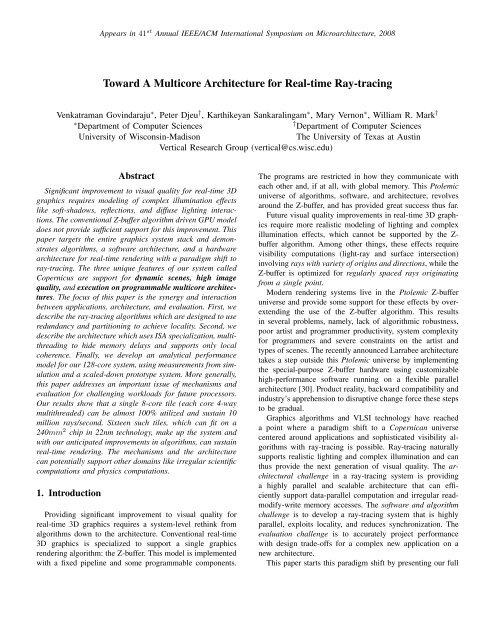
system design called Copernicus, outlined in Figure 1. Copernicusincludes several co-designed hardware and softwareinnovations. Razor, the software component of Copernicus, isa highly parallel, multigranular (at the coarse grain it per<strong>for</strong>msdomain decomposition and in the fine grain it traces multiplerays), locality-aware ray tracer. The hardware architectureis a large-scale tiled multicore processor with private L2caches only, fine-grained ISA specialization tuned to theworkload, multi-threaded <strong>for</strong> hiding memory access latencyand local cache coherence. In addition to providing a newlevel of image quality, the application-driven approach andprogrammability in Copernicus allows multi-way tradeoffsbetween per<strong>for</strong>mance, image quality, image size, and framesper-second.In a game-specific environment, collision detection,approximate physics simulations and scene managementcan also be per<strong>for</strong>med by the rendering system.To evaluate Copernicus, we developed a customized analyticmodel seeded with inputs and validated by a scaledprototype and a full system simulator. This model capturesthe impact of multi-threaded execution and memory accessconflicts. We estimate a 16-tile chip, with 8 cores in a tile,can fit on 240mm 2 chip at 22nm technology. When runningat 4GHz, this system can sustain real-<strong>time</strong> frame-rates <strong>for</strong>realistic benchmarks, rendering up to 74 million rays persecond over all, and 10 million rays per second in a tile.The four main contributions of this paper are: 1) thefirst complete full system single-chip design <strong>for</strong> high qualityreal-<strong>time</strong> rendering of dynamic scenes using ray-<strong>tracing</strong>with effects like soft shadows; 2) an architecture that isa realistic trans<strong>for</strong>mation path <strong>for</strong> graphics hardware from“specialized” embarrassingly-parallel architectures to flexiblehigh-throughput parallel architectures; 3) a detailed characterizationand analysis framework <strong>for</strong> a future computationworkload; 4) and a customized analytic model that capturesthe impact of multi-threading and memory access conflicts.The rest of this paper is organized as follows. Section 2describes our algorithms and software architecture. Section 3presents a detailed characterization of this workload andSection 4 describes our architecture design. Section 5 presentsour per<strong>for</strong>mance results and Section 6 discusses related work.Section 7 discusses synergy between application, architecture,and evaluation, and extensions beyond graphics, and Section 8concludes.Figure 1. Copernicus system overview and comparison to Z-buffer2. Graphics algorithms and RazorOne of the big challenges <strong>for</strong> future architectures is the architecture/applications“chicken and egg” problem. To studyarchitectural tradeoffs, we need an application optimized <strong>for</strong>that architecture. For many consumer applications, futureworkloads may not exist yet <strong>for</strong> any architecture, becauseadditional per<strong>for</strong>mance is used to increase quality, ratherthan reduce <strong>time</strong> to solution. To overcome this “chicken andegg” problem <strong>for</strong> our ray-<strong>tracing</strong> based system, we explicitlydesigned to explore future graphics capabilities on futuremulticore architectures. For a full discussion of the graphicsalgorithms refer to [5]. Below, we provide an overviewemphasizing the workload and architecture interaction.Basics: <strong>Ray</strong>-<strong>tracing</strong> is a technique <strong>for</strong> generating images bysimulating the behavior of light within a 3D scene by typically<strong>tracing</strong> light rays from the camera into the scene [25]. Ingeneral two types of rays are used. Primary rays are tracedfrom a particular point on the camera image plane (a pixel)into the scene, until they hit a surface, at a so-called hit point.Secondary rays are traced from a hit point to determine howit is lit. Finally, to determine how the surface material appearstexture lookups and shading computations are per<strong>for</strong>med ator near the hit point.Razor description: Our ray-<strong>tracing</strong> system, called Razorsupports dynamic scenes (i.e. scenes that change geometrywith user interaction like breaking a wall in a game) with highquality effects like soft shadows and defocus blurring using ageneral visibility model. As shown in Figure 1, it implementsvisibility using a spatial data structure (specifically a kdtree)built <strong>for</strong> every frame, unlike a traditional ray-tracerwhich does this once as part of pre-processing. Razor usescoarse-grain concurrency by domain decomposition of framesinto “chunks”, and fine-grained concurrency by packet-<strong>tracing</strong>many rays simultaneously as shown in Figure 1. Materialshading computations are decoupled from intersection computationssince they differ significantly.Razor analysis: The spatial data structure (kd-tree) and perframerebuild allows objects to move in the scene. However,this requires fine granularity read-modify-write support inthe memory. The explicit chunk-based concurrency in Razorallows each processor to build its own copy of the spatialdata structure, avoiding global synchronization. The storageoverhead of “replication” is relatively small because the2
primary rays assigned to different chunks access mostlynon-overlapping parts of the data structure. Secondary rayscould disrupt this behavior, but empirically we found theirimpact to be small. Decoupling material shading from intersectionand fine-grained packet-<strong>tracing</strong> provides fine-graindata-parallelism.From analysis of the algorithm, we derive the hardwarechallenges <strong>for</strong> our Copernicus system: (a) Large computationdemand requiring a highly parallel architecture, (b) Key datastructures are modified or rebuilt every frame, with this workdone on-demand rather than in a temporally separate phase,(c) These data structures are irregular, and thus difficult tosupport with software managed caches, (d) The size of thekey data structures is large (on the order of a few gigabytes),so the architecture must exploit locality.Sofware implementation: To drive the algorithms and architecturalexploration we developed a fully functional implementationof Razor. Razor is parallelized using multithreading,with one main thread and worker threads <strong>for</strong> eachprocessor core. Primary rays are organized into 2D screenspace“chunks” which are placed onto a work queue andmapped to worker threads as shown in Figure 1. Chunks aresized to capture significant memory-access locality withoutdisrupting load-balance. We optimized Razor using SSEintrinsics with the Intel Compiler running on Windows, todrive the algorithm development. For architecture studies,we implemented a flexible version of Razor that compileson Gcc/Unix which we have tested on x86/Linux andSparc/Solaris. It uses our cross-plat<strong>for</strong>m SSE library thatimplements the intrinsics using C with the native compilergenerating instructions available in the machine. While Razoris designed <strong>for</strong> future hardware, it runs on today’s hardwareat 0.2 to 1.1 frames/sec on a commodity 8-core (2 socketx quad-core) system and is robust enough to support scenesextracted from commercial games.Related work: <strong>Ray</strong>-<strong>tracing</strong> has been studied <strong>for</strong> a long<strong>time</strong> [31], [39]. Only recently researchers have begun toexamine its potential <strong>for</strong> interactive rendering with systemstargeted at today’s hardware [23], [1], [9], ASICs [33],[35], [40], FPGAs [36], or distributed clusters [28], [38].In general, these systems are not representative of futuresystems in one or more of the following ways: They donot address the parallel scalability of single-chip manycorehardware; they compromise image quality and functionalityso that the workload is simpler than that of future real-<strong>time</strong>ray-<strong>tracing</strong> workloads; or the workload is restricted to theeasier case of static or rigid-body scenes. The Manta system[2] is a notable partial exception – its scalability on largemulti-chip SGI shared memory machines has been studied.3. Workload characterizationThis section presents a detailed characterization of our renderingsystem, focusing on the parallelism, memory behavior,computation, and sensitivity to input. We analyze both theunoptimized and x86-optimized implementations to drive ourarchitecture design. Unlike simulation-only characterizationor back-of-envelope estimates, we use per<strong>for</strong>mance countermeasurements on existing systems to motivate newer systems.Such a methodology is essential to break out of the “chickenand egg” application/architecture problem.Infrastructure: For per<strong>for</strong>mance tuning and application developmentwe used two scaled-prototype systems: namelya dual-socket quad-core Intel processor (Clovertown - IntelXeon E5345 2.33GHz) that allows us to examine 8-wayscalability and a Niagara system (Sun-Fire-T200) that allowsus to examine 32-way scalability. In addition, these two systemsallow us to compare out-of-order processing to in-orderprocessing, and the benefits of simultaneous multi-threading.We used PAPI-based per<strong>for</strong>mance counter measurement [20],gprof [7], Valgrind [21], and Pin [26] to characterize Razor. Inaddition, we used the Multifacet GEMS simulation [18] environment<strong>for</strong> sensitivity studies. Table 1 briefly characterizesour benchmark scenes which are from game and game-likescenes and representative of real workloads.3.1. ParallelismFigure 2 characterizes Razor’s parallelism behavior usingour prototype systems and shows it has abundant parallelism.Figure 2a shows per<strong>for</strong>mance on a single core (in-orderNiagara) as more threads are provided. We can see nearlinearspeedup going from 1 to 4 threads. Our analyticalmodel of processor utilization (details in section 5.2) andsimulation results show that at 1-thread the processor isonly 20% utilized and hence executing 4 threads providesspeedup. This parallel speedup shows that the working setsize of each thread is small enough to fit in the L2 cache andmultithreading hides the latency of the L1 misses.Figure 2b and 2c show parallel scalability as the amountof resources (# cores) is increased from 1 core to 8 cores:speedups are relative to the baseline 1-core. Niagara runningin this configuration under-utilizes the cores because only onethread is assigned to each core. Razor exhibits near-linearspeedups, and a 16-thread configuration with two threads percore shows similar behavior. The Clovertown system showslinear speedup up to 4 cores and beyond that its front-sidebus based communication hinders parallel speedups. Niagaraspeedups <strong>for</strong> this application require some explanation, sinceit has one FPU per chip. Our SSE library when executednatively on a SPARC machine like Niagara does not haveaccess to real SIMD registers. Due to gcc’s aliasing analysis,these variables are not register-allocated and instead are inmemory. Hence, every intrinsic call, even though inlinedresults in 8 memory instructions at least, thus making theFPU under-utilized. On our simulator, we effectively emulateSIMD registers and operations which are incorporated intoour instruction mix analysis and per<strong>for</strong>mance estimation.3
43.532.521.5CourtyardFairy<strong>for</strong>estForestJuarezSaloon8765432CourtyardFairy<strong>for</strong>estForestJuarezSaloon65432CourtyardFairy<strong>for</strong>estForestJuarezSaloon12 412 4 6 812 4 6 8(a) Niagara 1-core with multiple threads per core (b) Niagara multiple cores (1 thread per core) (c) Clovertown multiple cores(1 thread per core)Figure 2. Razor parallelism. For all graphs X-axis is number of threads and Y-axis is speedup.Memory footprint54.543.532.521.51CourtyardFairy<strong>for</strong>estForestJuarezSaloon4 8 12 16 20 24 28 32# Threads(a) Memory growth with threads measuredon Clovertown. (Same trend on Niagara)Miss rate (%)65432104K 32K 128K 1M 8M 64M 256MCache size(b) Working set size - measured throughsimulationFigure 3. Razor memory behavior.CourtyardFairy<strong>for</strong>estForestJuarezBenchmark L1 miss L2 missSaloonrate % rate %Courtyard 1.4 2.2Fairy<strong>for</strong>est 1.5 4.4Forest 1.9 5.7Juarez 1.5 26.1Saloon 1.5 5.8(c) Locality measured from simulatingNiagara-like configuration.and unique memory references using Pin. The sixth rowin Table 1 shows the average unique memory referencesper sample. Across all the scenes, the number of uniqueaddresses (measured at cache line size granularity) is between15000 and 80000 <strong>for</strong> 100 million instructions, while the totalreferences is between 45 million and 50 million. This showshigh spatial locality in the kd-tree is indeed achieved by thecoherence between primary rays and the localized nature ofsecondary rays. Figure 3c shows our measured L1 and L2data cache miss rates derived from simulating a Niagara-likeconfiguration. Since the working set is quite small, we cansee that the miss rates are quite low.Observation 4: The instantaneous working set of the applicationis quite small.Observation 5: The data traversed is scene dependent andis fundamentally recursive and hence static streaming techniquescannot capture the working set.3.3. ComputationTable 2 describes the basic computation characteristics.Columns 2 through 6 show the breakdown of computationin terms of different functional units used. The code is verymemory intensive with only a small fraction of branches.However, most of these branches are data-dependent andhence cannot be supported efficiently with just predication.We measured branch prediction accuracy in our Clovertownprototype and found it to be greater than 97% which showsa 2-level predictor learns the correlations well (Niagara hasno branch prediction). Columns 7 and 8 show IPC whichaverages close to 1 on the 3-issue out-of-order Clovertown,and about 0.4 on the in-order Niagara, showing limited ILP.Table 1 shows our coarse-grained analysis of computation.Six functions (lines 11 through 16 in Table 1) contributemore than 80% of the total computation <strong>time</strong>. Most ofthe computation <strong>time</strong> is spent in the top three functionswhich take a packet of rays and traverse the kd-tree datastructure. As needed, they call other functions to lazilybuild the tree during traversal. When rays do intersect aleaf node, Intersect<strong>Ray</strong>KDLeaf is called to traverse asmaller spatial data structure <strong>for</strong> a tessellated surface patch.As needed, it, in turn, calls another function to lazily createthe geometry. Actual ray/triangle intersection is per<strong>for</strong>med bythe fifth and sixth most common functions which prepare thepair of triangles to interpolate from discrete levels of detailand per<strong>for</strong>m the actual intersection test on the interpolatedtriangle.Observation 6: There is limited fine-grained instruction-5
Scene Instruction Mix(%) IPC SpeedupALU FP LD ST BR N C OOO SSEcourtyard 42 32 14 8 2 0.4 1.01 3.4 3.5fairy<strong>for</strong>est 46 26 13 8 4 0.3 1.03 3.4 3.1<strong>for</strong>est 53 18 15 5 7 0.4 1.00 2.6 4.2juarez 49 18 12 12 6 0.4 1.05 3.3 3.7saloon 48 22 13 9 6 0.3 1.04 3.7 3.4Table 2. Razor computation characteristics. Instruction mixdata shown is <strong>for</strong> Niagara SPARC code with SIMD emulation.Pin-based x86 instruction mix is similar.Coretype# Cores Rendering<strong>time</strong>(sec)# Cores Rendering<strong>time</strong>(sec)256KB cache per core Fixed 2MB cache totalOOO ∗ 13 3.7 - 1.5 44 7 - 0.5Inorder + 109 33 - 2.7 167 22 - 1.8Table 3. Simple optimistic scaling of existing designs.Per<strong>for</strong>mance range across the different scenes. ∗ Core2-likecore. + Niagara-like core.level parallelism and significant amount of irregular graphtraversal.Machine-specific optimizations: The last two columns inTable 2 compare per<strong>for</strong>mance across our two prototypesystems, which shows Razor’s sensitivity to out-of-order processingand ISA specialization. To normalize <strong>for</strong> technology,Clovertown system per<strong>for</strong>mance was linearly scaled downby the frequency difference to Niagara. Speedup in thisscaled rendering <strong>time</strong> is compared to Niagara. Adding outof-orderprocessing and increased issue width alone providesan approximate 3X per<strong>for</strong>mance improvement, shown bythe OOO column. Adding SIMD specialization with SSE3instructions and machine specific optimizations (compilationwith gcc -O4 -msse3) provides an additional 3X to 4.2Ximprovement, shown in the last column.Observation 7: Application specific tuning can provide significantper<strong>for</strong>mance improvements <strong>for</strong> Razor.This workload characterization of Razor shows that it ishighly parallel and is thus suited <strong>for</strong> a multicore parallelarchitecture. But it is not trivially data parallel, and while itsmemory accesses are quite irregular, they have good locality.4. <strong>Architecture</strong>Our goal is to build a future system targeted at high qualityscenes at 1024x1024 resolution at real <strong>time</strong> rates implyingrendering <strong>time</strong>s of 0.04 seconds per frame. On average,per<strong>for</strong>mance on our 8-core system ranges between 17.5 to4 seconds per frame <strong>for</strong> high quality scenes and between 1.1to 0.5 seconds <strong>for</strong> lower quality scenes. Compared to thissystem, we need another 100-fold to 500-fold increase inper<strong>for</strong>mance. While Razor is heavily optimized, we believefurther algorithmic tuning is possible and expect a 10-foldincrease in its per<strong>for</strong>mance and thus our target is 0.4 secondsper frame using the current software. Thus the architectureFigure 4. Copernicus hardware organization.must provide 10- to 50-fold better per<strong>for</strong>mance than our 8-core prototype system. We pick a design point fives years inthe future and target 22nm technology, a frequency of 4GHzwhich should be feasible with relatively modest timing andpipelining optimizations, and die area of 240mm 2 .Simply scaling existing systems has three main problems:a) area constraints limit the per<strong>for</strong>mance that can be achieved,b) the on-chip memory system and interconnect designbecomes overly complex, and c) general-purpose solutionsdo not exploit several opportunities <strong>for</strong> application-specifictuning. Table 3 summarizes the area and per<strong>for</strong>mance thatcan be sustained by simply scaling and integrating morecores on chip. The first method assumes the cache capacityis scaled such that there is always 256KB of L2 cache percore and the second method provides a total of 2MB <strong>for</strong>all the cores. Examining the OOO (out-of-order) cores, theyare simply too large to provide the kind of parallel speeduprequired. The in-order Niagara-like cores, while area efficient,do not have support <strong>for</strong> fine-grained data-level parallelismand their baseline per<strong>for</strong>mance is too low. Thus neithertechnique provides the per<strong>for</strong>mance required. What is ideallyrequired is Core2-like per<strong>for</strong>mance with the area of an inorderprocessor. Second, existing multicore designs of sharedL2 caches with global coherence don’t scale to hundreds ofcores. Finally, the cumulative L2 miss-rates of all the coresplaces a large burden on the memory system, and the fixed2MB L2 cache will face severe congestion and require severalports. In this section, we describe the hardware architectureof our Copernicus system which exploits application behaviorand fuses existing technologies and develops new techniques.4.1. High-level organizationWe propose a 2-level multicore organization with a setof cores and a shared L2 cache <strong>for</strong>ming a tile. The fullchip consists of multiple tiles (caches private to tile) andI/O controllers. Figure 4 shows this organization and wespecifically investigate a 16-tile, 8 cores per tile configuration.Figure 1 shows the software mapping to the architecture.The 2D screen-space is partitioned and into at least as many“blocks” as there are tiles, and coarse grained parallelism is6
achieved by providing a “block” to each tile. These “blocks”are further broken into “chunks”, the granularity at whichRazor operates via its chunk work queue. Chunks are sizedto capture significant memory-access locality, made largeenough to amortize the cost of communication with the workqueue, and small enough to not cause load-imbalance. Withina “chunk”, each core ray-traces packets of up to 16 light raystogether exploiting fine-grained parallelism.4.2. Core organizationEach core in a tile resembles a conventional programmablecore but with specializations <strong>for</strong> processing-intensive workloadssuch as graphics rendering, by matching the memory intensityand computation requirements. Since it is not possibleto keep the entire working set in the L1 cache, techniques tohide this latency are required. For this workload, out-of-orderprocessing is not area or power efficient, and since there isabundant parallelism, we use simultaneous multi-threading tohide memory latency. Unlike GPUs, which require hundredsof threads per core to hide main memory latency, we expectgood L2 cache behavior and thus require only modest amountof SMT - between 2 and 8 threads per core. Razor is apacket ray-tracer and exhibits fine-grained parallelism in rayprocessing. In fact this is fine-grained data-level parallelismbecause the same graph traversal and surface-ray intersectionoperations are computed <strong>for</strong> every ray in a packet. To supportthis efficiently, each core also includes a 4-wide SIMD unit.Our initial design explored in this paper uses the Intel SSEintrinsics <strong>for</strong> our SIMD unit as the software was already tuned<strong>for</strong> it.In addition, each tile includes an “accelerator” that is integratedinto the execution pipeline, although this accelerator isnot currently used by our software. Long latency and highlyspecialized tasks could be routed to this unit by all the coresin a tile. We expect moderately frequent computation likesquare root, trigonometric equations, and light attenuationto be implemented in the accelerator. Having such a sharedper-tile accelerator can provide significant area and powerefficiency, to be explored in future work. In this study, weonly assume an SSE-like unit in every core.4.3. On-chip memory and Memory systemEach tile includes a shared L2 cache that is connectedthrough a cross-bar to the different cores. The differenttiles are connected through a mesh-network that eventuallyroutes requests to the integrated memory controllers. Ourcharacterization work suggests that in the worst case, a singleframe touches a total of 122MB to approximately 600MBworth of cache lines (Table 1, row 4). Since our systemrebuilds its spatial data structures every frame, we anticipate aworst case memory bandwidth of 600MB * 25 frames/second= 15GB/second. Detailed memory system tuning is beyondthe scope of this work and in this study we use a conservativeanalytical model to estimate memory system contention.Our L1-L2 cache is designed <strong>for</strong> simplicity and followsa simple cache coherence protocol. The L1 caches are writethrough and the L2 caches maintain a copy of the L1 tagsand keep track of which core in a tile has a copy of anygiven L1 line. A significant simplification in our designwhich allows us to scale to the order of 128 cores is thatthe hardware provides no coherence guarantees across tiles.This abstraction works <strong>for</strong> this application but how well thisextends to other applications is an open question. Giventechnology trends of wire-delays and storage, this tradeoffof redundancy over synchronization is a unique design pointthat has not been explored in the past.5. ResultsThis section evaluates the Copernicus system. We use thefive benchmark scenes described in Table 1 and a full systemsimulator and analytical models <strong>for</strong> per<strong>for</strong>mance estimates.We first present baseline per<strong>for</strong>mance that is achievable ona single-core, and then study per<strong>for</strong>mance improvementsthrough multi-threading and parallelism from multiple coreson a tile. Finally, we present full chip results using theanalytical model.5.1. MethodologySimulator: We customized Multifacet GEMS to model asingle tile with in-order issue and varying level of multithreadingsupport. The simulator is configured with a 32KB,2-way set associative L1 data and instruction cache. Theshared L2 cache is set to be 2MB, and 4-way set associative.We use the default GEMS functional unit latencies and a 2-level branch prediction scheme with a total of 100Kbits of targetand history. Thread-scheduling logic is strict round-robinbetween the threads that are not waiting on a L1 cache miss.Razor is compiled <strong>for</strong> a sparc-sun-solaris2.10 target with ourC-only SSE intrinsics library. The implementation triggers atrap in GEMS, and we simulate 4-wide SIMD execution ofthese instructions, ignoring the functional instruction stream.Datasets: Rendering a full frame of a complete scene (ormultiple scenes) is truly representative of per<strong>for</strong>mance but thesimulation overhead <strong>for</strong> this is too high - a single frame isabout 50 billion instructions. Thus it is necessary to simulatea subset of a frame, but taking care to account <strong>for</strong> thesignificant amount of intra-scene heterogeneity. For example,background regions require little computation, whereasregions along a shadow boundary require lots of computation.To account <strong>for</strong> this heterogeneity, we simulate four randomlyselected regions <strong>for</strong> all the benchmarks, and <strong>for</strong> every regionwe simulated the smaller of 200 million instructions or 128primary rays (and all of their accompanying secondary rays)per thread. The per<strong>for</strong>mance we report is the average acrossthese regions.7
Metrics: It is easier to compare rendering systems andunderstand tradeoffs by measuring total rays rendered persecond rather than frames/second. In the remainder of thispaper we use total rays/sec to report per<strong>for</strong>mance and IPCto report processor utilization. Razor automatically generatessecondary rays as the primary rays traverse the scene and allthe scenes used in this study require 40 million total rays torender the full scene (1024x1024 resolution, with 8 primaryrays per pixel and 4 secondary rays per primary ray <strong>for</strong> ourscenes). A real-<strong>time</strong> rate of 25 frames-per-second translatesto 1,000 million total rays/sec. Other contemporary systemslike Cell’s iRT sustain roughly 46 million total rays/second onstatic game-like scenes with shading [1]. Note that we targetsignificantly higher image quality. We assume a ten-foldimprovement in Razor’s algorithms is possible, and henceour goal with this architecture is to sustain 100 million totalrays/sec on the current Razor software.Limitations: In this work, we abstract away the details ofthe operating system and thread scheduling. Our system simulationrelies on the operating system’s scheduling heuristics.We did not observe large load imbalances. The number ofthreads created is under application control and we set it tomatch number of threads the hardware supports.5.2. Analytical modelMicroarchitecture simulation of the full architecture is infeasible.So, we developed a new customized analytical modelthat takes fundamental input parameters which characterizethe system and workload, and projects per<strong>for</strong>mance - at scale- <strong>for</strong> a variety of system design alternatives.The model accounts <strong>for</strong> all non-ideal parallel scaling ofthe workload on the hardware. More specifically, the modelcaptures the longer communication latencies to main memoryand three types of contention: (1) the intra-core contentionamong threads <strong>for</strong> the processor core, (2) the intra-tilecontention <strong>for</strong> the shared L2 caches, and (3) the intra-chipcontention <strong>for</strong> main memory. Since each tile has its own k-dtree, synchronization delays <strong>for</strong> nodes in the tree, which arenegligible in the single-tile case, do not increase with moretile.The model provides insights into the impact of pipelinestalls within a thread, processor stalls in the context of multiplethreads, and contention <strong>for</strong> memory resources. Accuratemodeling of the thread contention <strong>for</strong> core processor cyclesrequires modeling the impacts of instruction dependencesas well as multi-issue within the core pipeline. This, inturn, required new fundamental model input parameters andnew model equations. These new model customizations areapplicable to evaluating other applications on other futuremulti-threaded multicore architectures, and to our knowledgehave not previously been developed.Since our processors are in-order, the main parameters thatdictate the processor’s execution are the L1 and L2 cachemisses and the register dependences between instructions.The dependences are measured in terms of the distributionof the distance from each instruction to its first dependentinstruction. We outline the details of the model in three stages.Pipeline stalls: In the first stage, the fundamental workloadinstruction mix parameters given in Table 2 are used togetherwith the functional unit latencies to estimate, <strong>for</strong> each instructiontype i, the average <strong>time</strong> that the next instructionwill stall due to either a dependence or a shorter latency. Welet f i denote the fraction of instructions that are of type i,L i denote the instruction pipeline length <strong>for</strong> instruction typei, and d 1 denote the fraction of instructions with distance tofirst dependent instruction that are equal to one. Letting t idenote one (<strong>for</strong> the cycle that type i begins execution) plusthe average stall <strong>time</strong> <strong>for</strong> the next instruction, we capture thefirst-order pipeline stall effects <strong>for</strong> this workload as follows:∑t i = 1 +f j (L i − L j )+(∑j:L j=L if j + f branch ) × d 1 × (L i − 1)Multi-threading: In the second stage, we use the aboveequation to first compute t, the sum of t i weighted by f i , andthen to compute the distribution of the number of instructionsthat begin executing in each cycle. This latter quantity is afunction of the number of threads that are being interleaved(k), and the instruction issue width. For k threads on a singleissue core, the fraction of cycles that an instruction is issuedcan be modeled by, 1 − ( 1 − 1 t) k. In this case, r(k), the ray<strong>tracing</strong> rate with k threads as compared with one thread is theratio of this quantity to 1/t, since 1/t is the fraction of cyclesthat an instruction is issued when a single thread executes ona single-issue core. It is similarly straight<strong>for</strong>ward to developthe execution rates <strong>for</strong> a 2-issue core.Memory system: In the final stage of model development, weincorporate the impact of contention <strong>for</strong> L2 and main memorybanks. Here we use well-established queuing networkapproximate mean value analysis (AMVA) techniques [15].Each cache and main memory bank is represented by simplesingle-server queues with deterministic service <strong>time</strong>s, routingof cache misses is represented by visit counts to the applicableL2 cache and main memory banks, interconnection networklatencies are represented by delay centers, and each core isrepresented by a variable-rate queue to capture the executionrate as a function of the number of threads that are executing(and not waiting on a cache miss). Equations <strong>for</strong> such queuingsystems are available <strong>for</strong> example in [15]. Such equationshave proven to be accurate in other parallel system architectureswith a single-thread per core [32]. A key contributionof this paper is the validation of the extensions to estimatepipeline stalls and multi-threading.Using this fairly simple system of equations, we explore the8
Scene 1-Thread 2-Threads 4-ThreadsIPC Perf. IPC Perf. IPC Perf.S M S M S MSingle core, 1-issue processorcourtyard 0.45 0.46 280 0.82 0.71 515 0.97 0.92 605fairy<strong>for</strong>est 0.39 0.43 480 0.73 0.69 900 0.97 0.91 1200<strong>for</strong>est 0.43 0.52 125 0.86 0.78 255 0.97 0.95 285juarez 0.34 0.38 200 0.69 0.70 400 0.97 0.93 565saloon 0.38 0.43 360 0.73 0.70 590 0.97 0.92 915Single core, 2-issue processorcourtyard 0.7 440 1.1 0.84 690 1.7 1.5 1065fairy<strong>for</strong>est 0.59 730 0.94 0.72 1160 1.7 1.2 2100<strong>for</strong>est 0.64 190 1.2 1.03 355 1.9 1.6 560juarez 0.48 280 0.9 0.80 525 1.7 1.4 990saloon 0.56 530 0.98 0.80 925 1.7 1.4 1605One Tile - 8 cores per tile, 1-issue processorscourtyard 3.7 3.7 2280 7.0 5.7 4375 7.8 7.4 4875fairy<strong>for</strong>est 3.6 3.4 4445 7.2 5.5 8890 7.8 7.3 9630<strong>for</strong>est 3.8 4.1 1120 7.2 6.3 2125 7.9 7.6 2330juarez 3.7 3.5 2150 7.4 5.6 4300 7.8 7.4 4535saloon 3.6 3.6 3395 7.1 5.6 6700 7.8 7.3 7370One Tile - 8 cores per tile, 2-issue processorscourtyard 5.0 3125 8.8 6.7 5500 14.8 11.8 9250fairy<strong>for</strong>est 4.9 6050 8.8 6.1 10865 14.6 10.8 18025<strong>for</strong>est 5.3 1565 8.9 8.3 2625 14.6 13.3 4305juarez 4.8 2790 9.0 6.7 5235 14.6 14.8 8490saloon 5.0 4715 8.2 6.4 7745 14.3 11.5 13510Table 4. Single tile model validation. Column S: simulatorresults. Column M: analytical model results. Per<strong>for</strong>mancemeasured in 1000s of rays/sec from simulator.design space of numer of tiles, cores, threads-per-core, issuewidth,and scene-specific cache miss rates, and provisioningof how many memory banks. Other model-derived insightsinclude:Model Insight 1: Stalls due to dependences have small impacton per<strong>for</strong>mance.Model Insight 2: Stalls due to L1 cache misses have a largeimpact on per<strong>for</strong>mance.Model Insight 3: Significant speedup is possible with multithreadingand two-issue cores, but these speedups come atthe cost of significant demands <strong>for</strong> memory bandwidth.5.3. Per<strong>for</strong>mance resultsWe first examine single-tile per<strong>for</strong>mance from simulationand the model to validate our model. We then examine thefull system per<strong>for</strong>mance and total chip area.Single-tile and model validation: Table 4 shows the per<strong>for</strong>manceacross the different processor configurations we study,which all assume a 4GHz clock frequency. We specificallyexamine the sensitivity to multi-threading and issue width.For each SMT configuration, there are three columns: IPCfrom the simulator, IPC from the model, and per<strong>for</strong>mance(total rays per second in 1000s). Considering the single core,1-thread configuration, we can see that a single thread is ableto utilize less than 50% of the processor <strong>for</strong> almost all thescenes, and with 2 threads close to 80% is utilized (IPC is0.69 to 0.83), and reaches almost 100% at 4 threads (IPC is0.97). Our analytical model predicts per<strong>for</strong>mance accurately<strong>Ray</strong>s/sec (millions)10090807060504030201016 banks24 banks32 banks48 banks64 banksIdeal2 4 6 8 10 12 14 16# TilesFigure 5. Per<strong>for</strong>mance sensitivity to memory bandwidth. 1-issue, 4-way SMT core. [Courtyard scene].(IPCs in the M column) and is off by less than 2%. Thesecond set of rows, show per<strong>for</strong>mance <strong>for</strong> a 2-issue processor.The 1-thread and 2-thread configurations per<strong>for</strong>m moderately,and we see large benefits when executing 4 threads with IPCsranging <strong>for</strong> 1.7 to 1.9. The model errors are slightly higher.The last two sets of results are <strong>for</strong> a full tile consisting of 8cores and we show aggregated IPC from all cores. The singleissue cores are more efficient and come close to executing at100% utilization with 4 threads with IPCs reaching 8. The deviationof the analytical model from simulation is now higher.Overall though, it is consistently more conservative than thesimulator because of how it models L2-bank contention.The IPC by itself is a meaningless number when determiningper<strong>for</strong>mance <strong>for</strong> the scenes, as each scene requiresdifferent instructions and amount of work. Instead, total raysper second is a better measure. Our target <strong>for</strong> real-<strong>time</strong> ratesis 100 million total rays/second using all the tiles. Table 4shows that a single tile with single-issue and four threads percore can sustain between 2.3 million and 9.6 million rays persecond.Full system design exploration: To obtain full-chip per<strong>for</strong>mance,we used our full system analytical model, whichmodels memory and on-chip network contention. To completethe chip design, we need to determine memory systemconfiguration and interconnection network.Memory: The model can determine memory bandwidth requiredand the number of memory banks so that enoughoverlapping requests can be serviced. We used the modelto analyze our different workloads by varying the numberof tiles and number of memory banks. Figure 5 shows thisanalysis <strong>for</strong> one benchmark courtyard <strong>for</strong> a single-issue 4-way multithreaded core, and the behavior was largely similar<strong>for</strong> all benchmarks. With 64 banks, the per<strong>for</strong>mance is within50% of ideal (no contention). This gives us a realistic systemof 4 DIMMs with 16 banks each.Interconnection network: Most of the contention <strong>for</strong> thisworkload is at the memory system and not the mesh networkon chip, since assuming a shared bus to model worst casenetwork contention, results in the memory system being the9
Core type Per<strong>for</strong>mance (millions rays/sec) #Tiles #CoresIdeal <strong>Real</strong>isticAve. Range Ave. Range1-issue, no SMT 37 16-62 42 19-66 16 1281-issue, 4 threads 82 33-138 43 13-74 16 1152-issue, no SMT 34 15-57 26 12-41 10 782-issue, 4 threads 82 36-137 41 13-70 8 65Table 5. Full system per<strong>for</strong>mance and area <strong>for</strong> all scenes.We recommend 1-issue, 4 threads as the best configuration.bottleneck and not the network.Full system per<strong>for</strong>mance: With the number of memorybanks specified, our full system model can make per<strong>for</strong>manceprojections <strong>for</strong> different core configurations and scenes whichare shown in Table 5 as an average and range across our fivebenchmark scenes. Columns two and three show “ideal” per<strong>for</strong>manceachieved by naively scaling the per<strong>for</strong>mance <strong>for</strong> onetile to 16 tiles (or as many that will fit), ignoring contention<strong>for</strong> shared resources. Columns four and five show realisticper<strong>for</strong>mance with the 4-DIMM memory. Our conservativememory model projects that we can sustain between 13 and74 million rays/second, and the ideal model suggests 33 to138 million rays/second.Full system area analysis: Using die-photos of other processorswe built an area model <strong>for</strong> the tiles and the full chip.For overheads of multi-threading, we use methodology fromacademic and industry papers on area scaling [19]. The area<strong>for</strong> our baseline 1-issue core is derived from a Niagara2 corescaled to 22nm, and we assume a 12% area overhead <strong>for</strong>multi-threading <strong>for</strong> 2-threads, and additional 5% per thread.In our area analysis, the additional area of the 4-wide FPUcompared to Niagara2’s FPU is ignored. We assume an 110%overhead when going from 1-issue to 2-issue, since in thismodel we double the number of load/store ports also andhence the L1 cache sizes. The cache size is fixed at 2MB <strong>for</strong>all designs and this includes the cross-bar area between thecores and the cache. Columns 6 and 7 in Table 5 show thenumber of cores of each type that will fit on a 240mm 2 chip.With single-issue cores, we can easily fit 16 tiles, and abouthalf with two issue cores.Summary: Overall, going to dual issue does not providesignificantly higher per<strong>for</strong>mance and single-issue, 4-way multithreadedcores seem ideal. Single-issue cores without SMTseem to match the 4-way SMT cores at the chip-level, becauseof insufficient memory bandwidth to feed the threads. Atthe chip-level, memory bandwidth is the primary bottleneck.While our final per<strong>for</strong>mance results do not outright exceedthe required 100 million rays/second <strong>for</strong> every scene, theflexibility and potential <strong>for</strong> further architectural optimizationsshow this is a viable system.6. Related workRecently, a few application-driven architectures have beenproposed. Yeh et al. have proposed ParallAX, an architecturespecialized <strong>for</strong> real-<strong>time</strong> physics processing [42]. Hugheset al. recently proposed a 64-core CMP <strong>for</strong> animation andvisual effects [10]. Kumar et al. have proposed an architecturecalled Carbon that can support fine-grained parallelism<strong>for</strong> large scale chip-multiprocessors [14]. Yang et al., describea scalable streaming processor targeted at scientificapplications [41]. Clark et al. have proposed a techniquecalled liquid SIMD that can abstract away the details of thedata-parallel hardware [4]. Sankaralingam et al. developeda methodical approach <strong>for</strong> characterizing data parallel applicationsand proposed a set of universal mechanisms <strong>for</strong>data parallelism [29]. All these designs follow the flow ofworkload characterization of an existing application drivingthe design of an architecture. Our work is different in tworespects. First, we co-design future challenge applicationsand the architecture to meet the application per<strong>for</strong>mancerequirements. Second, we provide a more general purposearchitecture and new quantitative tools to support the designprocess. Embedded systems use similar hardware/softwareco-design but <strong>for</strong> building specialized processors and in muchsmaller scale. <strong>Architecture</strong>-specific analytical models havebeen applied <strong>for</strong> processor pipelines to analyze per<strong>for</strong>manceand power [22], [37], [13], [34], [43], [8], [27]. These modelshave also been used <strong>for</strong> design space exploration and rapidsimulation [12], [11], [16], [3], [6], [24].7. Discussion and Future workBuilding efficient systems requires that the software andhardware be designed <strong>for</strong> each other. Deviating both hardwareand software architectures from existing designs poses aparticularly challenging co-design problem. The focus of thispaper has been the co-design of the software, architecture, andevaluation strategy <strong>for</strong> one such system: a ray-<strong>tracing</strong> basedreal-<strong>time</strong> graphics plat<strong>for</strong>m that is fundamentally differentfrom today’s Z-buffer based graphics systems.Our software component (Razor) was designed to allowgraphics and scene behavior to be exploited by hardwarevia fine-grained parallelism, locality in graph traversal,good behavior of secondary rays, and slow growthin memory by virtue of kd-tree duplication. To solve theapplication/architecture “chicken-and-egg” problem, we implementedRazor on existing hardware, in our case SSEacceleratedx86 cores and built a prototype system usingavailable technology with effectively eight cores. This prototypeallowed us to per<strong>for</strong>m detailed application characterizationon real scenes, something impossible on simulationand meaningless without an optimized application.Closing the development loop with design, evaluation andanalysis of software’s behavior on our proposed hardwarearchitecture was accomplished via a novel analytical modelthat provided intuition both <strong>for</strong> the architecture and theapplication. For example, an important application design10
question was to decide whether to duplicate or share the kdtreedata structure. Our 8-core prototype hardware systemdoes not scale and our simulator <strong>for</strong> proposed hardware is tooslow to run the full application to completion. Only the modelcould reveal that duplication overhead is manageable, thusrelaxing coherence requirements <strong>for</strong> the architecture. To developthe model, we combined data gathered on the optimizedprototype using tools like Pin and Valgrind with simulationbasedmeasurements of cache behavior and instruction frequency.With this co-designed approach, we have shownthe ray<strong>tracing</strong>-based Copernican universe of application andgeneral visibility-centric 3D graphics is feasible. However,this work represents only a first cut at such a system design;there is more to explore in the application, architecture, andevaluation details.Application: Razor is the first implementation of an aggressivesoftware design incorporating many new ideas, some ofwhich have worked better than others. With further iterativedesign, algorithm development, and per<strong>for</strong>mance tuning, webelieve a ten-fold per<strong>for</strong>mance improvement in the softwareis possible. Non-rendering tasks in a game environmentand more generally irregular applications map well to thearchitecture and require further exploration.<strong>Architecture</strong>: There is potential <strong>for</strong> further architecturalenhancements. First, the length of basic blocks is quite largeand hence data-flow ISAs and/or greater SIMD width canprovide higher efficiency. Second, ISA specialization, beyondSIMD specialization targeted at shading and texture computationscould provide significant per<strong>for</strong>mance improvements.Improving memory system will be most effective, and 3D integratedDRAM could significantly increase per<strong>for</strong>mance andreduce system power [17]. Physically scaling the architectureby varying the number of tiles, frequency, and voltage scalingto meet power and area budgets provides a rich design spaceto be explored.Evaluation: Our analytical model enables accurate per<strong>for</strong>manceprojections and can even be used <strong>for</strong> sensitivitystudies. In addition, it can be extended to accommodate otherCopernican architectures, like Intel Larrabee [30].Comparison to GPUs and Beyond <strong>Ray</strong>-<strong>tracing</strong>: The processororganization in Copernicus is fundamentally differentfrom conventional GPUs, which provide a primitive memorysystem abstraction while deferring scene geometry managementto the CPU. Architecturally, the hardware Z-bufferis replaced with a flexible memory system and softwarespatial data structure <strong>for</strong> visibility test. This support enablesscene management and rendering in one single computationalsubstrate. We believe GPUs are likely to evolve to such amodel over <strong>time</strong>, potentially with a different implementation.For example, secondary rays could be hybridized with Z-buffer rendering. Our system is a particular point in thearchitecture design space that can support ray <strong>tracing</strong> as oneof potentially several workloads.8. ConclusionsModern rendering systems live in a Ptolemic Z-bufferuniverse that is beginning to pose several problems in providingsignificant visual quality improvements. We show that aCopernican universe centered around applications and sophisticatedvisibility algorithms with ray-<strong>tracing</strong> is possible andthe architecture and application challenges can be addressedthrough full system co-design. In this paper, we describeour system, called Copernicus, which includes several codesignedhardware and software innovations. Razor, the softwarecomponent of Copernicus, is a highly parallel, multigranular,locality-aware ray tracer. The hardware architectureis a large-scale tiled multicore processor with private L2caches, fine-grained ISA specialization tuned to the workload,multi-threading <strong>for</strong> hiding memory access latency, and limited(cluster-local) cache coherence. This organization representsa unique design point that trades off data redundancy andrecomputation over synchronization, thus easily scaling tohundreds of cores.The methodology used <strong>for</strong> this work is of interest in itsown right. We developed a novel evaluation methodologythat combines software implementation and analysis on currenthardware, architecture simulation of proposed hardware,and analytical per<strong>for</strong>mance modeling <strong>for</strong> the full hardwaresoftwareplat<strong>for</strong>m. Our results show that if projected improvementsin software algorithms are obtained, we cansustain real-<strong>time</strong> ray<strong>tracing</strong> on a future 240mm 2 chip at22nm technology. The mechanisms and the architecture arenot strictly limited to ray-<strong>tracing</strong>, as future systems thatmust execute irregular applications on large scale single-chipparallel processors are likely to have similar requirements.AcknowledgmentWe thank Paul Gratz, Boris Grot, Simha Sethumadhavan, theVertical group, and the anonymous reviewers <strong>for</strong> comments, theWisconsin Condor project and UW CSL <strong>for</strong> their assistance, andthe <strong>Real</strong>-Time Graphics and Parallel Systems Group <strong>for</strong> benchmarkscenes and <strong>for</strong> their prior work on Razor. Many thanks to MarkHill <strong>for</strong> several valuable suggestions. Support <strong>for</strong> this researchwas provided by NSF CAREER award #0546236 and by IntelCorporation.References[1] C. Benthin, I. Wald, M. Scherbaum, and H. Friedrich, “<strong>Ray</strong>Tracing on the CELL Processor,” in Interactive <strong>Ray</strong> Tracing,2006, pp. 15–23.[2] J. Bigler, A. Stephens, and S. Parker, “Design <strong>for</strong> parallelinteractive ray <strong>tracing</strong> systems,” in Interactive <strong>Ray</strong> Tracing,2006, pp. 187–196.[3] D. Brooks, P. Bose, V. Srinivasan, M. K. Gschwind, P. G.Emma, and M. G. Rosenfield, “New methodology <strong>for</strong> earlystage,microarchitecture-level power-per<strong>for</strong>mance analysis ofmicroprocessors,” IBM J. Res. Dev., vol. 47, no. 5-6, pp. 653–670, 2003.11
[4] N. Clark, A. Hormati, S. Yehia, S. Mahlke, and K. Flautner,“Liquid SIMD: Abstracting SIMD Hardware usingLightweight Dynamic Mapping,” in HPCA ’07, pp. 216–227.[5] P. Djeu, W. Hunt, R. Wang, I. Elhassan, G. Stoll, and W. R.Mark, “Razor: An architecture <strong>for</strong> dynamic multiresolutionray <strong>tracing</strong>,” Conditionally accepted to ACM Transactions onGraphics (available as UT Austin CS Tech Report TR-07-52).[6] L. Eeckhout, S. Nussbaum, J. E. Smith, and K. D. Bosschere,“Statistical simulation: Adding efficiency to the computerdesigner’s toolbox,” IEEE Micro, vol. 23, no. 5, pp. 26–38,2003.[7] S. L. Graham, P. B. Kessler, and M. K. Mckusick, “Gprof: Acall graph execution profiler,” in SIGPLAN ’82: Symposium onCompiler Construction, pp. 120–126.[8] A. Hartstein and T. R. Puzak, “The optimum pipeline depth<strong>for</strong> a microprocessor,” in ISCA ’02, pp. 7–13.[9] D. R. Horn, J. Sugerman, M. Houston, and P. Hanrahan,“Interactive k-d tree gpu ray<strong>tracing</strong>,” in I3D ’07, pp. 167–174.[10] C. J. Hughes, R. Grzeszczuk, E. Sifakis, D. Kim, S. Kumar,A. P. Selle, J. Chhugani, M. Holliman, and Y.-K. Chen, “Physicalsimulation <strong>for</strong> animation and visual effects: parallelizationand characterization <strong>for</strong> chip multiprocessors,” in ISCA ’07,pp. 220–231.[11] E. Ipek, S. A. McKee, K. Singh, R. Caruana, B. R. de Supinski,and M. Schulz, “Efficient architectural design space explorationvia predictive modeling,” ACM Trans. Archit. CodeOptim., vol. 4, no. 4, pp. 1–34, 2008.[12] T. Karkhanis and J. E. Smith, “Automated design of applicationspecific superscalar processors: an analytical approach,” inISCA ’07, pp. 402–411.[13] ——, “A first-order superscalar processor model,” in ISCA ’04,pp. 338–349.[14] S. Kumar, C. J. Hughes, and A. Nguyen, “Carbon: architecturalsupport <strong>for</strong> fine-grained parallelism on chip multiprocessors,”in ISCA ’07, pp. 162–173.[15] E. Lazowska, J. Zahorjan, G. Graham, , and K. Sevcik,Quantitative System Per<strong>for</strong>mance. Prentice-Hall, 1984.[16] B. C. Lee and D. M. Brooks, “Accurate and efficient regressionmodeling <strong>for</strong> microarchitectural per<strong>for</strong>mance and powerprediction,” in ASPLOS-XII, pp. 185–194.[17] G. H. Loh, “3D-Stacked Memory <strong>Architecture</strong>s <strong>for</strong> Multi-coreProcessors,” in ISCA ’08, pp. 453–464.[18] M. M. Martin, D. J. Sorin, B. M. Beckmann, M. R. Marty,M. Xu, A. R. Alameldeen, K. E. Moore, M. D. Hill, andD. A. Wood, “Multifacet’s General Execution-driven MultiprocessorSimulator (GEMS) Toolset,” Computer <strong>Architecture</strong>News (CAN), 2005.[19] H. M. Mathis, A. E. Mericas, J. D. McCalpin, R. J. Eickemeyer,and S. R. Kunkel, “Characterization of simultaneousmultithreading (smt) efficiency in power5,” IBM Journal ofResearch and Development, vol. 49, no. 4-5, pp. 555–564,2005.[20] S. Moore, D. Terpstra, K. London, P. Mucci, P. Teller,L. Salayandia, A. Bayona, and M. Nieto, “PAPI Deployment,Evaluation, and Extensions,” in DOD-UGC ’03, pp. 349–353.[21] N. Nethercote, R. Walsh, and J. Fitzhardinge, “Building WorkloadCharacterization Tools with Valgrind,” in IISWC ’06, p. 2.[22] D. B. Noonburg and J. P. Shen, “Theoretical modeling ofsuperscalar processor per<strong>for</strong>mance,” in MICRO ’94, pp. 52–62.[23] S. Parker, W. Martin, P.-P. J. Sloan, P. Shirley, B. Smits,and C. Hansen, “Interactive ray <strong>tracing</strong>,” in SIGGRAPH ’05Courses.[24] D. Penry, D. Fay, D. Hodgdon, R. Wells, G. Schelle, D. August,and D. Connors, “Exploiting parallelism and structure toaccelerate the simulation of chip multi-processors,” in HPCA’06, pp. 29–40.[25] M. Pharr and G. Humphreys, Physically Based Rendering:From Theory to Implementation. San Francisco, CA, USA:Morgan Kaufmann Publishers Inc., 2004.[26] “Pin: http://rogue.colorado.edu/wikipin/index.php/downloads.”[27] T. R. Puzak, A. Hartstein, V. Srinivasan, P. G. Emma, andA. Nadas, “Pipeline spectroscopy,” in SIGMETRICS ’07, pp.351–352.[28] E. Reinhard, B. E. Smits, and C. Hansen, “Dynamic accelerationstructures <strong>for</strong> interactive ray <strong>tracing</strong>,” in EurographicsWorkshop on Rendering Techniques, 2000, pp. 299–306.[29] K. Sankaralingam, S. W. Keckler, W. R. Mark, and D. Burger,“Universal Mechanisms <strong>for</strong> Data-Parallel <strong>Architecture</strong>s,” inMICRO ’03, pp. 303–314.[30] L. Seiler, D. Carmean, E. Sprangle, T. Forsyth, M. Abrash,P. Dubey, S. Junkins, A. Lake, J. Sugerman, R. Cavin, R. Espasa,E. Grochowski, T. Juan, and P. Hanrahan, “Larrabee:a many-core x86 architecture <strong>for</strong> visual computing,” in SIG-GRAPH ’08, 2008, pp. 1–15.[31] B. Smits, “Efficiency issues <strong>for</strong> ray <strong>tracing</strong>,” J. Graph. Tools,vol. 3, no. 2, pp. 1–14, 1998.[32] D. J. Sorin, V. S. Pai, S. V. Adve, M. K. Vernon, and D. A.Wood, “”analytic evaluation of sharedmemory parallel systemswith ilp processors”,” in Proc. 25th Int’l. Symp. on Computer<strong>Architecture</strong> (ISCA ’98), 1998, pp. 380–391.[33] J. Spjut, S. Boulos, D. Kopta, E. Brunvand, and S. Kellis,“Trax: A multi-threaded architecture <strong>for</strong> real-<strong>time</strong> ray <strong>tracing</strong>,”in SASP ’08, pp. 108–114.[34] V. Srinivasan, D. Brooks, M. Gschwind, P. Bose, V. V. Zyuban,P. N. Strenski, and P. G. Emma, “Optimizing pipelines <strong>for</strong>power and per<strong>for</strong>mance,” in MICRO ’02, pp. 333–344.[35] E. B. Sven Woop and P. Slusallek, “Estimating per<strong>for</strong>manceof a ray-<strong>tracing</strong> asic design,” in Interactive <strong>Ray</strong> Tracing,September 2006, pp. 7–14.[36] J. S. Sven Woop and P. Slusallek, “RPU: A Programmable <strong>Ray</strong>Processing Unit <strong>for</strong> <strong>Real</strong><strong>time</strong> <strong>Ray</strong> Tracing,” in SIGGRAPH ’05,pp. 434 – 444.[37] T. Taha and D. Wills, “An instruction throughput model ofsuperscalar processors,” in Workshop on Rapid Systems Prototyping’03, pp. 156–163.[38] I. Wald, C. Benthin, and P. Slusallek, “Distributed interactiveray <strong>tracing</strong> of dynamic scenes,” in PVG ’03, p. 11.[39] I. Wald, T. J. Purcell, J. Schmittler, C. Benthin, and P. Slusallek,“<strong>Real</strong><strong>time</strong> <strong>Ray</strong> Tracing and its use <strong>for</strong> Interactive GlobalIllumination,” in Eurographics State of the Art Reports, 2003.[40] S. Woop, G. Marmitt, and P. Slusallek, “B-KD Trees <strong>for</strong>Hardware Accelerated <strong>Ray</strong> Tracing of Dynamic Scenes,” inProceedings of Graphics Hardware, 2006, pp. 67–77.[41] X. Yang, X. Yan, Z. Xing, Y. Deng, J. Jiang, and Y. Zhang, “A64-bit stream processor architecture <strong>for</strong> scientific applications,”in ISCA ’07, pp. 210–219.[42] T. Y. Yeh, P. Faloutsos, S. J. Patel, and G. Reinman, “Parallax:an architecture <strong>for</strong> real-<strong>time</strong> physics,” in ISCA ’07, pp. 232–243.[43] V. V. Zyuban, D. Brooks, V. Srinivasan, M. Gschwind, P. Bose,P. N. Strenski, and P. G. Emma, “Integrated analysis of powerand per<strong>for</strong>mance <strong>for</strong> pipelined microprocessors,” IEEE Trans.Computers, vol. 53, no. 8, pp. 1004–1016, 2004.12