Flashing Installation Steel Frames - International Masonry Institute
Flashing Installation Steel Frames - International Masonry Institute
Flashing Installation Steel Frames - International Masonry Institute

You also want an ePaper? Increase the reach of your titles
YUMPU automatically turns print PDFs into web optimized ePapers that Google loves.
TM<br />
TECHNOLOGY BRIEF<br />
MASONRY CONSTRUCTION GUIDE<br />
June 2004<br />
RESOURCE INFORMATION FROM THE INTERNATIONAL MASONRY INSTITUTE<br />
<strong>Flashing</strong> <strong>Installation</strong>: Special Conditions<br />
<strong>Masonry</strong> Wall with Structural <strong>Steel</strong> Frame<br />
Section 2.7.4<br />
Scope<br />
This Technology Brief presents general<br />
information on the installation of flashing.<br />
The intent of this guide is to provide<br />
instructional information on successfully<br />
installing flashing at conditions encountered<br />
in masonry walls with structural<br />
steel frames. This guide does not<br />
preclude flashing details presented on<br />
architectural documents. This guide<br />
addresses the installation of flexible and<br />
semi-flexible flashing membranes and<br />
does not address the installation of rigid<br />
flashing materials.<br />
Introduction<br />
When structural steel frames are infilled<br />
with concrete block and veneered with<br />
masonry units, flashing installation can<br />
get complicated. The system is essentially<br />
a masonry cavity wall with a structural<br />
steel frame support system. However,<br />
standard cavity wall detailing is not adequate<br />
for the conditions that occur with<br />
the addition of the steel frame. Difficult<br />
flashing conditions occur at steel columns<br />
embedded in the concrete masonry.<br />
<strong>Flashing</strong> installation is further complicated<br />
at shelf angle and corner locations.<br />
<strong>Steel</strong> tolerances are substantially greater<br />
than masonry tolerances, so irregular<br />
field conditions are to be expected at<br />
the interface of the two materials. A complex<br />
series of cuts and folds are required<br />
to install flashing at these locations.<br />
Additional time, effort, and skill are<br />
required by the mason to produce<br />
successful flashing installation.<br />
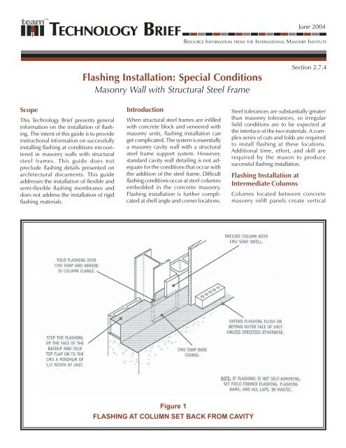
<strong>Flashing</strong> <strong>Installation</strong> at<br />
Intermediate Columns<br />
Columns located between concrete<br />
masonry infill panels create vertical<br />
Figure 1<br />
FLASHING AT COLUMN SET BACK FROM CAVITY
Figure 2<br />
FLASHING AT COLUMN SET INTO CAVITY<br />
from the wall cavity. The space in front<br />
of the column can be infilled with concrete<br />
masonry soaps. The flashing can<br />
be terminated within the CMU infill by<br />
cutting and folding its end over the CMU<br />
soap and adhering it against the column<br />
flange.<br />
Figure 2 illustrates flashing installation<br />
at a steel column that protrudes several<br />
inches into the wall cavity. Prefabbreaks<br />
in CMU coursing. Consequently,<br />
termination of the flashing into the CMU<br />
bed joint is disrupted at every column.<br />
Special cuts, folds and prefabrication are<br />
necessary to maintain flashing continuity.<br />
Column shape and proximity will dictate<br />
flashing installation methods.<br />
Figure 1 illustrates flashing installation<br />
at a steel column set back several inches<br />
ricated or field formed components are<br />
required to maintain flashing continuity.<br />
<strong>Flashing</strong> dams must be installed adjacent<br />
to the CMU where the column flange<br />
protrudes into the cavity. If the flashing<br />
dams are omitted, water that collects on<br />
the flashing will be diverted towards the<br />
column and possibly into the building.<br />
<strong>Flashing</strong> continuity can be maintained by<br />
cutting and folding a separate piece
Figure 3<br />
FLASHING AT COLUMN SET FLUSH WITH CAVITY<br />
of flashing and adhering it to the column<br />
and adjacent flashing membrane.<br />
Figure 3 illustrates flashing installation<br />
at a steel column with the column web<br />
positioned parallel to the wall cavity.<br />
Columns set in this manner create a void<br />
in the CMU backup, which makes flashing<br />
placement difficult. <strong>Masonry</strong> units<br />
should be set between the column<br />
flanges to create a profile that approximates<br />
that of the CMU infill. The flashing<br />
can be terminated by lapping it over<br />
the masonry units and adhering it to the<br />
web of the column. Prefabricated or field<br />
formed dams must be adhered to the<br />
flashing within the column to prevent<br />
water from flowing down the column<br />
flanges and into the building.<br />
<strong>Flashing</strong> <strong>Installation</strong> at<br />
Corner Columns<br />
<strong>Steel</strong> columns located at outer and inner<br />
corners create particularly difficult<br />
flashing conditions due to steel column<br />
shape and its increased exposure to the<br />
wall cavity. A complex series of cuts,<br />
folds and field fabrications are required<br />
to achieve successful flashing installation.
Figure 4<br />
OUTER CORNER FLASHING AT WALL BASE<br />
Figure 4 illustrates flashing installation<br />
of an outer corner column located at the<br />
wall base. The column web and flange<br />
are completely exposed to the wall<br />
cavity at the outer corner. This creates a<br />
flashing surface with multiple juts and<br />
returns. Several flashing dams must be<br />
provided to accommodate the irregularities.<br />
Attempting to extend, cut, and fold<br />
a continuous piece of flashing around<br />
the column can prove to be difficult.<br />
Field fabricating pieces of flashing and<br />
neatly wrapping them around the<br />
column surface likely will produce<br />
improved results.<br />
Figure 5 illustrates flashing installation<br />
of an outer corner column located at a<br />
shelf angle. <strong>Flashing</strong> installation at this<br />
location is unique because all surfaces of<br />
the column are exposed to the wall<br />
cavity. A complex series of cuts, folds and<br />
flashing fabrication are required to<br />
ensure flashing continuity. All flashing<br />
ends should be terminated by adhering<br />
them to steel surfaces. Attempting to<br />
extend the flashing into the CMU wythe<br />
above the steel beam is not practical and<br />
is difficult, if not impossible, to achieve.
Figure 5<br />
OUTER CORNER FLASHING AT SHELF ANGLE<br />
Figure 6 illustrates flashing installation<br />
of an inner corner column located at a<br />
shelf angle. <strong>Flashing</strong> inner column corners<br />
is not as complex as outer corners.<br />
<strong>Flashing</strong> continuity can be maintained<br />
by carefully cutting, folding and lapping<br />
the flashing ends. A flashing dam is<br />
required parallel to the column web to<br />
divert any collected water away from the<br />
column and back into the cavity.<br />
Conclusion<br />
<strong>Flashing</strong> masonry walls with structural<br />
steel frames can be tedious and requires<br />
additional time, effort, and skill by the<br />
mason. <strong>Installation</strong> may be compromised<br />
by the difference in construction tolerances<br />
as steel tolerances are often greater<br />
than those accepted in masonry. Field<br />
conditions often demand adjustments<br />
to be made to details shown on project<br />
drawings. The intent of this guide is to<br />
show solutions to common situations that<br />
occur. It is not to preclude other solutions<br />
put forth by the contractor or the<br />
architect.
Figure 6<br />
INNER CORNER FLASHING AT SHELF ANGLE<br />
This document is intended for the use of industry professionals who are competent to evaluate the significance and<br />
limitations of the information provided herein. This publication should not be used as the sole guide for masonry design and<br />
construction, and IMI disclaims any and all legal responsibility for the consequences of applying the information.<br />
© IMI 2004. All Rights Reserved.<br />
<strong>International</strong> <strong>Masonry</strong> <strong>Institute</strong> ■ 42 East Street ■ Annapolis, MD 21401 ■ 1-800-IMI-0988 ■ www.imiweb.org