FCD-E1A - RAD TÜRKİYE Data Communications
FCD-E1A - RAD TÜRKİYE Data Communications
FCD-E1A - RAD TÜRKİYE Data Communications

You also want an ePaper? Increase the reach of your titles
YUMPU automatically turns print PDFs into web optimized ePapers that Google loves.
<strong>FCD</strong>-<strong>E1A</strong><br />
E1 or Fractional E1 Access Unit<br />
FEATURES<br />
• Managed access for E1 and<br />
fractional E1 services<br />
• One or two data ports with<br />
selectable sync data rates:<br />
n × 56, n × 64 kbps<br />
• Optional sub-E1<br />
drop-and-insert user port for<br />
PBX connectivity<br />
• Failure-immune sub-E1 port<br />
ensuring uninterrupted<br />
service (G.703 only)<br />
• <strong>Data</strong> port interfaces: V.35,<br />
RS-530, V.36/RS-449, or<br />
X.21<br />
• Optional Ethernet or Fast<br />
Ethernet bridge, with or<br />
without VLAN support or IP<br />
router<br />
• Four ISDN BRI "S" interface<br />
user ports<br />
• Management:<br />
• Out-of-band via V.24<br />
supervisory port or<br />
Ethernet management<br />
port<br />
• Inband via TS0 or<br />
dedicated timeslot<br />
• Dial-in option for remote<br />
out-of-band management<br />
• Dial-out for alarm report<br />
• SNMP agent<br />
• Optional integrated ISDN<br />
backup<br />
• E1 interface complies with:<br />
ITU G.703, G.704, G.706,<br />
G.732, and G.823<br />
• Enhanced diagnostics<br />
include:<br />
• User-activated local and<br />
remote loopbacks<br />
• Integrated BER tester<br />
• Fractional E1 inband loop<br />
DESCRIPTION<br />
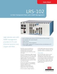
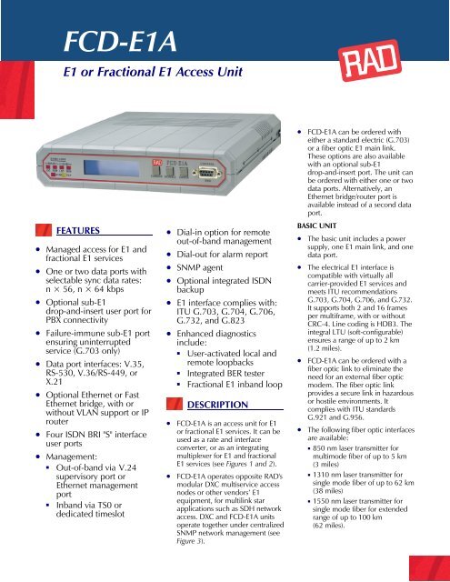
• <strong>FCD</strong>-<strong>E1A</strong> is an access unit for E1<br />
or fractional E1 services. It can be<br />
used as a rate and interface<br />
converter, or as an integrating<br />
multiplexer for E1 and fractional<br />
E1 services (see Figures 1 and 2).<br />
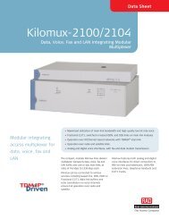
• <strong>FCD</strong>-<strong>E1A</strong> operates opposite <strong>RAD</strong>'s<br />
modular DXC multiservice access<br />
nodes or other vendors’ E1<br />
equipment, for multilink star<br />
applications such as SDH network<br />
access. DXC and <strong>FCD</strong>-<strong>E1A</strong> units<br />
operate together under centralized<br />
SNMP network management (see<br />
Figure 3).<br />
• <strong>FCD</strong>-<strong>E1A</strong> can be ordered with<br />
either a standard electric (G.703)<br />
or a fiber optic E1 main link.<br />
These options are also available<br />
with an optional sub-E1<br />
drop-and-insert port. The unit can<br />
be ordered with either one or two<br />
data ports. Alternatively, an<br />
Ethernet bridge/router port is<br />
available instead of a second data<br />
port.<br />
BASIC UNIT<br />
• The basic unit includes a power<br />
supply, one E1 main link, and one<br />
data port.<br />
• The electrical E1 interface is<br />
compatible with virtually all<br />
carrier-provided E1 services and<br />
meets ITU recommendations<br />
G.703, G.704, G.706, and G.732.<br />
It supports both 2 and 16 frames<br />
per multiframe, with or without<br />
CRC-4. Line coding is HDB3. The<br />
integral LTU (soft-configurable)<br />
ensures a range of up to 2 km<br />
(1.2 miles).<br />
• <strong>FCD</strong>-<strong>E1A</strong> can be ordered with a<br />
fiber optic link to eliminate the<br />
need for an external fiber optic<br />
modem. The fiber optic link<br />
provides a secure link in hazardous<br />
or hostile environments. It<br />
complies with ITU standards<br />
G.921 and G.956.<br />
• The following fiber optic interfaces<br />
are available:<br />
• 850 nm laser transmitter for<br />
multimode fiber of up to 5 km<br />
(3 miles)<br />
• 1310 nm laser transmitter for<br />
single mode fiber of up to 62 km<br />
(38 miles)<br />
• 1550 nm laser transmitter for<br />
single mode fiber for extended<br />
range of up to 100 km<br />
(62 miles).
<strong>FCD</strong>-<strong>E1A</strong><br />
E1 or Fractional E1 Access Unit<br />
• Timeslot assignment is<br />
programmable, allowing data from<br />
each data or sub-E1 port to be<br />
placed automatically into<br />
consecutive timeslots.<br />
Alternatively, the user can assign<br />
timeslots manually.<br />
• Multiple clock source selection<br />
ensures maximum flexibility for<br />
supporting different applications.<br />
The E1 main link may derive its<br />
timing from the recovered receive<br />
clock, from an internal oscillator,<br />
from one of the data ports, or<br />
from the sub-E1 port.<br />
• ISDN dial backup ensures the<br />
continuity of data services.<br />
• Bypassing the sub-E1 port to the<br />
G.703 main link (electric only)<br />
ensures uninterrupted service to<br />
the sub-E1 port and provides<br />
immunity from hardware or<br />
power failures.<br />
• <strong>FCD</strong>-<strong>E1A</strong> is a standalone unit. An<br />
optional rack mount adapter kit<br />
enables installation of one or two<br />
side-by-side units in a 19-inch<br />
rack (see Ordering).<br />
APPLICATIONS<br />
USER INTERFACES<br />
• The following interfaces can be<br />
ordered for the data port: V.35,<br />
RS-530, V.36/RS-449, or X.21.<br />
An optional second data port can<br />
be ordered with V.35, RS-530,<br />
V.24, V.36/RS-449, or X.21<br />
interfaces.<br />
• The synchronous data ports can<br />
operate in the following clock<br />
modes:<br />
• DCE: <strong>FCD</strong>-<strong>E1A</strong> provides both<br />
transmit and receive clocks to<br />
the user equipment, with<br />
optional sampling of the<br />
incoming data with an inverted<br />
clock.<br />
• DTE1: <strong>FCD</strong>-<strong>E1A</strong> provides the<br />
transmit clock. The connected<br />
user equipment provides receive<br />
clock (not for X.21).<br />
• DTE2: The connected user<br />
equipment provides both<br />
transmit and receive clocks (not<br />
for X.21).<br />
• When equipped with IR-ETH,<br />
IR-ETH/Q, or IR-ETH/QN<br />
interface modules, <strong>FCD</strong>-<strong>E1A</strong><br />
transparently connects remote<br />
LANs, as well as VLANs, over the<br />
E1 links. It filters Ethernet packets,<br />
forwarding only packets destined<br />
to the WAN.<br />
• The IR-ETH/QN port has a<br />
10/100BaseT interface that<br />
supports autonegotiation and<br />
VLAN frames.<br />
• <strong>FCD</strong>-<strong>E1A</strong> equipped with the IR-IP<br />
interface module operates as an IP<br />
gateway, forwarding packets<br />
destined to the IP network. This<br />
prevents broadcast to the WAN<br />
and enables the LAN users to<br />
register for an IP multicast group.<br />
• <strong>FCD</strong>-<strong>E1A</strong> with the IR-IP interface<br />
module connects the local IP<br />
networks to the public networks at<br />
full E1 speed, in contrast to<br />
connection over statistical<br />
protocols, such as Frame Relay.<br />
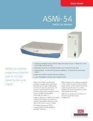
Figure 1. Extended Ethernet Management over E1 Network
• The IR-ETH/QN port is available<br />
with a 10/100BaseT interface. The<br />
other Ethernet port options are<br />
available only with a 10BaseT<br />
(UTP) interface.<br />
• The optional four ISDN "S"<br />
interfaces can extend ISDN<br />
services to locations that do not<br />
support ISDN. Each "S" interface<br />
port operates in full-duplex mode<br />
over a 4-wire twisted-pair at a<br />
range of up to 1000m (3300 ft).<br />
• The optional IBE backup interface<br />
can automatically back up the<br />
data port over switched ISDN<br />
networks.<br />
• The optional sub-E1 port can be<br />
configured to work without<br />
CRC-4, while the E1 main link is<br />
working with CRC-4. This allows<br />
non-CRC-4 E1 equipment to be<br />
connected over an E1 network<br />
that is using CRC-4.<br />
MANAGEMENT & MAINTENANCE<br />
• Status and diagnostic information<br />
is defined, configured, and<br />
monitored using one of the<br />
following methods:<br />
• Menu-driven management using<br />
the front panel LCD with three<br />
pushbuttons.<br />
• ASCII terminal connected to the<br />
SLIP control port<br />
• SNMP or Telnet management<br />
through either the SLIP control<br />
port or inband<br />
• The internal SNMP agent can be<br />
controlled by the <strong>RAD</strong>view SNMP<br />
network management application<br />
or any generic SNMP station.<br />
• <strong>FCD</strong>-<strong>E1A</strong> supports both dial-in<br />
and dial-out modem connections.<br />
These connections allow remote<br />
out-of-band configuration and<br />
monitoring, as well as sending<br />
callout alarm messages. Modems<br />
can be connected using the serial<br />
V.24 SLIP, PPP, or Ethernet ports.<br />
• Inband management uses the<br />
spare bits (S a bits) on timeslot 0<br />
(TS0) or a dedicated timeslot with<br />
standard protocols: Frame Relay<br />
(RFC 1490), PPP, and standard<br />
RIP2 routing. If spare bits on TS0<br />
are used for management access,<br />
they must be passed transparently<br />
end-to-end.<br />
• Maintenance capabilities include<br />
user-activated local and remote<br />
loopbacks on the E1 main link,<br />
sub-E1, and data ports. The user<br />
can activate a BER test for each<br />
data port individually.<br />
• Each data port responds to an<br />
ANSI FT1 inband loop code (RDL)<br />
generated by a remote <strong>FCD</strong>-<strong>E1A</strong><br />
or DXC in a specific bundle of<br />
timeslots allocated only to that<br />
port.<br />
• E1 network statistics are stored in<br />
memory according to RFC-1406<br />
and can be retrieved locally<br />
through the control port.<br />
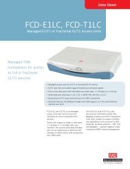
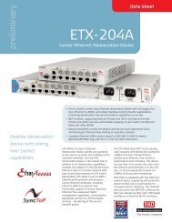
Figure 2. Co-connection of LAN and PBX Traffic to E1 Network
<strong>FCD</strong>-<strong>E1A</strong><br />
E1 or Fractional E1 Access Unit<br />
SPECIFICATIONS<br />
ELECTRIC E1 MAIN LINK<br />
(NETWORK) AND SUB-E1 PORTS<br />
• Framing<br />
256N (no MF, CCS)<br />
256N with CRC-4 (no MF, CCS)<br />
256S (TS16 MF, CAS)<br />
256S with CRC-4 (TS16 MF CAS)<br />
Unframed<br />
• Bit Rate<br />
2.048 Mbps<br />
• Line Code<br />
HDB3<br />
• Impedance<br />
120Ω, balanced<br />
75Ω, unbalanced<br />
• Signal Level<br />
Receive:<br />
0 to -36 dB with LTU<br />
0 to -10 dB without LTU<br />
Transmit:<br />
±3V (±10%), balanced<br />
±2.37V (±10%), unbalanced<br />
• Jitter Performance<br />
As per ITU G.823,<br />
ETSI TBR-12, TBR-13<br />
• Connectors<br />
RJ-45, 8-pin, balanced<br />
Two BNC coaxial, unbalanced<br />
• Transmit Timing<br />
Locked to the system clock<br />
• Compliance<br />
ITU G.703, G.704, G.706, G.732<br />
• Performance Monitoring<br />
(Main Link only)<br />
Local support of CRC-4<br />
Statistics according to RFC-1406<br />
FIBER OPTIC MAIN LINK<br />
• Compliance<br />
G.921, G.956<br />
• Transmitter Type<br />
Laser<br />
• Fiber Optic Characteristics<br />
See Table 1<br />
• Connectors<br />
ST, FC/PC, or SC (see Ordering)<br />
DATA PORTS<br />
• Number of <strong>Data</strong> Ports<br />
One or two (see Ordering)<br />
• Interfaces<br />
• V.35, RS-530, V.36, X.21<br />
• V.24 (data port 2 only)<br />
• Connectors<br />
D-type 25-pin RS-530, female<br />
• <strong>Data</strong> Rate<br />
n × 56 or n × 64 kbps,<br />
(n=1 to 31)<br />
• Clock Modes<br />
DCE: Rx and Tx clock to DTE<br />
DTE1: Rx clock to user device,<br />
Tx clock from user device<br />
DTE2: Rx and Tx clock from DCE<br />
• Control Signals<br />
• CTS follows RTS or constantly<br />
ON, soft-selectable<br />
• DSR constantly ON, unless in<br />
test mode<br />
• DCD constantly ON, unless in<br />
SYNC LOSS<br />
ETHERNET BRIDGE/ROUTER PORT<br />
• Characteristics<br />
See Table 2<br />
• Connector<br />
Shielded RJ-45<br />
"S" INTERFACE PORTS<br />
• Number of Ports<br />
Four "S" 2B+D interface channels<br />
• Compliance<br />
ETS 300012<br />
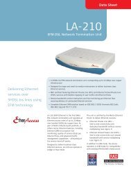
Figure 3. SDH Access Solution for Multiple Remote Sites
<strong>FCD</strong>-<strong>E1A</strong><br />
E1 or Fractional E1 Access Unit<br />
• Interface<br />
4-wire, full-duplex<br />
• Bit Rate<br />
192 kbps ±100 ppm<br />
• Line Code<br />
Pseudoternary<br />
• Line Termination<br />
100Ω ±5%<br />
• Range<br />
1000m (3300 ft)<br />
• Signal Levels<br />
Receive:<br />
+1.5 to -7.5 dB relative to the<br />
nominal amplitude<br />
Transmit:<br />
±750 mV<br />
• Timing Modes<br />
NT: Transmit timing is locked to<br />
system timing clock<br />
TE: Looped back towards the "S"<br />
interface (timing is derived<br />
from Rx signal from the ISDN<br />
switch NT)<br />
• Connector<br />
RJ-45 (8-pin) per channel<br />
• Power Feeding Voltage<br />
38V (±4V), as per TR5805-3074<br />
1W per channel<br />
IBE BACKUP INTERFACE<br />
• Number of Channels<br />
One BRI “S” channel<br />
• Standards<br />
ITU I.430, Q.921, Q.931,<br />
ETSI NET 3, i-CTR3<br />
• Signal Format<br />
Pseudoternary line coding<br />
• Line Type<br />
2 unloaded twisted-pair cables<br />
• Impedance<br />
100Ω, balanced<br />
• Range<br />
Up to 1000m (3300 ft)<br />
• Connector<br />
RJ-45 (8-pin)<br />
MANAGEMENT PORTS<br />
• CONTROL DCE Port<br />
• Interface and connector:<br />
V.24/RS-232, 9-pin D-type,<br />
female<br />
• Format: Asynchronous<br />
• Baud rate: 1.2–19.2 kbps,<br />
autobaud<br />
• Character: 8 bit no parity, 7 bit<br />
odd, or even parity<br />
• CONTROL Port (Serial)<br />
• Connector: V.24/RS-232, 9-pin<br />
D-type, female<br />
• Format: Asynchronous<br />
• Baud rate: 0.3–57.6 kbps,<br />
autobaud<br />
• Character: 8 bit no parity, 7 bit<br />
odd or even parity<br />
• CONTROL Port (Ethernet)<br />
Ethernet 10BaseT, RJ-45<br />
GENERAL<br />
• System Clock<br />
• Internal clock: ±30 ppm<br />
• Loopback timing (sub, main E1):<br />
±130 ppm<br />
• External timing from data port:<br />
n × 56, n × 64 kbps ±130 ppm<br />
• Diagnostics<br />
Main E1 link:<br />
Local and remote loopback<br />
Sub-E1 port:<br />
• Local and remote loopback<br />
• BER test<br />
<strong>Data</strong> port:<br />
• Local and remote loopback<br />
• BER test<br />
• Inband code activated loopback<br />
per data port<br />
• Timeslot Allocation<br />
• Consecutive (bundled)<br />
• User-defined<br />
• Front Panel Control<br />
LCD: 2 rows of 16 characters<br />
Push buttons: Cursor, Scroll, Enter<br />
• Indicators<br />
General: TST, ALM<br />
Main E1: LOC SYNC LOSS, REM<br />
SYNC LOSS<br />
Sub-E1: LOC SYNC LOSS, REM<br />
SYNC LOSS<br />
All indicators are red except TST<br />
(yellow).<br />
• Alarms<br />
Last 100 alarms are stored and<br />
available for retrieval. Each alarm<br />
is time-stamped.<br />
• Alarm Relay<br />
3 relay contacts are available on<br />
the alarm relay port.<br />
Activated by alarms in the<br />
user-defined alarm buffer.<br />
Operating<br />
Wavelength<br />
[nm]<br />
Fiber Type<br />
[µm]<br />
Table 1. Fiber Optic Interface Characteristics<br />
Typical<br />
Output Power<br />
[dBm]<br />
Receiver<br />
Sensitivity<br />
[dBm]<br />
Typical Optical<br />
Budget<br />
[dB]<br />
Typical Maximum<br />
Range<br />
[km] [mi]<br />
850 62.5/125 multimode -16 -38 20 5 3<br />
1310 9/125 single mode -12 -40 28 62 38<br />
1550 9/125 single mode -12 -40 28 100 60
<strong>FCD</strong>-<strong>E1A</strong><br />
E1 or Fractional E1 Access Unit<br />
• Physical<br />
Height: 4.3 cm (1.7 in) (1U)<br />
Width: 21.5 cm (8.5 in)<br />
Depth: 24.3 cm (9.5 in)<br />
Weight: 1.3 kg (2.9 lb)<br />
• Power<br />
AC: 100 to 240 VAC; 47 to 63 Hz<br />
DC: -48 VDC (40 to 57 VDC)<br />
• Power consumption<br />
10W max<br />
• Environment<br />
Temperature: 0°–50°C (32°–122°F)<br />
Humidity: up to 90%,<br />
non-condensing<br />
ORDERING<br />
<strong>FCD</strong>-<strong>E1A</strong>/*/~/$/&/%/#+<br />
E1 or fractional E1 access unit<br />
* Specify S1 for optional<br />
drop & insert sub-E1 port.<br />
(Default is without sub-E1 port)<br />
~ Specify power supply type:<br />
AC for 110 VAC to 240 VAC<br />
48 for -48 VDC<br />
$ Specify management port<br />
interface:<br />
V24 for V.24/RS232 (DB-9)<br />
UTP for Ethernet 10BaseT (UTP)<br />
& Specify data port interface:<br />
530 for RS-530 interface<br />
V35 for V.35 interface<br />
X21 for X.21 interface<br />
449 for V.36/RS-449 interface<br />
% Specify optional second data port<br />
interface:<br />
530 for RS-530 interface<br />
V24 for V.24 interface<br />
V35 for V.35 interface<br />
X21 for X.21 interface<br />
449 for V.36/RS-449 interface<br />
ETUB for IR-ETH UTP Ethernet<br />
bridge (10BaseT)<br />
ETUQ for IR-ETH/Q UTP Ethernet<br />
bridge VLAN (10BaseT)<br />
ETQN for IR-ETH/QN UTP<br />
Ethernet bridge VLAN<br />
(10/100BaseT)<br />
ETUR for IR-IP UTP Ethernet router<br />
(10BaseT)<br />
S0 for 4×S0 ISDN<br />
IBE for ISDN backup “S” interface<br />
# Specify link connector type:<br />
ST for ST type fiber connectors<br />
FC for FC/PC type fiber connectors<br />
SC for SC type fiber connectors<br />
(Default is G.703 electrical/copper<br />
interface)<br />
+ Specify optical interface wavelength<br />
and transmitter type (not relevant for<br />
copper interface):<br />
85 for 850 nm, multimode, laser<br />
13L for 1310 nm, single mode, laser<br />
15L for 1550 nm, single mode, laser<br />
SUPPLIED ACCESSORIES<br />
AC power cord (when AC power<br />
supply is ordered)<br />
DC adapter plug (when DC power<br />
supply is ordered)<br />
The following cables (suitable for use in<br />
DCE clock mode only) are supplied for<br />
each data port interface specified. Cable<br />
length is 2m (6 ft):<br />
CBL-HS2/V/1 for 34-pin V.35, DCE<br />
CBL-HS2/R/1 for 37-pin V.36, DCE<br />
CBL-HS2/X/1 for 15-pin X.21, DCE<br />
OPTIONAL ACCESSORIES<br />
RM-17<br />
Hardware kit for mounting one or two<br />
units side-by-side in a 19-inch rack<br />
CBL-HS2/*/#<br />
Adapter cables for DB-25 channel<br />
connectors<br />
* Specify interface, clock mode:<br />
V/2 for 34-pin V.35, DTE1<br />
V/3 for 34-pin V.35, DTE2<br />
R/2 for 37-pin V.36/RS-449, DTE1<br />
R/3 for 37-pin V.36/RS-449, DTE2<br />
# Specify cable connector type:<br />
F for female<br />
M for male<br />
Interface<br />
Module<br />
LAN Table<br />
[addresses]<br />
Table 2. Ethernet Interface Modules Characteristics<br />
Filtering and<br />
Forwarding<br />
[frames/second]<br />
Buffer<br />
[frames]<br />
Line Code<br />
IR-ETH 10,000 15,000 256 Manchester HDLC<br />
IR-ETH/Q 2,000 2,000 256 Manchester HDLC<br />
IR-ETH/QN 1,000 150,000 85 • 10BaseT: Manchester HDLC<br />
• 100BaseT: MLT3<br />
IR-IP<br />
IP Addresses<br />
256<br />
Filtering 35,000<br />
Forwarding 30,000<br />
WAN Protocol<br />
256 Manchester • PPP (PAP/CHAP)<br />
• Frame Relay (RFC 1490)<br />
• HDLC<br />
Note: All the Ethernet interface modules conform to the IEEE 802.3/Ethernet V2 standard. Additionally, IR-ETH/Q<br />
supports IEEE 802.1/q frames, and IR-ETH/QN conforms to IEEE 802.1Q (relevant parts), 802.1p and 802.3x.<br />
www.rad.com<br />
International Headquarters<br />
24 Raoul Wallenberg Street<br />
Tel Aviv 69719, Israel<br />
Tel: 972-3-6458181<br />
Fax: 972-3-6498250<br />
Email: market@rad.com<br />
North America Headquarters<br />
900 Corporate Drive<br />
Mahwah, NJ 07430, USA<br />
Tel: (201) 529-1100<br />
Toll free: 1-800 444-7234<br />
Fax: (201) 529-5777<br />
Email: market@radusa.com<br />
201-100-01/06<br />
© 1991–2006 <strong>RAD</strong> <strong>Data</strong> <strong>Communications</strong> Ltd. Specifications are subject to change without prior notice.<br />
All other trademarks are the property of their respective holders.