FCD-E1LC, FCD-T1LC
FCD-E1LC, FCD-T1LC
FCD-E1LC, FCD-T1LC

You also want an ePaper? Increase the reach of your titles
YUMPU automatically turns print PDFs into web optimized ePapers that Google loves.
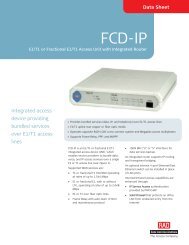
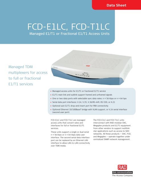
Data Sheet<strong>FCD</strong>-<strong>E1LC</strong>, <strong>FCD</strong>-<strong>T1LC</strong>Managed E1/T1 or Fractional E1/T1 Access UnitsManaged TDMmultiplexers for accessto full or fractionalE1/T1 services• Managed access units for E1/T1 or fractional E1/T1 service• E1/T1 main link and sublink support framed and unframed signals• One or two data ports with selectable sync data rates: n × 56 kbps or n × 64 bps• Serial data port interfaces: V.24, V.35, V.36/RS-449, RS-530, or X.21• Optional sub-E1/T1 drop-and-insert port for PBX connectivity• Optional Ethernet 10/100BaseT bridge with VLAN support, or V.24 serial interface(second user port)<strong>FCD</strong>-<strong>E1LC</strong> and <strong>FCD</strong>-<strong>T1LC</strong> are managedaccess units that convert rates andinterfaces for full or fractional E1/T1services.These units support a single or dual serialn × 56 kbps or n × 64 kbps data userinterface. The second serial data interfaceport can be replaced by an Ethernet LANinterface to allow LAN-to-LAN connectivityover TDM media.The <strong>FCD</strong>-<strong>E1LC</strong> and <strong>FCD</strong>-<strong>T1LC</strong> unitsinterconnect with RAD modular DXC,Megaplex products and E1/T1 equipmentfrom other vendors to support multilinkstar applications such as access to SDHnetworks. All these products — DXC, <strong>FCD</strong>,and Megaplex — operate together undercentralized SNMP network management.The Access Company
<strong>FCD</strong>-<strong>E1LC</strong>, <strong>FCD</strong>-<strong>T1LC</strong>Managed E1/T1 or Fractional E1/T1 Access UnitsThe E1 interface is compatible withvirtually all carrier-provided E1 servicesand meets ITU recommendations G.703,G.704, G.706, G.732, G.823, and G.826.It supports both 2 and 16 frames permultiframe, with or without CRC-4.The E1 interface also accepts a 2048 kbpsdata stream and converts it to an ITU-TRec. G.703 unframed signal for transportover the E1 main link and sublink. Linecode is HDB3. The integral LTU ensures arange of up to 2 km (1.2 miles) and issoftware-selectable.The T1 interface is compatible withvirtually all carrier-provided T1 services,including ASDS from AT&T. It complieswith TR-62411 and TR-62421 andsupports D4 and ESF framing formats.Zero suppression over the line issoftware-selectable for either transparent,B7ZS or B8ZS. The software-selectableintegral CSU ensures a range of up to2.1 km (1.3 miles).The optional sub-E1 port can beconfigured to work without CRC-4, whilethe E1 main link is working with CRC-4.This enables connection of E1 equipmentnot supporting CRC-4, over an E1 networkthat is working with CRC-4.The optional sub-T1 port can beconfigured with D4 or ESF framing, whilethe T1 main link framing is ESF. Thisenables connection of T1 D4 equipmentover an ESF T1 network.The <strong>FCD</strong>-<strong>E1LC</strong> and <strong>FCD</strong>-<strong>T1LC</strong> units can beprogrammed to assign data automaticallyfrom each data port into consecutivetimeslots. The user can also assigntimeslots manually.Timing for the E1/T1 main link and sublinkmay come from the recovered receiveclock, an internal oscillator, or one of thedata ports. This multiple clock sourceselection ensures maximum flexibility forsupporting different applications.Front panel LEDs indicate alarms, E1/T1signal loss, and diagnostic loopbackoperation. Rear panel LEDs on theEthernet interface modules indicate LANstatus and activity.<strong>FCD</strong>-<strong>E1LC</strong> and <strong>FCD</strong>-<strong>T1LC</strong> are compactstandalone units. A rack mount adapter kitenables installation of one or two (sideby-side)units in a 19-inch rack.USER INTERFACESThe <strong>FCD</strong>-<strong>E1LC</strong> and <strong>FCD</strong>-<strong>T1LC</strong> units featurethe following user interfaces:• Serial data interfaces: V.24, V.35,V.36/RS-449, RS-530, X.21• Ethernet 10/100BaseT LAN interfacemodule with a built-in bridge(IR-ETH/QN).The synchronous data ports of <strong>FCD</strong>-<strong>E1LC</strong>operate in the following clock modes:• DCE: The <strong>FCD</strong> units provide bothtransmit and receive clocks to the userequipment, with optional sampling ofthe incoming data with an invertedclock• DTE1: The <strong>FCD</strong> units provide thetransmit clock, while the transmit clockis provided by the attached userequipment• DTE2: The attached user equipmentprovides both transmit and receiveclocks.The IR-ETH/QN interface module has a10/100BaseT interface that supports VLANframes, autonegotiation, faultpropagation, and automatic learning andaging. The module transparently connects<strong>FCD</strong>-<strong>E1LC</strong> and <strong>FCD</strong>-<strong>T1LC</strong> to remote LANsover E1/T1 links. It filters Ethernet framesand forwards only frames that aredestined for the WAN.
MANAGEMENT & MAINTENANCEStatus and diagnostic information isdefined, configured, and monitored usingone of the following methods:• ASCII terminal connected to the asynccontrol port• SNMP management• Telnet.All models support an internal SNMP agentthat is managed by any generic SNMPstation or by the RADview SNMP-basedmanagement application.<strong>FCD</strong>-<strong>E1LC</strong> and <strong>FCD</strong>-<strong>T1LC</strong> support bothdial-in and dial-out modem connectionsthrough the serial RS-232 port, by usingSLIP or PPP protocol or a command lineinterpreter on an ASCII terminal. Theseout-of-band connections can be used forremote configuration and monitoring, aswell as for sending callout alarmmessages.Up to 100 time-stamped alarms areavailable for retrieval through thesupervision terminal, a Telnet host, or aRADview management station.Inband management can be performedeither by dedicated timeslot usingstandard Frame Relay protocol(RFC 1490), or by using the spare S a bitson timeslot 0 for <strong>FCD</strong>-<strong>E1LC</strong> or FDL bits for<strong>FCD</strong>-<strong>T1LC</strong>. This allows the user to setup,monitor, and run diagnostics on theremote unit. The spare bits on TS0 or FDLthat are used for inband access must bepassed transparently end-to-end.Maintenance capabilities includeuser-activated local and remote loopbackson the E1/T1 main link, sublink, and dataports. The user can activate a BER test onthe main link. Also, the main link respondsto an ANSI FT1 RDL (T1.403) inband loopcode, or a user-configured patterngenerated by a remote <strong>FCD</strong>-<strong>E1LC</strong>,<strong>FCD</strong>-<strong>T1LC</strong>, or DXC in a specific bundle oftimeslots allocated only to that port. Theuser can also define BER or inband teststo run on any timeslot of the main link.E1 network statistics are stored inmemory, according to RFC 1406.Statistical information can be retrievedlocally through the control port.T1 network statistics are stored inmemory, according to ANSI and AT&Tstandards. The statistical information maybe retrieved by the service provider (ANSIonly) or locally through the control port.Figure 1. Extended Ethernet Management over E1/T1 Network
Data SheetSpecificationsE1 MAIN LINK AND SUBLINKFraming256N (no MF, CCS)256N (no MF, CCS) with CRC-4256S (TS16 MF, CAS)256S (TS16 MF, CAS) with CRC-4UnframedBit Rate2.048 MbpsLine CodeAMIZero SuppressionHDB3Line Impedance120Ω, balanced75Ω, unbalancedTransmit TimingLocked to the system clockSignal LevelReceive:0 to –10 dB without LTU0 to –36 dB with LTUTransmit:±3V (±10%), balanced±2.37V (±10%), unbalancedJitter PerformanceAs per ITU G.823, ETSI TBR-12 and TBR-13ConnectorsRJ-45, 8-pin, balancedTwo BNC coaxial, unbalanced, usingadapter cableComplianceITU G.703, G.704, G.706, G.732, G.823,G.826Performance MonitoringLocal support of CRC-4Full statistical diagnostics according toRFC-1406T1 MAIN LINK AND SUBLINKFramingD4ESFUnframed (main link only)Bit Rate1.544 MbpsLine CodeAMIZero SuppressionTransparent, B7ZS, B8ZSLine Impedance100Ω, balancedTransmit TimingLocked to the system clockSignal LevelReceive:0 to –10 dB without CSU0 to –36 dB with CSUTransmit:–7.5, –15, –22.5 dB with CSU±3V, ±10% soft adjustable at 0 to 655ft without CSUT1 Jitter PerformanceAs per AT&T TR-62411ConnectorRJ-45, 8-pin, balancedComplianceAT&T TR-62411, AT&T 54016, AT&TTR-62421, ANSI T1.403Performance MonitoringLocal support of ESF diagnostics accordingto AT&T PUB 54016Full statistical diagnostics according toANSI T1.403-198DATA PORTSConnectorsD-type, 25-pin, RS-530, female(converted via adapter cables to V.35,X.21, V.36/RS-449)Additional connectors for second userport: D-type, 25-pin, female for V.24,RJ-45 for ETHData Raten × 56/64 kbps (n=1 to 24) for T1n × 64 kbps (n=1 to 31) for E1n × 64 kbps (n=1 to 2) for V.24 portClock ModesDCE: Rx and Tx clock to user deviceDTE1: Rx clock to user device;Tx clock from user device (not for X.21and V.24)DTE2: Rx and Tx clock from user device(not for X.21 and V.24)Control SignalsCTS follows RTS or constantly ON, softselectableDSR constantly ON, unless in test modeDCD constantly ON, unless in sync loss
<strong>FCD</strong>-<strong>E1LC</strong>, <strong>FCD</strong>-<strong>T1LC</strong>Managed E1/T1 or Fractional E1/T1 Access UnitsETHERNET BRIDGE PORTInterface and Connector10/100BaseT (UTP) with shielded RJ-45Maximum Frame Length1536 bytesLAN Table2048 MAC addressesThroughput4,000 ppsLatency300 μsec (64-byte frame size, 2M LAN rate)Buffer120 framesLine Code10BaseT: Manchester100BaseT: MLT3WAN ProtocolHDLCDIAGNOSTICSMain E1/T1 linkLocal loopbackRemote loopbackBER testCode-activated inband loopback per dataportCode-activated T1 network loopback(<strong>FCD</strong>-<strong>T1LC</strong> only)SublinkLocal loopbackRemote loopbackCode-activated T1 network loopback(<strong>FCD</strong>-<strong>T1LC</strong> only)Data PortLocal loopbackRemote loopbackGENERALSystem ClockInternal clock: ±50 ppmLoopback timing: ±130 ppmExternal timing from data port: ±130 ppmManagement PortInterface: RS-232, 9-pin D-type, femaleFormat: asynchronousBaud rate: 1.2–115.2 kbps, autobaudCharacter: 8-bit no parity, 7-bit odd oreven parityTimeslot AllocationConsecutive (bundled)User-definedIndicatorsGeneral: PWR (green), TST (yellow), ALM(red)Main/sub-E1: LOC SYNC LOSS (red), REMSYNC LOSS (red)Main/sub-T1: RED ALARM (red), YELALARM (yellow)PhysicalHeight: 4.4 cm (1.7 in)Width: 21.7 cm (8.5 in)Depth: 17.0 cm (6.7 in)Weight: 0.8 kg (1.8 lb)PowerAC/DC: 100 to 240 VAC, –48 to –60 VDC,nominalPower consumption: 5W max.EnvironmentTemperature: 0°–50°C (32°–122°F)Humidity: Up to 90%, non–condensingTable 2. <strong>FCD</strong> Comparison TableFeatures <strong>FCD</strong>-E1/T1 <strong>FCD</strong>-E1L/T1L <strong>FCD</strong>-<strong>E1LC</strong>/<strong>T1LC</strong>Total user ports 3 2 3Interface typesRS-530, V.35, V.36, X.21,Ethernet bridge (10BaseT withVLAN support), Sub-E1RS-530, V.35, V.36, X.21,Ethernet bridge (10/100BaseTwith VLAN support), ETH routerRS-530, V.24, V.35, V.36, X.21,Ethernet Bridge (10/100BaseTwith VLAN support), Sub-E1E1/T1 line type Copper/Fiber Copper CopperLCD panel – –Auto-configuration – –SNMP management Interoperability Megaplex, DXC Megaplex, DXC Megaplex, DXC
<strong>FCD</strong>-<strong>E1LC</strong>, <strong>FCD</strong>-<strong>T1LC</strong>Managed E1/T1 or Fractional E1/T1 Access UnitsData SheetOrdering<strong>FCD</strong>-<strong>E1LC</strong>/&/*/%E1 or fractional E1 access unit<strong>FCD</strong>-<strong>T1LC</strong>/&/*/%T1 or fractional T1 access unitLegend& Data port interface:530 RS-530V35 V.35X21 X.21V36 V.36/RS-449* S Optional drop-and-insert E1/T1sublink% Optional second data port interface:530 RS-530V35 V.35X21 X.21V36 V.36/RS-449V24 for V.24ETQN 10/100BaseT Ethernet bridgewith VLAN supportSUPPLIED ACCESSORIESPower cord and AC/DC adaptor plugThe following cables are supplied for eachdata port interface specified for operatingin DCE clock mode:CBL-HS2/V/1 for 34-pin V.35CBL-HS2/R/1 for 37-pin V.36/RS-449CBL-HS2/X/1 for 15-pin X.21OPTIONAL ACCESSORIESRM-33-2Hardware for mounting one or two unitsin a 19-inch rackCBL-DB9F-DB9M-STRControl port cableCBL-RJ45/2BNC/E1/XRJ-45 to BNC adaptor cable(for unbalanced main link interface)CBL-RJ45/2BNC/E1RJ-45 to BNC adaptor cable(for unbalanced sublink interface)CBL-HS2/*/#Adaptor cables for DB-25 channelconnectors, for operation in the DTE1and DTE2 clock modesLegend* Interface, clock mode:V/2 34-pin V.35, DTE1V/3 34-pin V.35, DTE2R/2 37-pin V.36/RS-449, DTE1R/3 37-pin V.36/RS-449, DTE2# Cable connector typeF femaleM male389-100-12/07 Specifications are subject to change without prior notice. © 1988–2007 RAD Data Communications Ltd. All other trademarks are the property of their respective holders.International Headquarters24 Raoul Wallenberg StreetTel Aviv 69719, IsraelTel. 972-3-6458181Fax 972-3-6498250, 6474436E-mail market@rad.comwww.rad.comNorth America Headquarters900 Corporate DriveMahwah, NJ 07430, USATel. 201-5291100Toll free 1-800-4447234Fax 201-5295777E-mail market@radusa.comThe Access Company