Fuel Tank Fill Station - Earthsafe Systems, Inc.
Fuel Tank Fill Station - Earthsafe Systems, Inc.
Fuel Tank Fill Station - Earthsafe Systems, Inc.

Create successful ePaper yourself
Turn your PDF publications into a flip-book with our unique Google optimized e-Paper software.
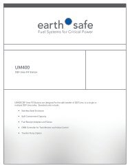
INSTALLATION, OPERATION, AND MAINTENANCE MANUAL<br />
Model M400<br />
<strong>Fuel</strong> <strong>Tank</strong> <strong>Fill</strong> <strong>Station</strong><br />
<strong>Earthsafe</strong> <strong>Systems</strong>, <strong>Inc</strong>.<br />
7553 S. Madison<br />
Willowbrook, IL 60527<br />
T: (630) 794-5100<br />
F: (630) 794-5106<br />
info@earthsafe.com<br />
www.earthsafe.com<br />
Updated: October 1, 2009<br />
The information contained herein is proprietary and is provided for the sole purpose of the owner’s installation,<br />
operation, and maintenance of the system. Reproduction of this information for other purposes is prohibited<br />
without the prior consent of <strong>Earthsafe</strong> <strong>Systems</strong>, <strong>Inc</strong>.
Model C800<br />
<strong>Fuel</strong> <strong>Tank</strong> <strong>Fill</strong> <strong>Station</strong><br />
INSTALLATION, OPERATION, AND MAINTENANCE<br />
EMERGENCY POWER FUEL SYSTEMS<br />
2 of 13<br />
Notice<br />
<strong>Earthsafe</strong> makes no warranty of any kind with regard to this publication, including but not<br />
limited to, the implied warranties of merchantability and fitness for a particular purpose.<br />
<strong>Earthsafe</strong> shall not be liable for errors contained herein or for incidental or consequential<br />
damages in connection with the furnishing, performance or use of this publication. <strong>Earthsafe</strong><br />
reserves the right to change system options or features, or the information contained in this<br />
publication. This publication contains proprietary information which is protected by<br />
copyright. All rights reserved. No part of this publication may by photocopied, reproduced,<br />
or translated to another language without the prior written consent of <strong>Earthsafe</strong>.<br />
Damage Claims<br />
Thoroughly examine all components and units as soon as they are received. If damaged,<br />
write a complete and detailed description of the damage on the face of the freight bill.<br />
The carriers agent must verify the inspection and sign the description. Immediately notify<br />
the delivering carrier of damage or loss. This notification may be given either in person or<br />
by telephone. Written confirmation must be mailed within 48 hours. Risk of loss, or damage<br />
to merchandise belongs with the buyer. It is the buyers responsibility to file a claim with the<br />
carrier involved. Immediately advise <strong>Earthsafe</strong> of the problem so that we may assist you.<br />
Safety Information<br />
UL Listed. The <strong>Earthsafe</strong> CentraPlex Control Module is UL listed.<br />
Intended Use. The <strong>Earthsafe</strong> CentraPlex Control Module is intended for use with diesel fuel<br />
systems for emergency power generators. The control module and any connected sensors or<br />
devices are intended for operation only within ordinary electrical areas. Use of the module<br />
and connected sensors or devices within hazardous electrical areas is prohibited.<br />
Intellectual Property<br />
The equipment and software described herein are the property of <strong>Earthsafe</strong> <strong>Systems</strong>, <strong>Inc</strong>.<br />
and are protected by various trademarks and patents.
Model C800<br />
<strong>Fuel</strong> <strong>Tank</strong> <strong>Fill</strong> <strong>Station</strong><br />
INSTALLATION, OPERATION, AND MAINTENANCE<br />
EMERGENCY POWER FUEL SYSTEMS<br />
3 of 13<br />
Table of Contents<br />
Safety Information . . . . . . . . . . . . . . . . . . . . . . . . . . . .4<br />
General Description . . . . . . . . . . . . . . . . . . . . . . . . .5<br />
Planning the Installation . . . . . . . . . . . . . . . . . . . . . . .7<br />
Installation . . . . . . . . . . . . . . . . . . . . . . . . . . . . . . . . .8<br />
Startup . . . . . . . . . . . . . . . . . . . . . . . . . . . . . . . . . . . . .9<br />
Testing . . . . . . . . . . . . . . . . . . . . . . . . . . . . . . . . . . . .10<br />
Operation . . . . . . . . . . . . . . . . . . . . . . . . . . . . . . . . .11<br />
Maintenance . . . . . . . . . . . . . . . . . . . . . . . . . . . . . . .12<br />
Troubleshooting . . . . . . . . . . . . . . . . . . . . . . . . . . . .12<br />
Spare Parts . . . . . . . . . . . . . . . . . . . . . . . . . . . . . . . . .12<br />
Warranty and Service . . . . . . . . . . . . . . . . . . . . . . . .13
Model C800<br />
<strong>Fuel</strong> <strong>Tank</strong> <strong>Fill</strong> <strong>Station</strong><br />
INSTALLATION, OPERATION, AND MAINTENANCE<br />
EMERGENCY POWER FUEL SYSTEMS<br />
4 of 13<br />
Safety notices – General Safety Rules – Symbols (danger-warning-caution)<br />
SAFETY INFORMATION AND INSTRUCTIONS<br />
Danger — Failure to follow the indicated instruction may result in serious injury or death.<br />
Warning — In addition to possible serious injury or death, failure to follow the indicated<br />
instruction may cause damage to pump and/or other equipment.<br />
IMPROPER INSTALLATION, OPERATION OR MAINTENANCE MAY CAUSE SERIOUS INJURY<br />
OR DEATH AND/OR RESULT IN DAMAGE TO UNIT AND/OR OTHER EQUIPMENT.<br />
EARTHSAFE’S WARRANTY DOES NOT COVER FAILURE DUE TO IMPROPER INSTALLATION,<br />
OPERATION OR MAINTENANCE.<br />
THIS INFORMATION MUST BE FULLY READ BEFORE BEGINNING INSTALLATION,<br />
OPERATION OR MAINTENANCE OF EQUIPMENT AND MUST BE KEPT WITH EQUIPMENT.<br />
EQUIPMENT MUST BE INSTALLED, OPERATED AND MAINTAINED ONLY BY SUITABLY<br />
TRAINED AND QUALIFIED PERSONS.<br />
THE FOLLOWING SAFETY INSTRUCTIONS MUST BE FOLLOWED AND ADHERED TO<br />
AT ALL TIMES.<br />
Symbol Legend:<br />
Danger — Failure to follow the indicated instruction may result in serious injury or death<br />
Warning — In addition to possible serious injury or death, failure to follow the indicated<br />
instruction may cause damage to pump and/or other equipment.<br />
BEFORE opening any pipe system, pump, or valve be sure that:<br />
• Any pressure in the chamber has been completely vented through the suction or<br />
discharge lines or other appropriate openings or connections.<br />
• The electrical system system means has been “locked out” or otherwise been made<br />
non-operational so that it cannot be started while work is being done on the equipment.<br />
• You have obtained appropriate material safety data sheet (MSDS) and understand and<br />
follow all precautions appropriate for the safe handling of the material.<br />
INSTALL pressure gauges/sensors at piping and pump connections to the equipment to<br />
monitor pressures.<br />
USE extreme caution when lifting the pump. Suitable lifting devices should be used when<br />
appropriate.<br />
THE equipment must be installed in a matter that allows safe access for routine maintenance and<br />
for inspection during operation to check for leakage and monitor operation.
Model C800<br />
<strong>Fuel</strong> <strong>Tank</strong> <strong>Fill</strong> <strong>Station</strong><br />
INSTALLATION, OPERATION, AND MAINTENANCE<br />
EMERGENCY POWER FUEL SYSTEMS<br />
5 of 13<br />
General Description<br />
<strong>Fill</strong> System for <strong>Tank</strong>s in Buildings.<br />
The <strong>Earthsafe</strong> M400 Compact <strong>Fill</strong> <strong>Station</strong> is designed for the safe filling of fuel tanks located inside<br />
buildings. The system is designed to install outside the building to accept fuel from delivery trucks<br />
and safely transfer fuel to the fuel tank in the building.<br />
Overfill Prevention Safety.<br />
The system is designed with overfill prevention safety. The electronic controller at the fill station<br />
monitors the fuel level in the tank as a continuous level reading (0-100%) or as a set of high level<br />
sensors (85-90-95%). The controller provides audible and visual high level warning at 85%, high<br />
level alarm at 90%, and critical high level at 95%. The controller monitors the position of actuated<br />
fill pipe valves, and closes the valve upon high level.<br />
Single or Multi-<strong>Tank</strong> <strong>Systems</strong>.<br />
The <strong>Earthsafe</strong> Compact <strong>Fill</strong> <strong>Station</strong> will provide safe filling for a single or multiple fuel storage<br />
tanks. In multiple tank systems the controller monitors level sensors in each tank and operates an<br />
actuated valve to allow filling of the selected tank.<br />
Passive or Pump Equipped.<br />
The fill station is most commonly used with pump equipped fuel delivery trucks. Where facility<br />
based pumps are required, the fill station can be equipped with pumps from 30 to 300 GPM<br />
capacity.
Model C800<br />
<strong>Fuel</strong> <strong>Tank</strong> <strong>Fill</strong> <strong>Station</strong><br />
INSTALLATION, OPERATION, AND MAINTENANCE<br />
EMERGENCY POWER FUEL SYSTEMS<br />
6 of 13<br />
FILL STATION ENCLOSURE<br />
3<br />
8<br />
2 INTEGRAL SPILL CONTAIN<br />
C800 CONTROLLER<br />
1<br />
MANUAL PUMP<br />
Physical Description<br />
1. Enclosure: Welded stainless steel enclosure<br />
2. Integral Spill Containment<br />
3. Control Panel: PLC based control panel<br />
4. Hose Connection<br />
5. Manual Shutoff Valve<br />
6. Strainer / Screen<br />
7. Check Valve<br />
4<br />
5<br />
HOSE CONNECTION<br />
MANUAL VALVE<br />
8. Manual Cleanup Pump: for handling spilled fuel<br />
6 STRAINER-SCREEN<br />
7<br />
CHECK VALVE
Model C800<br />
<strong>Fuel</strong> <strong>Tank</strong> <strong>Fill</strong> <strong>Station</strong><br />
INSTALLATION, OPERATION, AND MAINTENANCE<br />
EMERGENCY POWER FUEL SYSTEMS<br />
7 of 13<br />
Planning the Installation<br />
Location<br />
1. Location — locate the fill station where it will be accessible by fuel delivery trucks.<br />
2. Accessibility — Actuated valve should bbe visible to confirm position, and accessible<br />
for servicing.<br />
Piping<br />
Before starting layout and installation of your piping system, consider the following points:<br />
1. Size the fuel supply piping to allow adequate flow for the size of the tank to be filled.<br />
A 2” pipe will flow up to 100 GPM. So if greater flow rates are required then increase the<br />
line size.<br />
2. Where the fuel tank is below the fill point, slope the piping continuously toward the tank<br />
without traps to allow drainage.<br />
3. Install gravity overflow pipe so that it slopes continuously from the day tank back to the<br />
main storage tank.<br />
4. Be sure the inside of the pipe is clean before connecting to the main tank and fill station.<br />
5. Be sure allowance is made for expansion and contraction of the piping so the fill station and<br />
main tank connections are not stressed by the piping.<br />
6. The fill station should not be used to support the piping. The weight of the pipe should be<br />
carried by hangers and supports.<br />
Pipe, Conduit, Anchor Penetrations<br />
1. The fill station bottom and lower 6” of wall surface forms a spill containment. Do not drill or<br />
otherwise penetrate the fill station enclosure within the containment area.
Model C800<br />
<strong>Fuel</strong> <strong>Tank</strong> <strong>Fill</strong> <strong>Station</strong><br />
INSTALLATION, OPERATION, AND MAINTENANCE<br />
EMERGENCY POWER FUEL SYSTEMS<br />
8 of 13<br />
Installation<br />
1. Remove packaging and inspect for shipping damage. Note any shipping damage on the<br />
shipping ticket and notify <strong>Earthsafe</strong> within 24 hours of receipt.<br />
2. Confirm the size of the wall opening for flush mounted units. For surface mount units<br />
confirm the wall construction will support the fill station installation.<br />
3. Set unit at installation location. Use proper handling procedures to avoid damage to<br />
the unit.<br />
4. For surface mounted units, install anchor bolts at 4 corners. Use 3/8” diameter expansion<br />
anchors with 3” embedment or as required for local code compliance.<br />
5. For flush mounted units, block the unit into the wall opening and provide secure mounting.<br />
6. Connect power to controller. Reference specific installation instructions and wiring<br />
diagrams for the controller and motor starter panels.<br />
7. Check tightness of all bolt, which may have loosed during shipment.<br />
8. Pressure test the fill piping to 50 PSI or in accordance with project design requirements.<br />
Correct any loose bolts or threaded joints if required.<br />
9. Clean field installed piping. Clean all dirt and debris from field installed piping prior to<br />
connecting to the fill station and main tank.<br />
10. Connect piping to the fill station outlet piping. Confirm that field piping is independently<br />
supported to avoid stress on the pump set piping.<br />
11. Where a fuel transfer pump is provided, check pump rotation. Energize the pump<br />
momentarily to observe direction of motor fan rotation<br />
12. Install actuated valves in fill piping and wire to controller.<br />
13. Install high level sensors in main tank and wire to controller.
Model C800<br />
<strong>Fuel</strong> <strong>Tank</strong> <strong>Fill</strong> <strong>Station</strong><br />
INSTALLATION, OPERATION, AND MAINTENANCE<br />
EMERGENCY POWER FUEL SYSTEMS<br />
9 of 13<br />
Startup<br />
1. Check that the piping from the fill station to the main tank is complete and tested.<br />
Confirm that all manual valves in the fill pipe, outside the fill station, are in an open position.<br />
2. Check that all wiring is completed to the actuated valves and main tank sensors.<br />
3. Turn on power to the controller,<br />
4. Check the closed status of the actuated valves.<br />
5. Operate the control panel test function to check the high level alarm audible signal.<br />
6. Operate the controller to open each actuated valve and check accuracy of the panel display.<br />
7. Operate the fill station in accordance with the tank fill procedure.
Model C800<br />
<strong>Fuel</strong> <strong>Tank</strong> <strong>Fill</strong> <strong>Station</strong><br />
INSTALLATION, OPERATION, AND MAINTENANCE<br />
EMERGENCY POWER FUEL SYSTEMS<br />
10 of 13<br />
Testing<br />
Perform the testing procedure in accordance with the startup checklist.<br />
<strong>Fill</strong> <strong>Station</strong> Startup and Test Checklist<br />
Item Description Check Date Comments<br />
1 Power to control panel<br />
2 Initial display is accurate<br />
3 High Warning level input and display<br />
4 High Alarm level input and display<br />
5 High stop level input and display<br />
6 Valve open input and display<br />
7 Valve close input and display<br />
8 Test Mode Valve Cycle open and close<br />
9 Select tank to fill<br />
10 Confirm valve open<br />
11 Confirm valve close on OFF select<br />
12 Confirm valve close on estop<br />
13 Alarm and display on High Warning level<br />
14 Alarm, display and valve close on High Alarm<br />
15 Alarm, display, and valve close on High Stop<br />
16 Confirm % <strong>Fill</strong> display accurate
Model C800<br />
<strong>Fuel</strong> <strong>Tank</strong> <strong>Fill</strong> <strong>Station</strong><br />
INSTALLATION, OPERATION, AND MAINTENANCE<br />
EMERGENCY POWER FUEL SYSTEMS<br />
11 of 13<br />
Operation<br />
1. <strong>Fill</strong> <strong>Station</strong> controller operation.<br />
Refer to Controller manual for details of fill station operations.<br />
<strong>Fuel</strong> Oil <strong>Fill</strong> <strong>Station</strong> Operating Procedure<br />
1. Calculate the free volume in the tank to be filled to the 85% fill level. Use the<br />
electronic gauging system at the main fuel system controller. Use the clock gauge on<br />
the tank to check the existing tank level.<br />
2. The fill operation shall be at all times supervised by facility personnel.<br />
3. Open the cabinet. Remove the fill pipe cover. Slowly open the ball valve to confirm<br />
that the fill pipe is vented. Close the ball valve. Connect the fuel delivery hose using<br />
a tight fill connection.<br />
4. Using the selector switch on the fill station panel, select the tank to be filled. This will<br />
open the actuated valve in the fill pipe at the tank room.<br />
5. Examine the display and confirm that the tank has been properly selected and that the<br />
tank level is indicated to be below 85%.<br />
6. Open the ball valve at the fill station and begin the fuel transfer.<br />
7. Monitor the fuel meter on the truck to deliver only the volume calculated to a<br />
maximum 85% tank fill level. Monitor the fill station display to assure that the tank<br />
level does not exceed 85%.<br />
8. Stop the fuel transfer immediately if the high level 85% warning is activated. Inspect<br />
the tank levels and transfer the remaining fuel delivery only if the volume is less than<br />
5% of the tank volume. At 90% tank level, an additional audible – visual alarm will<br />
activate, and the actuated valve in the fill pipe will close.<br />
9. After the 90% tank level alarm has been activated, the fill pipe valve can be opened<br />
momentarily to allow draining of the fuel delivery hose. At the 95% tank level the fill<br />
pipe actuated valve is closed and disabled until the tank fuel level is reduced.<br />
10. At the completion of the fuel transfer, close the ball valve and disconnect the fuel<br />
delivery hose.<br />
11. Place the control panel selector switch in the OFF position. Close the valve and<br />
re-install the fill connection cap.<br />
12. Use the manual valve to transfer any spilled fuel, either back into the fill pipe or to a<br />
portable container. Clean all spilled fuel from the fill station enclosure.<br />
13. Close and lock the fill station enclosure.
Model C800<br />
<strong>Fuel</strong> <strong>Tank</strong> <strong>Fill</strong> <strong>Station</strong><br />
INSTALLATION, OPERATION, AND MAINTENANCE<br />
EMERGENCY POWER FUEL SYSTEMS<br />
12 of 13<br />
Maintenance<br />
1. Inspect the fill station for damage or vandalism periodically<br />
2. After each fill operation, visually inspect the fill piping for leaks<br />
Troubleshooting — General<br />
1. Valve Position not indicated correctly on the controller.<br />
Check valve actual position versus position indicated on panel.<br />
Check for loose wiring<br />
Check valve position switch settings<br />
2. Valve does not open with tank level less than 85%<br />
Check fuse in controller<br />
Check level sensor for proper signals<br />
Check emergency stop<br />
Check controller PLC operating status<br />
Spare Parts<br />
1. Controllers / Motor Starters<br />
See <strong>Earthsafe</strong> Controller manuals for specific information.<br />
2. Actuated Valves<br />
RCI Actuators are available from local distributers worldwide.<br />
3. Level Sensors<br />
Gems level sensors are available from Gems worldwide.
Model C800<br />
<strong>Fuel</strong> <strong>Tank</strong> <strong>Fill</strong> <strong>Station</strong><br />
INSTALLATION, OPERATION, AND MAINTENANCE<br />
EMERGENCY POWER FUEL SYSTEMS<br />
13 of 13<br />
Technical Support / Warranty Service<br />
Technical Support<br />
Contact <strong>Earthsafe</strong> at<br />
(630) 794-5100<br />
(630) 794-5106 Fax<br />
www.earthsafe.com<br />
7553 S. Madison<br />
Willowbrook, IL 60527<br />
Warranty Statement<br />
<strong>Earthsafe</strong> <strong>Systems</strong>, <strong>Inc</strong>. warrants the tank level controls to be the kind and quality described in<br />
specification provided herein and to be free from defects in material or workmanship under normal<br />
service for a period of 1 year after shipment. <strong>Earthsafe</strong> obligations under this warranty shall be<br />
limited to repair or replacement, at the option of <strong>Earthsafe</strong>, of parts deemed to be defective upon<br />
inspection by <strong>Earthsafe</strong>. User is responsible for transportation of parts or assemblies to <strong>Earthsafe</strong><br />
or its authorized repair location where the repairs are to be performed.<br />
The provisions of the warranty shall not apply to any equipment, part, or accessory which<br />
(a) has been improperly specified by buyer, (b) has been improperly stored or handled prior to<br />
placing in service, (c) has been damaged or loosened during shipment, (d) has been improperly<br />
mounted or connected, (e) has not been operated within the equipment specifications, or (f) has<br />
been improperly maintained.<br />
<strong>Earthsafe</strong> reserves the right to reject warranty claims of any kind for equipment for which it has not<br />
received full payment.<br />
This warranty is in lieu of all other warranties, express or implied, and all other obligations or<br />
liabilities on the part of <strong>Earthsafe</strong>. <strong>Earthsafe</strong> assumes no responsibility or liability for any special,<br />
incidental, or consequential damage.