Ansys Composite PrepPost 12.1 - PhilonNet Engineering Solutions
Ansys Composite PrepPost 12.1 - PhilonNet Engineering Solutions
Ansys Composite PrepPost 12.1 - PhilonNet Engineering Solutions

You also want an ePaper? Increase the reach of your titles
YUMPU automatically turns print PDFs into web optimized ePapers that Google loves.
<strong>12.1</strong> RELEASE<br />
ANSYS ® <strong>Composite</strong> <strong>PrepPost</strong><br />
Product Features<br />
Unique material definition functionality,<br />
tailored for modeling layered<br />
composite structures<br />
4Basic materials with engineering constants<br />
4Uniaxial fabrics with vendor-specific data<br />
4Multiaxial fabrics with vendor-specific data<br />
4Standard laminate templates<br />
Coordinate systems<br />
4Cartesian, cylindrical, spherical<br />
Oriented element-set concept<br />
4Definition of material application direction<br />
independent of shell normal<br />
4Definition of material 0° direction<br />
4Overlapping multiple oriented element<br />
sets<br />
4Unique possibility of easy asymmetric<br />
laminate definition<br />
4No need of ply subdivision<br />
Surface and 3-D modeling<br />
4Generation of layered solid composite<br />
models from layered shell models<br />
4Layer-wise post-processing of layered<br />
solid and layered shell models<br />
Draping and flat-wrap functionality<br />
4Analysis of draping, write and load<br />
draping data<br />
4Analysis of fiber-angle correction<br />
4Flat-wrap analysis and export of plies<br />
with distortion<br />
ANSYS ® <strong>Composite</strong><br />
<strong>PrepPost</strong><br />
Efficient <strong>Engineering</strong> of Layered <strong>Composite</strong> Structures<br />
<strong>Composite</strong> materials are formed from the combination of two or more<br />
layered materials, each having very different properties. <strong>Composite</strong> materials<br />
have become a standard for manufacturing products that are both light and<br />
strong. Additionally, composites provide enough flexibility so that products<br />
with complex shapes, such as boat hulls or surfboards, can be manufactured.<br />
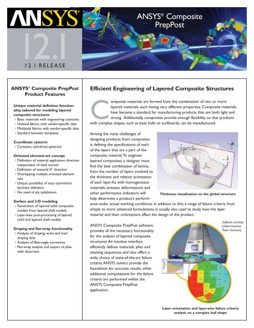
Among the many challenges of<br />
designing products from composites<br />
is defining the specifications of each<br />
of the layers that are a part of the<br />
composite material. To engineer<br />
layered composites, a designer must<br />
find the best combination of lamina,<br />
from the number of layers involved to<br />
the thickness and relative orientation<br />
of each layer. As with homogeneous<br />
materials, stresses, deformations and<br />
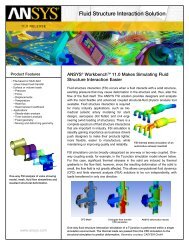
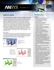
other performance indicators will Thickness visualization on the global structure<br />
help determine a product’s performance<br />
under actual working conditions. In addition to this, a range of failure criteria, from<br />
simple to more advanced formulations, is usually also used to study how the layer<br />
material and their orientations affect the design of the product.<br />
ANSYS <strong>Composite</strong> <strong>PrepPost</strong> software<br />
provides all the necessary functionality<br />
for the analysis of layered composite<br />
structures. An intuitive interface<br />
efficiently defines materials, plies and<br />
stacking sequences, and also offers a<br />
wide choice of state-of-the-art failure<br />
criteria. ANSYS solvers provide the<br />
foundation for accurate results, while<br />
additional computations for the failure<br />
criteria are performed within the<br />
ANSYS <strong>Composite</strong> <strong>PrepPost</strong><br />
application.<br />
Sailboat courtesy<br />
United Internet<br />
Team Germany<br />
Layer orientation and layer-wise failure criteria<br />
analysis on a complex hull shape
ANSYS <strong>Composite</strong> <strong>PrepPost</strong><br />
Product Features<br />
Comprehensive composite failure<br />
analysis capabilities<br />
4Inverse reserve factors (IRF), reserve<br />
factors (RF) and margin of safety (MOS)<br />
for composite failure criteria at all<br />
integration points of all layers<br />
4Arbitrary combinations of failure criteria<br />
• Max. strain, max. stress, Tsai-Wu,<br />
Tsai-Hill, Hashin, LaRC, Cuntze<br />
• Puck 2-D and 3-D for UD and weave<br />
materials<br />
• Core failure and face sheet wrinkling<br />
for sandwich structures<br />
4Multiple load case consideration<br />
• 4 result values per in-plane data point<br />
• Maximum IRF of all criteria of all layers<br />
• Active failure mode<br />
• Layer index with highest IRF<br />
• Critical load case<br />
4Simple definition, configuration and<br />
combination of desired composite failure<br />
criteria<br />
4Unique method to evaluate interlaminar<br />
normal 3-D stress in curved laminates<br />
based on shell elements<br />
4Element sampling enables ply-based strain,<br />
stress and IRF visualization<br />
4Result visualization for each ply of the<br />
laminate<br />
4Text plot highlights critical failure mode,<br />
layers and load case<br />
4Sensors for the evaluation of material<br />
quantity and cost<br />
4Python ® scripting interface (e.g., for<br />
user-specific failure criteria)<br />
Ply-book generation<br />
4Generation of individually formatted<br />
ply books in restructured text-format<br />
4Ply books can be exported in various<br />
formats (*.html, *.pdf, *.odt, etc.)<br />
Scripting and automation<br />
4Python scripting interface to automate<br />
model definition<br />
www.ansys.com<br />
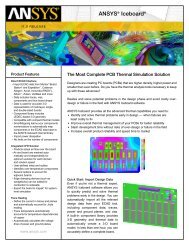
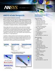
Results visualization on the global structure<br />
Overview of the user interface and<br />
material definitions<br />
ANSYS, Inc.<br />
Southpointe<br />
275 Technology Drive<br />
Canonsburg, PA 15317<br />
U.S.A.<br />
724.746.3304<br />
ansysinfo@ansys.com<br />
Toll Free U.S.A./Canada:<br />
1.866.267.9724<br />
Toll Free Mexico:<br />
001.866.267.9724<br />
Europe:<br />
44.870.010.4456<br />
eu.sales@ansys.com<br />
<strong>12.1</strong> RELEASE<br />
The post-processing capabilities of<br />
ANSYS <strong>Composite</strong> <strong>PrepPost</strong> software<br />
allow an in-depth investigation of a<br />
product’s behavior. The results for the<br />
structure can be looked at globally or<br />
viewed in detail down to the layer level,<br />
which enables users to accurately<br />
identify reasons a structure could<br />
potentially fail. Design iterations can<br />
easily be performed to take into account<br />
geometric changes or material variations.<br />
Useful for the analysis of an end product,<br />
the draping capabilities of ANSYS<br />
<strong>Composite</strong> <strong>PrepPost</strong> software allow<br />
users to correctly identify the exact<br />
orientation of every layer of the<br />
composite. A flat-wrap capability and<br />
the ability to create ply books help in<br />
product manufacturing.<br />
The product works with the<br />
ANSYS ® Mechanical interface in the<br />
ANSYS ® Workbench environment<br />
and composite structure designs can be<br />
automated through its integration with the ANSYS Mechanical APDL interface for<br />
advanced scripting.<br />
The ANSYS Advantage<br />
With the unequalled depth and unparalleled breadth of engineering simulation solutions<br />
from ANSYS, companies are transforming their leading edge design concepts into innovative<br />
products and processes that work. Today, 97 of the top 100 industrial companies on<br />
the “FORTUNE Global 500” invest in engineering simulation as a key strategy to win in a<br />
globally competitive environment.They choose ANSYS as their simulation partner,<br />
deploying the world’s most comprehensive multiphysics solutions to solve their complex<br />
engineering challenges. The engineered scalability of our solutions delivers the flexibility<br />
customers need within an architecture that is adaptable to the processes and design<br />
systems of their choice. No wonder the world’s most successful companies turn to<br />
ANSYS — with a track record of almost 40 years as the industry leader — for the best<br />
in engineering simulation.<br />
ANSYS, ANSYS Workbench, HPSS, AUTODYN, CFX, FLUENT and any and all ANSYS, Inc. brand,<br />
product, service and feature names, logos and slogans are registered trademarks or trademarks of<br />
ANSYS, Inc. or its subsidiaries in the United States or other countries. ICEM CFD is a trademark used<br />
under license. All other brand, product, service and feature names or trademarks are the property of<br />
their respective owners.<br />
Image Credits: Some images courtesy FluidDA nv, Forschungszentrum Joülich GmbH, Heat Transfer<br />
Research, Inc., Riello SPA and iStockphoto.com<br />
© 2009 ANSYS, Inc. All Rights Reserved. Printed in U.S.A. MKT0000468 11-09