FLENDER gear Units - DS TECH
FLENDER gear Units - DS TECH
FLENDER gear Units - DS TECH

You also want an ePaper? Increase the reach of your titles
YUMPU automatically turns print PDFs into web optimized ePapers that Google loves.
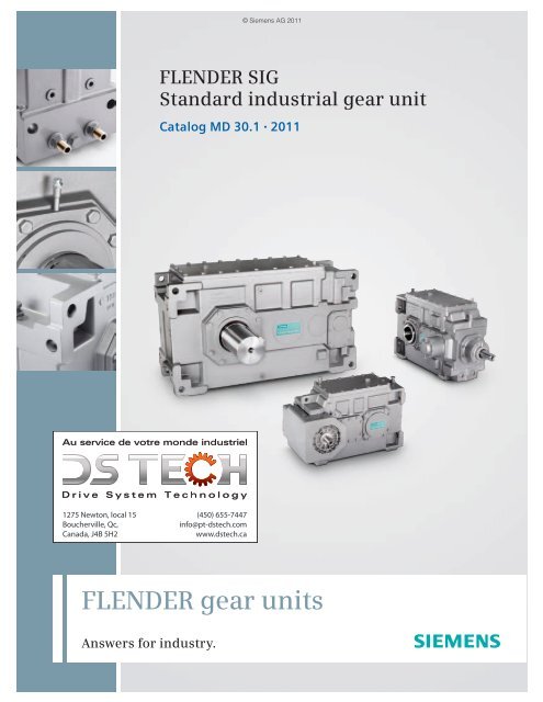
© Siemens AG 2011<br />
<strong>FLENDER</strong> SIG<br />
Standard industrial <strong>gear</strong> unit<br />
Catalog MD 30.1 2011<br />
1275 Newton, local 15<br />
Boucherville, Qc,<br />
Canada, J4B 5H2<br />
(450) 655-7447<br />
info@pt-dstech.com<br />
www.dstech.ca<br />
<strong>FLENDER</strong> <strong>gear</strong> units<br />
Answers for industry.
© Siemens AG 2011<br />
Related catalogs<br />
<strong>FLENDER</strong> Couplings MD 10.1<br />
Standard couplings<br />
Girth Gear <strong>Units</strong> MD 20.4<br />
for Tube Mills<br />
E86060-K5710-A111-A4-7600<br />
ARPEX MD 10.5<br />
Composite Couplings<br />
E86060-K5720-A141-A1-7400<br />
Paper Machine Drives MD 20.5<br />
E86060-K5710-A151-A2-7400<br />
ARPEX MD 10.9<br />
High Performance Couplings<br />
E86060-K5720-A151-A1-6300<br />
Conveyor Drives MD 20.6<br />
E86060-K5710-A191-A2-7400<br />
ARPEX MD 10.10<br />
Couplings Miniature<br />
E86060-K5720-A161-A2-6300<br />
Marine Reduction Gearboxes MD 20.7<br />
E86060-K5710-A211-A2-6300<br />
ARPEX MD 10.11<br />
Torque Limiters<br />
E86060-K5720-A171-A1-7400<br />
Products for Automation and Drives CA 01<br />
E86060-K5710-A221-A2-7400<br />
DVD:<br />
E86060-D4001-A510-C9-7600<br />
Gear <strong>Units</strong> MD 20.1<br />
Sizes 3–22<br />
Mall<br />
Information and ordering platform<br />
iin the Internet:<br />
E86060-K5720-A111-A2-6300<br />
www.siemens.com/industrymall<br />
Gear <strong>Units</strong> MD 20.11<br />
Sizes 23–28<br />
E86060-K5720-A211-A1-6300<br />
Bucket Elevator Drives MD 20.2<br />
E86060-K5720-A121-A2-6300<br />
PLANUREX 2 MD 20.3<br />
Planetary Gear <strong>Units</strong><br />
E86060-K5720-A131-A2-6300
© Siemens AG 2011<br />
<strong>FLENDER</strong> <strong>gear</strong> units<br />
<strong>FLENDER</strong> SIG<br />
Standard industrial <strong>gear</strong> unit<br />
Catalog MD 30.1 · 2011<br />
Introduction<br />
1<br />
Technical information<br />
2<br />
Design of the <strong>gear</strong> units<br />
3<br />
The products and systems<br />
listed in this catalog<br />
are manufactured<br />
and marketed using a<br />
certified quality management<br />
system complying<br />
with DIN EN ISO 9001<br />
(Certificate Registration<br />
No. 01 100 000708).<br />
The certificate is recognized<br />
in all IQNet countries.<br />
Helical <strong>gear</strong> units<br />
4<br />
horizontal mounting position<br />
Bevel-helical <strong>gear</strong> units<br />
5<br />
horizontal mounting position<br />
1275 Newton, local 15<br />
Boucherville, Qc,<br />
Canada, J4B 5H2<br />
© Siemens AG 2011<br />
Connection dimensions<br />
6<br />
Options for operation<br />
7<br />
Motor connection<br />
8<br />
Appendix<br />
9<br />
(450) 655-7447<br />
info@pt-dstech.com<br />
www.dstech.ca<br />
PEFC/04-31-1522<br />
Printed on paper from<br />
constantly managed forests<br />
and controlled sources.<br />
www.pefc.org
Answers for industry.<br />
The central task in drive engineering is to optimize interoperation of<br />
(450) 655-7447<br />
info@pt-dstech.com<br />
www.dstech.ca<br />
the controller, frequency converter, motor, coupling and <strong>gear</strong> unit.<br />
Through many years of system expertise, well-proven, standardized<br />
and reliable solutions have been available from Siemens over the<br />
long term. During the development of the new <strong>FLENDER</strong> SIG series of<br />
industrial <strong>gear</strong> units the main focus of the design engineers was also<br />
on the drive train.<br />
<strong>FLENDER</strong> SIG offers a number of innovative<br />
features: Up to 15 % more torque than the<br />
highly developed Flender <strong>gear</strong> units is<br />
really impressive. The new series is extremely<br />
versatile, and suitable for use in<br />
numerous applications. It offers a high<br />
degree of flexibility in system planning and<br />
many advantages in daily operation.<br />
Further benefits are the extended standards<br />
for add-on parts and peripherals as<br />
well as an additional mounting surface.<br />
Various different cooling solutions are also<br />
available as options for <strong>FLENDER</strong> SIG. The<br />
harmonized torque stages mean that you<br />
will be closer to your desired torque across<br />
the entire spectrum, with positive effects<br />
on costs and logistics.<br />
The <strong>FLENDER</strong> SIG product range is extensive<br />
even now. This catalog will provide you<br />
with an overview.<br />
1275 Newton, local 15<br />
Boucherville, Qc,<br />
Canada, J4B 5H2<br />
2 Siemens MD 30.1 · 2011
Introduction<br />
© Siemens AG 2011<br />
1<br />
1/2 Notes<br />
1/2 Summary of basic types<br />
1/3 Characteristic features<br />
1/3 Notes on selection and operation<br />
(450) 655-7447<br />
info@pt-dstech.com<br />
www.dstech.ca<br />
1275 Newton, local 15<br />
Boucherville, Qc,<br />
Canada, J4B 5H2<br />
Siemens MD 30.1 · 2011
Introduction<br />
Notes<br />
© Siemens AG 2011<br />
1 ■ Overview<br />
Summary of basic types<br />
Horizontal mounting position<br />
Helical <strong>gear</strong> units<br />
Types H2.., H3.., H4..<br />
2- ... 4-stage, i N = 6.3 – 400<br />
H.SH H.HH H.DH<br />
G_MD30_XX_00060 G_MD30_XX_00061 G_MD30_XX_00062<br />
Bevel-helical <strong>gear</strong> units<br />
Types B3.., B4..<br />
3- ... 4-stage, i N = 14 – 355<br />
B.SH B.HH B.DH<br />
Structure of types<br />
Type<br />
Type Helical <strong>gear</strong> unit H<br />
Structure of <strong>gear</strong> unit size<br />
Bevel-helical <strong>gear</strong> unit<br />
No. of stages 2 2<br />
Output shaft<br />
design<br />
3 3<br />
4 4<br />
Solid shaft<br />
Hollow shaft with keyway<br />
to DIN 6885/1<br />
Hollow shaft for shrink disk<br />
B 3 S H<br />
Mounting Horizontal H<br />
Gear unit size 5 1 1<br />
B<br />
S<br />
H<br />
D<br />
G_MD30_XX_00063 G_MD30_XX_00064 G_MD30_XX_00065<br />
Gear unit size •504 5 0 4<br />
•505 5 0 5<br />
•506 5 0 6<br />
•507 5 0 7<br />
•508 5 0 8<br />
•509 5 0 9<br />
•510 5 1 0<br />
•511 5 1 1<br />
•512 5 1 2<br />
•513 5 1 3<br />
•514 5 1 4<br />
(450) 655-7447<br />
info@pt-dstech.com<br />
www.dstech.ca<br />
Further details required in orders<br />
•Transmission ratio i<br />
•Designs A, B, C, D, etc.<br />
Example B3SH 511<br />
•Bevel-helical <strong>gear</strong> unit, 3-stage<br />
•Design A<br />
• i = 16<br />
•Solid output shaft design<br />
•Horizontal mounting position<br />
• Size 511<br />
1275 Newton, local 15<br />
Boucherville, Qc,<br />
Canada, J4B 5H2<br />
1/2 Siemens MD 30.1 · 2011
© Siemens AG 2011<br />
1275 Newton, local 15<br />
Boucherville, Qc,<br />
Canada, J4B 5H2<br />
■ Overview<br />
Characteristic features<br />
Design<br />
<strong>FLENDER</strong> SIG <strong>gear</strong> units are a completely new design.<br />
Advantages are:<br />
• Even more torque for the same size<br />
• Even greater flexibility through additional mounting positions<br />
• Even greater plant availability thanks to longer rolling bearing<br />
service life<br />
• Even closer to the customer's desired torque thanks to<br />
considerably harmonized torque stages<br />
• Wide range of variants from 5 types with solid shaft or different<br />
hollow shaft designs<br />
• Available, if required, with dust-tight taconite seals<br />
• Internal cooling or standardized fan mounting, as required<br />
• Fast availability worldwide<br />
• Attractive price/performance ratio<br />
• Higher operational reliability combined with increased power<br />
density<br />
Mounting position<br />
• <strong>FLENDER</strong> SIG <strong>gear</strong> units are available for horizontal<br />
installation.<br />
• Other arrangements are also possible on request. The basic<br />
<strong>gear</strong> unit can be optimally adapted to customer requirements<br />
by fitting different add-on pieces like motor bell housings, <strong>gear</strong><br />
unit swing-bases or backstops.<br />
Noise behavior<br />
New concepts were applied to clearly improve the noise<br />
emission of the <strong>FLENDER</strong> SIG <strong>gear</strong> units by<br />
• Grinding the bevel <strong>gear</strong>s<br />
• Optimizing the wheel set<br />
• Developing a compact monoblock housing<br />
• Achieving exceptionally large contact ratios.<br />
Thermal conduction<br />
<strong>FLENDER</strong> SIG <strong>gear</strong> units not only have a high efficiency but also<br />
a favorable thermal conduction<br />
• Through enlarged housing surface areas<br />
• Because large fans incorporating a new type of air conduction<br />
fan cowl are being used.<br />
The selection of <strong>gear</strong> units is based on a lower maximum oil<br />
temperature. By that, the operational reliability will be increased<br />
and the cost of maintenance reduced due to longer oil change<br />
intervals.<br />
Storing<br />
<strong>FLENDER</strong> SIG <strong>gear</strong> units have been designed according to a<br />
new unit construction principle. Through this, the variety of parts<br />
could be reduced. The parts are mainly on stock enabling the<br />
Siemens manufacturing plants worldwide to deliver at short<br />
term.<br />
■ Overview<br />
Introduction<br />
Notes<br />
Characteristic features<br />
Notes on selection and operation<br />
Notes on selection and operation<br />
• Illustrations are examples only and are not strictly binding.<br />
Dimensions are subject to change.<br />
•The weights are mean values and not strictly binding.<br />
•To prevent accidents, all rotating parts should be guarded<br />
according to local and national safety regulations.<br />
• Prior to commissioning, the operating instructions must be<br />
observed. The <strong>gear</strong> units are delivered ready for operation but<br />
without oil filling.<br />
•Oil quantities given are guide values only.<br />
The exact quantity of oil depends on the marks on the oil<br />
dipstick.<br />
•The oil viscosity has to correspond to the data given on the<br />
name plate.<br />
• Approved lubricants may be used only. You will find current<br />
operating instructions and lubricant selection tables on the<br />
Internet at:<br />
http://support.automation.siemens.com/WW/view/en/44231658<br />
• The <strong>gear</strong> units are supplied with radial shaft seals. Other<br />
sealing variants are available on request.<br />
•Directions of rotation refer to the output shaft d 2 .<br />
•In case of outdoor installation, insolation is to be avoided. The<br />
customer has to provide adequate protection.<br />
Explanation of symbols used in the dimensioned drawings:<br />
Symbol<br />
Foundation bolts of min. property class 8.8. Tolerance of the<br />
clearance holes in the housing acc. to DIN EN 20273 - ”coarse”<br />
series. The <strong>gear</strong> housings are protected against corrosion and<br />
lacquered in the color RAL 5015.<br />
Certified acc. to DIN EN ISO 9001<br />
Explanation<br />
Oil dipstick<br />
Breather<br />
Oil drain<br />
Oil filler<br />
1<br />
(450) 655-7447<br />
info@pt-dstech.com<br />
www.dstech.ca<br />
Siemens MD 30.1 · 2011<br />
1/3
Introduction<br />
© Siemens AG 2011<br />
1<br />
Notes<br />
(450) 655-7447<br />
info@pt-dstech.com<br />
www.dstech.ca<br />
1275 Newton, local 15<br />
Boucherville, Qc,<br />
Canada, J4B 5H2<br />
1/4 Siemens MD 30.1 · 2011
© Siemens AG 2011<br />
Technical information<br />
2<br />
2/2 Preservation<br />
2/2 Selection of oil<br />
2/2 Maintenance<br />
2/2 Shaft misalignment<br />
(450) 655-7447<br />
info@pt-dstech.com<br />
www.dstech.ca<br />
1275 Newton, local 15<br />
Boucherville, Qc,<br />
Canada, J4B 5H2<br />
Siemens MD 30.1 · 2011
Technical information<br />
© Siemens AG 2011<br />
2<br />
Preservation, selection of oil,<br />
maintenance, shaft misalignment<br />
■ Overview<br />
Preservation<br />
The internal preservation of Siemens <strong>gear</strong> units is dependent on<br />
the oil used.<br />
For <strong>gear</strong> units with corrosion prevention, the following storage<br />
times are possible:<br />
Standard preservation Long-term preservation 1)<br />
Up to 6 months Up to 24 months 2)<br />
If the storage periods mentioned are exceeded, the anticorrosive<br />
agent in the <strong>gear</strong> unit is to be renewed.<br />
Selection of oil<br />
Siemens industrial <strong>gear</strong> units may be filled with oils from<br />
producers authorized by Siemens AG, the oil producer or<br />
supplier being responsible for the quality of the product. For the<br />
selection of oil grade and viscosity, the limits of application given<br />
in the table are to be taken into consideration.<br />
A minimum operating viscosity of 25 cSt must be ensured.<br />
Viscosity ISO-VG at<br />
40 °C in mm 2 /s (cSt)<br />
Dip lubrication:<br />
Up to 36 months 3)<br />
Minimum temperature limit in °C for<br />
dip lubrication<br />
Mineral oil<br />
VG 220 -15 -25<br />
VG 320 -12 -25<br />
VG 460 -10 -25<br />
Synthetic oil<br />
In case of dip lubrication, all parts to be lubricated are lying in<br />
the oil.<br />
If the temperatures are below the values as listed in the table, the<br />
oil must be heated.<br />
In case of dip lubrication, the oil temperature must not drop<br />
below the pour point of the selected oil.<br />
Shaft misalignment<br />
Shaft misalignment is the result of displacement during<br />
assembly and operation and, where machines constructed with<br />
two radial bearings each are rigidly coupled, will cause high<br />
loads being placed on the bearings. Elastic deformation of base<br />
frame, foundation and machine housing will lead to shaft<br />
misalignment which cannot be prevented, even by precise<br />
alignment. Furthermore, because individual components of the<br />
drive train heat up differently during operation, heat expansion<br />
of the machine housings causes shaft misalignment.<br />
Poorly aligned drives are often the cause of seal or rolling<br />
bearing failure. Alignment should be carried out by specialist<br />
personnel in accordance with Siemens operating instructions.<br />
Depending on the direction of the effective shaft misalignment a<br />
distinction is made between:<br />
<br />
<br />
Axial misalignment<br />
<br />
Angular misalignment<br />
<br />
The shaft misalignment expected must be taken into account on<br />
selecting the connection between the components and the input<br />
shaft or output shaft. Guidelines and limits for compensation of<br />
shaft misalignment can be obtained from the manufacturer.<br />
<br />
<br />
Radial misalignment<br />
(450) 655-7447<br />
info@pt-dstech.com<br />
www.dstech.ca<br />
Maintenance<br />
Compliance with the conditions for operation and installation is<br />
essential. To prevent damage to the <strong>gear</strong> unit or failure of the<br />
drive, regular inspection and maintenance must be performed<br />
as specified in the operating instructions.<br />
1) Not for <strong>gear</strong> units with labyrinth seals or diaphragm glands.<br />
2) Only if mineral oil or synthetic oil on PAO basis is used.<br />
3) Only if synthetic oil on PG basis is used.<br />
1275 Newton, local 15<br />
Boucherville, Qc,<br />
Canada, J4B 5H2<br />
2/2 Siemens MD 30.1 · 2011
© Siemens AG 2011<br />
Design of the <strong>gear</strong> units<br />
3<br />
Guidelines for selection<br />
3/2 Constant mechanical power rating<br />
3/4 Variable power rating<br />
3/5 Key to symbols<br />
3/6 Calculation example<br />
3/8 Service factors<br />
Overview tables<br />
3/10 Type H2<br />
3/16 Type H3<br />
3/22 Type H4<br />
3/26 Type B3<br />
3/32 Type B4<br />
3/36 Actual ratio H2, H3, H4<br />
3/37 Actual ratio B3, B4<br />
(450) 655-7447<br />
info@pt-dstech.com<br />
www.dstech.ca<br />
1275 Newton, local 15<br />
Boucherville, Qc,<br />
Canada, J4B 5H2<br />
Siemens MD 30.1 · 2011
Design of the <strong>gear</strong> units<br />
Guidelines for selection<br />
© Siemens AG 2011<br />
Constant mechanical power rating<br />
■ Overview<br />
1. Determination of <strong>gear</strong> unit type and size<br />
1.1 Find the transmission ratio<br />
n 1<br />
i s =<br />
n 2<br />
2. Determination of oil supply: Horizontal mounting position<br />
All parts to be lubricated are lying in the oil or are splash<br />
lubricated. Forced lubrication on request.<br />
1.2 Determine the nominal power rating of the <strong>gear</strong> unit<br />
3<br />
P 2N ≥ P 2 f 1 f 2<br />
It is not necessary to consult us, if:<br />
3.33<br />
P 2 ≥ P 2N<br />
1.3 Check the maximum torque<br />
e.g.: peak operating, starting or braking torque<br />
T A n 1<br />
P 2N = f 3<br />
9550<br />
Gear unit sizes and number of reduction stages are given in<br />
rating tables depending on i N and P 2N .<br />
1.4 Check whether additional forces on the output shaft<br />
are permissible; it is essential to consult Siemens!<br />
1.5 Check whether the actual ratio i as per tables on<br />
pages 3/36, 3/37 is acceptable<br />
(450) 655-7447<br />
info@pt-dstech.com<br />
www.dstech.ca<br />
1275 Newton, local 15<br />
Boucherville, Qc,<br />
Canada, J4B 5H2<br />
3/2 Siemens MD 30.1 · 2011
© Siemens AG 2011<br />
Design of the <strong>gear</strong> units<br />
Guidelines for selection<br />
Constant mechanical power rating<br />
■ Overview (continued)<br />
3. Determination of required thermal capacity P G<br />
Data required:<br />
Type<br />
Size<br />
Nominal ratio<br />
Ambient temperature<br />
Input speed (1000/1500/1800 rpm)<br />
For the calculation below, the following has been assumed:<br />
Gear unit with dip lubrication<br />
Operating cycle: 100 %<br />
Installation in a large hall (wind velocity ≥ 1.4 m/s)<br />
altitude up to 1000 m<br />
Gear unit with mineral oil ISO-VG460<br />
3<br />
Assumptions corresponding to operating conditions<br />
Assumptions deviating<br />
from operating conditions<br />
1) Without auxiliary cooling<br />
P G = P GA x f 4 x f 8<br />
P G = .........<br />
P GA = .........<br />
f 4 = .........<br />
(see pages 3/12 - 3/35)<br />
f 8 = .........<br />
P G < P 2: Auxiliary cooling is required<br />
2) Fan<br />
3) Cooling coil<br />
4) Fan and cooling coil<br />
5) Water-/ air-oil cooler<br />
P G ≥ P 2<br />
Gear unit without<br />
auxiliary cooling<br />
is sufficient<br />
1275 Newton, local 15<br />
Boucherville, Qc,<br />
Canada, J4B 5H2<br />
2) Fan possible<br />
P G = P GB x f 4 x f 8<br />
P G = .........<br />
P G < P 2: Auxiliary cooling is required<br />
3) Cooling coil<br />
4) Fan and cooling coil<br />
5) Water-/ air-oil cooler<br />
3) Cooling coil possible<br />
P G = P GC x f 5 x f 8<br />
P G = .........<br />
P GB = .........<br />
f 4 = .........<br />
P GC = .........<br />
f 5 = .........<br />
(see pages 3/12 - 3/35)<br />
f 8 = .........<br />
P G ≥ P 2<br />
(see pages 3/12 - 3/35) 1)<br />
f 8 = .........<br />
Gear unit with<br />
fan cooling<br />
is sufficient<br />
P G < P 2: Auxiliary cooling is required<br />
4) Fan and cooling coil<br />
5) Water-/ air-oil cooler<br />
P G ≥ P 2<br />
Gear unit with<br />
cooling coil<br />
is sufficient<br />
(450) 655-7447<br />
info@pt-dstech.com<br />
www.dstech.ca<br />
Recalculation with<br />
other<br />
assumptions:<br />
"X.CAT-NG"<br />
4) Fan and cooling coil possible<br />
P G = P GD x f 5 x f 8<br />
P G = .........<br />
P G < P 2: Auxiliary cooling is required<br />
5) Water-/ air-oil cooler<br />
P GD = .........<br />
f 5 = .........<br />
(see pages 3/12 - 3/35) 1)<br />
f 8 = .........<br />
P G ≥ P 2<br />
1) Values refer to a cooling water inlet temperature of 20 °C!<br />
Please consult the sales person responsible<br />
P G < P 2<br />
Variation of the following items is possible:<br />
Gear unit with<br />
Oil grade / viscosity / level<br />
selected<br />
Gear unit on foundation or shaft-mounted <strong>gear</strong> unit<br />
P G ≥ P 2<br />
cooling<br />
Application of an oil supply system<br />
is sufficient<br />
…<br />
The type of the possibly required auxiliary cooling is dependent on the operating conditions at the<br />
customer site (dust, cooling water connection, etc.)<br />
Gear unit with<br />
fan and<br />
cooling coil<br />
is sufficient<br />
G_MD30_EN_00048<br />
Siemens MD 30.1 · 2011<br />
3/3
3<br />
© Siemens AG 2011<br />
Design of the <strong>gear</strong> units<br />
Guidelines for selection<br />
Variable power rating<br />
■ Overview<br />
For driven machines with constant speeds and variable power<br />
ratings the <strong>gear</strong> unit can be designed according to the equivalent<br />
power rating. For this a working cycle where phases I, II...n<br />
require power P I , P II ... P n and the respective power ratings<br />
operate for time fractions X I , X II ...X n is taken as a basis. The<br />
equivalent power rating can be calculated from these specifications<br />
with the following formula:<br />
6.6 X I X II<br />
X n<br />
P 2eq = P 6.6 + P<br />
I II<br />
6.6 + ... P 6.6<br />
n<br />
100 100<br />
100<br />
The size of the <strong>gear</strong> unit can then be determined analogously to<br />
points 1.1 ... 1.5 and 3.<br />
The following applies:<br />
P 2N ≥ P 2eq f 1 f 2<br />
Then, when P 2N has been determined, the power and time fractions<br />
must be checked by applying the following requirements:<br />
• The individual power fractions P I , P II ... P n must be greater<br />
than 0.4 x P 2N .<br />
• The individual power fractions P I , P II ... P n must not exceed<br />
1.4 x P 2N .<br />
• If power fractions P I , P II ... P n are greater than P 2N , the sum of<br />
time fractions X I , X II ... X n must not exceed 10 %.<br />
If any one of the three requirements is not met, P 2eq must be<br />
recalculated.<br />
It must be borne in mind that a brief peak power rating not<br />
included in the calculation of P 2eq must not be greater than<br />
P max = 2 x P 2N .<br />
In applications where the torque is variable but the speed<br />
constant, the <strong>gear</strong> unit can be designed on the basis of the socalled<br />
equivalent torque.<br />
A <strong>gear</strong> unit design which is finite-life fatigue-resistant can be sufficient<br />
for certain applications, for example, sporadic operation<br />
(lockgate drives) or low output speeds (n 2
© Siemens AG 2011<br />
Design of the <strong>gear</strong> units<br />
Guidelines for selection<br />
Key to symbols<br />
1275 Newton, local 15<br />
Boucherville, Qc,<br />
Canada, J4B 5H2<br />
■ Overview<br />
Key to symbols<br />
Description Explanation Chapter/Page<br />
E D Operating cycle per hour in %<br />
(e.g. E D = 80 % per hour)<br />
f 1 Factor for driven machine 3/8<br />
f 2 Factor for prime mover 3/9<br />
f 3 Peak torque factor 3/9<br />
f 4 Thermal factors 3/9<br />
f 5 Thermal factors 3/9<br />
f 8 Oil supply factor 3/9<br />
i Actual ratio 3/36, 3/37<br />
i N<br />
i s<br />
n 1<br />
n 2<br />
Nominal ratio<br />
Required ratio<br />
Input speed (rpm)<br />
Output speed (rpm)<br />
P G Required thermal capacity 3/3<br />
P GA<br />
P GB<br />
P GC<br />
P GD<br />
P 2N<br />
P 2<br />
t<br />
T A<br />
T 2N<br />
P 2eq<br />
P I , P II , P n<br />
X I , X II , X n<br />
Thermal capacity for <strong>gear</strong> units without auxiliary cooling<br />
Thermal capacity for <strong>gear</strong> units with fan cooling<br />
Thermal capacity for <strong>gear</strong> units with built-in cooling coil<br />
Thermal capacity for <strong>gear</strong> units with built-in cooling coil and fan<br />
Nominal power rating of <strong>gear</strong> unit (kW), see rating tables<br />
Power rating of driven machine (kW)<br />
Ambient temperature (°C)<br />
Max. torque occurring on input shaft, e.g. peak operating, starting, or braking torque (Nm)<br />
Nominal output torque (kNm)<br />
Equivalent power rating (kW)<br />
Fractions of power rating (kW) obtained from service classification<br />
Fractions of time (%) obtained from service classification<br />
3<br />
(450) 655-7447<br />
info@pt-dstech.com<br />
www.dstech.ca<br />
Notes and legend for tables of<br />
thermal capacities<br />
* On request<br />
P GA (kW):<br />
Gear units without auxiliary cooling;<br />
Values refer to:<br />
Operating cycle 100 %,<br />
Installation in a large hall,<br />
Altitude up to 1000 m<br />
P GB (kW):<br />
Gear units with fan;<br />
Values refer to:<br />
Operating cycle 100 %,<br />
Installation in a large hall,<br />
Altitude up to 1000 m<br />
P GC (kW):<br />
Gear units with built-in cooling coil;<br />
Values refer to:<br />
Operating cycle 100 %,<br />
Installation in a large hall,<br />
Altitude up to 1000 m,<br />
Cooling water inlet temperature of 20 °C with<br />
unlimited cooling water outlet temperature.<br />
A recalculation with a limited cooling water outlet temperature is<br />
possible on request.<br />
P GD (kW):<br />
Gear units with fan and built-in cooling coil;<br />
Values refer to:<br />
Operating cycle 100 %,<br />
Installation in a large hall,<br />
Altitude up to 1000 m,<br />
Cooling water inlet temperature of 20 °C with<br />
unlimited cooling water outlet temperature.<br />
A recalculation with a limited cooling water outlet temperature is<br />
possible on request.<br />
Siemens MD 30.1 · 2011<br />
3/5
Design of the <strong>gear</strong> units<br />
Guidelines for selection<br />
© Siemens AG 2011<br />
3<br />
Calculation example<br />
■ Overview<br />
Known criteria for the calculation example<br />
Prime mover<br />
• Electric motor<br />
• Motor speed:<br />
• Max. starting torque:<br />
P 1 = 75 kW<br />
n 1 = 1500 rpm<br />
T a = 720 Nm<br />
Driven machine<br />
• Belt conveyor:<br />
P 2 = 66 kW<br />
• Speed:<br />
n 2 = 26 rpm<br />
• Duty:<br />
12 h/day<br />
• Starts per hour: 7<br />
• Operating cycle per hour: E D = 100 %<br />
• Ambient temperature: 30 °C<br />
• Installation in a large hall: Wind velocity ≥ 1.4 m/s<br />
• Altitude:<br />
Sea level<br />
Gear unit design<br />
• Bevel-helical <strong>gear</strong> unit<br />
• Mounting position:<br />
Horizontal<br />
• Output shaft d 2 : On right-hand side, design C,<br />
solid shaft<br />
• Direction of rotation of<br />
output shaft d 2 :<br />
ccw<br />
Required:<br />
•Type of <strong>gear</strong> unit<br />
• Gear unit size<br />
1. Determination of <strong>gear</strong> unit type and size<br />
1.1 Find the transmission ratio<br />
1.2 Determine the nominal power rating of the <strong>gear</strong> unit<br />
Selected from power rating table: type B3SH, <strong>gear</strong> unit size 509<br />
with P 2N = 102 kW.<br />
It is not necessary to consult us<br />
1.3 Check the starting torque<br />
2. Determination of oil supply<br />
Gear unit with dip lubrication<br />
i<br />
n 1<br />
s = = 1500 = 57.7<br />
n i N = 56<br />
2 26<br />
P 2N ≥ P 2 f 1 f 2 = 66 1.3 1 = 85.8 kW<br />
3.33 P 2 ≥ P 2N 3.33 66 = 219.8 kW > P 2N<br />
T A n 1 720 1500<br />
P 2N ≥ f 3 =<br />
9550<br />
9550<br />
P 2N = 102 kW > 73.5 kW<br />
0.65 = 73.5 kW<br />
(450) 655-7447<br />
info@pt-dstech.com<br />
www.dstech.ca<br />
1275 Newton, local 15<br />
Boucherville, Qc,<br />
Canada, J4B 5H2<br />
3/6 Siemens MD 30.1 · 2011
© Siemens AG 2011<br />
Design of the <strong>gear</strong> units<br />
Guidelines for selection<br />
Calculation example<br />
■ Overview (continued)<br />
3. Determination of required thermal capacity P G<br />
Data required:<br />
Type: B3SH<br />
Size: 509<br />
Nominal ratio: i N = 56<br />
Ambient temperature: t = 30 °C<br />
Input speed n 1 = 1500 rpm<br />
For the calculation below, the following has been assumed:<br />
Gear unit with dip lubrication<br />
Operating cycle: 100 %<br />
Installation in a large hall (wind velocity ≥ 1.4 m/s)<br />
altitude up to 1000 m<br />
Gear unit with mineral oil ISO-VG460<br />
3<br />
Assumptions corresponding to operating conditions<br />
Assumptions deviating<br />
from operating conditions<br />
1) Without auxiliary cooling<br />
P G = P GA x f 4 x f 8<br />
P G = 52.0 kW<br />
P GA = 59.1 kW (see page 3/30)<br />
f 4 = 0.88 f 8 = 1.0<br />
P G < P 2: Auxiliary cooling is required<br />
2) Fan<br />
3) Cooling coil<br />
4) Fan and cooling coil<br />
5) Water-/ air-oil cooler<br />
Gear unit with<br />
auxiliary cooling<br />
required<br />
1275 Newton, local 15<br />
Boucherville, Qc,<br />
Canada, J4B 5H2<br />
2) Fan possible<br />
P G = P GB x f 4 x f 8<br />
P G = 120.7 kW<br />
P G < P 2: Auxiliary cooling is required<br />
3) Cooling coil<br />
4) Fan and cooling coil<br />
5) Water-/ air-oil cooler<br />
3) Cooling coil possible<br />
P G = P GC x f 5 x f 8<br />
P G = 183.1 kW<br />
P GB = 137.2 kW (see page 3/30)<br />
f 4 = 0.88 f 8 = 1.0<br />
P G ≥ P 2<br />
P GC = 196.9 kW (see page 3/30) 1)<br />
f 5 = 0.93 f 8 = 1.0<br />
Gear unit with<br />
fan cooling<br />
is sufficient<br />
P G < P 2: Auxiliary cooling is required<br />
4) Fan and cooling coil<br />
5) Water-/ air-oil cooler<br />
P G ≥ P 2<br />
Gear unit with<br />
cooling coil<br />
is sufficient<br />
(450) 655-7447<br />
info@pt-dstech.com<br />
www.dstech.ca<br />
Recalculation with<br />
other<br />
assumptions:<br />
"X.CAT-NG"<br />
4) Fan and cooling coil possible<br />
P G = P GD x f 5 x f 8<br />
P G = 247.1 kW<br />
P G < P 2: Auxiliary cooling is required<br />
5) Water-/ air-oil cooler<br />
P GD = 265.8 kW (see page 3/30) 1)<br />
f 5 = 0.93 f 8 = 1.0<br />
P G ≥ P 2<br />
1) Values refer to a cooling water inlet temperature of 20 °C!<br />
Please consult the sales person responsible<br />
P G < P 2<br />
Variation of the following items is possible:<br />
Gear unit with<br />
Oil grade / viscosity / level<br />
selected<br />
Gear unit on foundation or shaft-mounted <strong>gear</strong> unit<br />
P G ≥ P 2<br />
cooling<br />
Application of an oil supply system<br />
is sufficient<br />
…<br />
The selected <strong>gear</strong> unit B3SH509 with i N = 56 must be equipped with suitable auxiliary cooling.<br />
Depending on the operating conditions at the customer site, a fan or cooling coil must be fitted.<br />
Gear unit with<br />
fan and<br />
cooling coil<br />
is sufficient<br />
G_MD30_EN_00049<br />
Siemens MD 30.1 · 2011<br />
3/7
Design of the <strong>gear</strong> units<br />
Guidelines for selection<br />
© Siemens AG 2011<br />
Service factors<br />
3<br />
■ Overview<br />
Factor for driven machines f 1<br />
Driven machines<br />
Effective operating period under<br />
load in hours<br />
≤ 0.5 > 0.5 – 10 > 10<br />
Waste water treatment<br />
•Thickeners(central drive) – – 1.2<br />
•Filter presses 1.0 1.3 1.5<br />
•Flocculation apparatus 0.8 1.0 1.3<br />
•Aerators – 1.8 2.0<br />
•Raking equipment 1.0 1.2 1.3<br />
•Combined longitudinal and rotary 1.0 1.3 1.5<br />
rakes<br />
•Pre-thickeners – 1.1 1.3<br />
•Screw pumps – 1.3 1.5<br />
•Water turbines – – 2.0<br />
Pumps<br />
•Centrifugal pumps 1.0 1.2 1.3<br />
•Positive-displacement pumps<br />
-1 piston 1.3 1.4 1.8<br />
-> 1 piston 1.2 1.4 1.5<br />
Dredgers<br />
•Bucket conveyors – 1.6 1.6<br />
•Dumping devices – 1.3 1.5<br />
•Caterpillar traveling <strong>gear</strong>s 1.2 1.6 1.8<br />
Bucket wheel excavators<br />
-as pick-up – 1.7 1.7<br />
-for primitive material – 2.2 2.2<br />
•Cutter heads – 2.2 2.2<br />
•Slewing <strong>gear</strong>s 1) – 1.4 1.8<br />
Plate bending machines 1) – 1.0 1.0<br />
Chemical Industry<br />
•Extruders – – 1.6<br />
•Dough mills – 1.8 1.8<br />
•Rubber calenders – 1.5 1.5<br />
•Cooling drums – 1.3 1.4<br />
Mixers for<br />
-uniform media 1.0 1.3 1.4<br />
-non-uniform media 1.4 1.6 1.7<br />
Agitators for media with<br />
-uniform density 1.0 1.3 1.5<br />
-non-uniform density 1.2 1.4 1.6<br />
-non-uniform gas absorption 1.4 1.6 1.8<br />
•Toasters 1.0 1.3 1.5<br />
•Centrifuges 1.0 1.2 1.3<br />
Metal working mills<br />
•Plate tilters 1.0 1.0 1.2<br />
•Ingot pushers 1.0 1.2 1.2<br />
•Winding machines – 1.6 1.6<br />
•Cooling bed transfer frames – 1.5 1.5<br />
•Roller straighteners – 1.6 1.6<br />
Roller tables<br />
-continuous – 1.5 1.5<br />
-intermittent – 2.0 2.0<br />
•Reversing tube mills – 1.8 1.8<br />
Shears<br />
-continuous 1) – 1.5 1.5<br />
-crank type 1) 1.0 1.0 1.0<br />
•Continuous casting drivers 1) – 1.4 1.4<br />
Design for power rating of driven machine P 2<br />
1) Designed power corresponding to max. torque<br />
2) Load can be exactly classified, for instance, according to FEM 1001<br />
3) A check for thermal capacity is absolutely essential<br />
Driven machines<br />
Effective operating period under<br />
load in hours<br />
≤ 0.5 > 0.5 – 10 > 10<br />
Rolls<br />
-Reversing blooming mills – 2.5 2.5<br />
-Reversing slabbing mills – 2.5 2.5<br />
-Reversing wire mills – 1.8 1.8<br />
-Reversing sheet mills – 2.0 2.0<br />
-Reversing plate mills – 1.8 1.8<br />
•Roll adjustment drives 0.9 1.0 –<br />
Conveyors<br />
•Bucket conveyors – 1.4 1.5<br />
•Hauling winches 1.4 1.6 1.6<br />
•Hoists – 1.5 1.8<br />
•Belt conveyors ≤ 150 kW 1.0 1.2 1.3<br />
•Belt conveyors ≥ 150 kW 1.1 1.3 1.4<br />
•Goods lifts 1) – 1.2 1.5<br />
•Passenger lifts 1) – 1.5 1.8<br />
•Apron conveyors – 1.2 1.5<br />
•Escalators 1.0 1.2 1.4<br />
•Railway vehicles – 1.5 –<br />
Frequency converters – 1.8 2.0<br />
Reciprocating compressors – 1.8 1.9<br />
Cranes 2)<br />
•Slewing <strong>gear</strong>s 1) 1.0 1.4 1.8<br />
•Luffing <strong>gear</strong>s 1.0 1.1 1.4<br />
•Traveling <strong>gear</strong>s 1.1 1.6 2.0<br />
•Hoisting <strong>gear</strong>s 1.0 1.1 1.4<br />
•Derricking jib cranes 1.0 1.2 1.6<br />
Cooling towers<br />
•Cooling tower fans – – 2.0<br />
•Blowers(axial and radial) – 1.4 1.5<br />
Food industry<br />
Cane sugar production<br />
•Cane knives 1) – – 1.7<br />
•Cane mills – – 1.7<br />
Beet sugar production<br />
•Beet cossettes macerators – – 1.2<br />
•Extraction plants, mechanical refrigerators<br />
– – 1.4<br />
•Juice boilers, sugar beet washing – – 1.5<br />
machines<br />
•Sugar beet cutters<br />
Paper machines<br />
•of all kinds 3) – 1.8 2.0<br />
•Pulper drives (on request)<br />
Centrifugal compressors – 1.4 1.5<br />
Cableways<br />
•Material ropeways – 1.3 1.4<br />
•To-and-fro system aerial ropeways – 1.6 1.8<br />
•T-bar lifts – 1.3 1.4<br />
•Continuous ropeways – 1.4 1.6<br />
Cement industry<br />
•Concrete mixers – 1.5 1.5<br />
•Breakers 1) – 1.2 1.4<br />
•Rotary kilns – – 2.0<br />
•Tube mills – – 2.0<br />
•Separators – 1.6 1.6<br />
•Roll crushers – – 2.0<br />
Note: The listed load parameters are empirical values. Prerequisite<br />
for their application is that the machinery and equipment<br />
mentioned correspond to generally accepted design and load<br />
specifications. In case of deviations from standard conditions,<br />
please contact us. For driven machines which are not listed in<br />
this table, please refer to us.<br />
(450) 655-7447<br />
info@pt-dstech.com<br />
www.dstech.ca<br />
1275 Newton, local 15<br />
Boucherville, Qc,<br />
Canada, J4B 5H2<br />
3/8 Siemens MD 30.1 · 2011
© Siemens AG 2011<br />
Design of the <strong>gear</strong> units<br />
Guidelines for selection<br />
Service factors<br />
■ Overview (continued)<br />
Factor for prime mover f 2<br />
1275 Newton, local 15<br />
Boucherville, Qc,<br />
Canada, J4B 5H2<br />
Factor for prime mover f 2<br />
Electric motors, hydraulic motors, 1.0<br />
turbines<br />
Piston engines 4 - 6 cylinders, 1.25<br />
cyclic variation 1 : 100 to 1: 200<br />
Piston engines 1 - 3 cylinders 1.5<br />
cyclic variation 1 : 100<br />
Peak torque factor f 3<br />
Peak torque factor f 3<br />
Load peaks per hour<br />
1 - 5 6 - 30 31 - 100 > 100<br />
Steady direction of load 0.5 0.65 0.7 0.85<br />
Alternating direction of load 0.7 0.95 1.10 1.25<br />
Thermal factor f 4<br />
(Gear units without auxiliary cooling or with fan)<br />
Ambient temperature<br />
10 °C 15 °C 20 °C 25 °C 30 °C 35 °C 40 °C 45 °C 50 °C<br />
Thermal 1.11 1.06 1.00 0.94 0.88 0.82 0.75 0.69 0.63<br />
factor f 4<br />
Thermal factor f 5<br />
(For cooling with cooling coil, or with fan and cooling coil)<br />
Ambient temperature<br />
10 °C 15 °C 20 °C 25 °C 30 °C 35 °C 40 °C 45 °C 50 °C<br />
Thermal 1.05 1.03 1.00 0.97 0.93 0.90 0.87 0.84 0.81<br />
factor f 5<br />
3<br />
Type of<br />
<strong>gear</strong> unit<br />
•H..H<br />
•B..H<br />
Oil supply factor f 8<br />
Oil supply<br />
Without<br />
auxiliary<br />
cooling<br />
With<br />
fan<br />
With cooling<br />
coil<br />
Dip lubrication 1 1 1 1<br />
With fan<br />
and cooling<br />
coil<br />
(450) 655-7447<br />
info@pt-dstech.com<br />
www.dstech.ca<br />
Siemens MD 30.1 · 2011<br />
3/9
3<br />
Design of the <strong>gear</strong> units<br />
Overview tables<br />
Type H2<br />
Nominal power ratings, <strong>gear</strong> unit sizes 504 to 514<br />
■ Technical data<br />
Nominal power ratings P 2N (kW) for H2<br />
Gear unit sizes<br />
© Siemens AG 2011<br />
i N n 1 n 2 504 505 506 507 508 509 510 511 512 513 514<br />
6.3 1800 286 208 343 – 648 – 1084 – 1851 – 3037 –<br />
1500 238 173 286 – 540 – 903 – 1543 – 2531 –<br />
1200 190 138 229 – 432 – 723 – 1234 – 2024 –<br />
1000 159 115 191 – 360 – 602 – 1028 – 1687 –<br />
7.1 1800 254 184 311 – 585 – 982 – 1672 – 2733 –<br />
1500 211 153 259 – 487 – 818 – 1393 – 2277 –<br />
1200 169 123 207 – 390 – 655 – 1115 – 1822 –<br />
1000 141 102 173 – 325 – 546 – 929 – 1518 –<br />
8 1800 225 167 270 – 517 672 855 1127 1505 1912 2450 2941<br />
1500 188 139 225 – 431 560 712 939 1254 1593 2042 2451<br />
1200 150 111 180 – 345 448 570 751 1003 1274 1634 1961<br />
1000 125 93 150 – 287 373 475 626 836 1062 1361 1634<br />
9 1800 200 152 244 346 463 607 766 1020 1348 1727 2186 2647<br />
1500 167 126 204 289 386 505 639 850 1124 1439 1822 2206<br />
1200 133 101 163 231 309 404 511 680 899 1151 1458 1765<br />
1000 111 84 136 192 257 337 426 567 749 959 1215 1471<br />
10 1800 180 135 221 314 414 537 683 888 1202 1554 1939 2373<br />
1500 150 112 184 262 345 447 570 740 1001 1295 1616 1978<br />
1200 120 90 147 209 276 358 456 592 801 1036 1293 1582<br />
1000 100 75 123 174 230 298 380 493 668 863 1077 1319<br />
11.2 1800 161 122 195 272 358 480 602 796 1064 1393 1708 2118<br />
1500 134 101 163 227 298 400 502 664 887 1160 1424 1765<br />
1200 107 81 130 182 239 320 401 531 709 928 1139 1412<br />
1000 89 68 109 151 199 267 334 442 591 774 949 1177<br />
12.5 1800 144 104 175 247 320 429 531 710 924 1241 1518 1879<br />
1500 120 87 145 206 267 358 443 592 770 1034 1265 1565<br />
1200 96 70 116 165 213 286 354 473 616 827 1012 1252<br />
1000 80 58 97 137 178 238 295 394 513 689 844 1044<br />
14 1800 129 94 153 223 284 372 477 625 825 1099 1330 1654<br />
1500 107 78 127 186 236 310 397 521 688 916 1108 1379<br />
1200 86 62 102 149 189 248 318 417 550 733 886 1103<br />
1000 71 52 85 124 158 206 265 347 458 610 739 919<br />
16 1800 113 83 136 198 253 332 429 552 751 954 1171 1471<br />
1500 94 70 113 165 210 277 358 460 626 795 976 1226<br />
1200 75 56 90 132 168 221 286 368 501 636 781 980<br />
1000 63 46 75 110 140 185 238 307 417 530 651 817<br />
18 1800 100 74 121 176 235 294 382 496 662 852 1093 1288<br />
1500 83 62 101 147 196 245 318 413 551 710 911 1073<br />
1200 67 49 81 118 157 196 255 330 441 568 729 859<br />
1000 56 41 67 98 130 164 212 275 368 473 607 715<br />
20 1800 90 66 – 154 – 262 – 446 – 776 – 1134<br />
1500 75 55 – 129 – 218 – 372 – 647 – 945<br />
1200 60 44 – 103 – 175 – 297 – 517 – 756<br />
1000 50 37 – 86 – 146 – 248 – 431 – 630<br />
22.4 1800 80 – – 137 – 244 – 397 – 683 – 1059<br />
1500 67 – – 114 – 203 – 331 – 569 – 882<br />
1200 54 – – 91 – 162 – 265 – 455 – 706<br />
1000 45 – – 76 – 135 – 221 – 379 – 588<br />
25 1800 72 – – 122 – – – – – – – –<br />
1500 60 – – 102 – – – – – – – –<br />
1200 48 – – 81 – – – – – – – –<br />
1000 40 – – 68 – – – – – – – –<br />
(450) 655-7447<br />
info@pt-dstech.com<br />
www.dstech.ca<br />
1275 Newton, local 15<br />
Boucherville, Qc,<br />
Canada, J4B 5H2<br />
3/10 Siemens MD 30.1 · 2011
© Siemens AG 2011<br />
Design of the <strong>gear</strong> units<br />
Overview tables<br />
Type H2 – Nominal output torques<br />
Gear unit sizes 504 to 514<br />
1275 Newton, local 15<br />
Boucherville, Qc,<br />
Canada, J4B 5H2<br />
■ Technical data (continued)<br />
Nominal output torques T 2N (kNm) Type H2<br />
Gear unit sizes<br />
i N 504 505 506 507 508 509 510 511 512 513 514 Type<br />
6.3 7 11.6 – 21.5 – 37 – 63.5 – 101.5 –<br />
7.1 7 11.6 – 21.5 – 37 – 63.5 – 101.5 –<br />
8 7 11.6 – 21.5 28.3 37 48.5 63.5 81 101.5 125<br />
9 7 11.6 16.2 21.5 28.3 37 48.5 63.5 81 101.5 125<br />
10 7 11.6 16.2 21.5 28.3 37 48.5 63.5 81 101.5 125<br />
11.2 7 11.6 16.2 21.5 28.3 37 48.5 63.5 81 101.5 125<br />
12.5 7 11.6 16.2 21.5 28.3 37 48.5 63.5 81 101.5 125<br />
14 7 11.6 16.2 21.5 28.3 37 48.5 63.5 81 101.5 125<br />
16 7 11.6 16.2 21.5 28.3 37 48.5 63.5 81 101.5 125<br />
18 7 11.6 16.2 21.5 28.3 37 48.5 63.5 81 101.5 125<br />
20 7 11.6 16.2 21.5 28.3 37 48.5 63.5 81 101.5 125<br />
22.4 – 11.6 16.2 21.5 28.3 37 48.5 63.5 81 101.5 125<br />
25 – 11.6 16.2 21.5 28.3 37 48.5 63.5 81 101.5 125<br />
28 – 11.6 16.2 21.5 28.3 37 48.5 63.5 81 101.5 125<br />
31.5 – 11.6 16.2 21.5 28.3 37 48.5 63.5 81 101.5 125<br />
35.5 – 11.6 16.2 21.5 28.3 37 48.5 63.5 81 101.5 125<br />
40 – 11.6 16.2 21.5 28.3 37 48.5 63.5 81 101.5 125<br />
45 – 11.6 16.2 21.5 28.3 37 48.5 63.5 81 101.5 125<br />
50 – 11.6 16.2 21.5 28.3 37 48.5 63.5 81 101.5 125<br />
56 – 11.6 16.2 21.5 28.3 37 48.5 63.5 81 101.5 125<br />
63 – 11.6 16.2 21.5 28.3 37 48.5 63.5 81 101.5 125<br />
71 – 11.6 16.2 21.5 28.3 37 48.5 63.5 81 101.5 125<br />
80 – – 16.2 21.5 28.3 37 48.5 63.5 81 101.5 125<br />
90 – – 16.2 21.5 28.3 37 48.5 63.5 81 101.5 125<br />
100 – – 16.2 21.5 28.3 37 48.5 63.5 81 101.5 125<br />
112 – – – 21.5 28.3 37 48.5 63.5 81 101.5 125<br />
125 – – – 21.5 28.3 37 48.5 63.5 81 101.5 125<br />
140 – – – 21.5 28.3 37 48.5 63.5 81 101.5 125<br />
160 – – – 21.5 28.3 37 48.5 63.5 81 101.5 125<br />
180 – – – 21.5 28.3 37 48.5 63.5 81 101.5 125<br />
200 – – – 21.5 28.3 37 48.5 63.5 81 101.5 125<br />
224 – – – 21.5 28.3 37 48.5 63.5 81 101.5 125<br />
250 – – – 21.5 28.3 37 48.5 63.5 81 101.5 125<br />
280 – – – 21.5 28.3 37 48.5 63.5 81 101.5 125<br />
315 – – – – 28.3 37 48.5 63.5 81 101.5 125<br />
355 – – – – 28.3 – 48.5 – 81 – 125<br />
400 – – – – – – 48.5 – 81 – 125<br />
H2<br />
H3<br />
H4<br />
3<br />
(450) 655-7447<br />
info@pt-dstech.com<br />
www.dstech.ca<br />
Type H3, see page 3/17<br />
Type H4, see page 3/23<br />
Siemens MD 30.1 · 2011<br />
3/11
Design of the <strong>gear</strong> units<br />
Overview tables<br />
Type H2 – Thermal capacities<br />
n 1 = 1000 rpm<br />
© Siemens AG 2011<br />
3<br />
■ Technical data (continued)<br />
Thermal capacities P G. (kW) Type H2<br />
Gear unit sizes<br />
i N 504 505 506 507 508 509 510 511 512 513 514<br />
6.3 P GA 56.7 70.8 – 97.5 – 122.5 – 140.0 – 155.5 –<br />
P GB 120.9 148.9 – 232.3 – 293.5 – 472.3 – 559.5 –<br />
P GC 122.6 248.6 – 296.8 – 537.9 – 634.4 – 1038.6 –<br />
P GD 181.1 315.4 – 417.5 – 682.1 – 919.8 – 1361.9 –<br />
7.1 P GA 56.5 69.7 – 96.7 – 124.7 – 150.9 – 182.4 –<br />
P GB 119.0 144.9 – 225.1 – 289.2 – 466.2 – 563.3 –<br />
P GC 118.8 236.8 – 284.5 – 515.6 – 608.3 – 1005.1 –<br />
P GD 175.9 300.7 – 398.4 – 655.6 – 883.4 – 1315.3 –<br />
8 P GA 55.2 69.3 – 91.9 110.4 128.4 137.1 158.4 162.2 201.2 189.7<br />
P GB 115.2 141.9 – 209.5 255.5 286.0 316.3 457.5 511.5 561.3 612.9<br />
P GC 113.7 226.0 – 258.3 315.3 497.8 430.1 587.1 799.2 964.5 1083.2<br />
P GD 168.5 288.6 – 363.4 444.1 633.0 589.7 847.5 1096.2 1259.3 1426.2<br />
9 P GA 53.6 67.3 81.7 94.9 109.1 126.0 138.5 162.4 172.6 211.9 214.2<br />
P GB 110.4 136.1 165.8 213.6 247.2 275.2 310.6 445.8 503.4 551.3 615.1<br />
P GC 107.9 212.5 192.8 259.2 299.6 468.1 415.1 559.8 766.7 916.6 1050.1<br />
P GD 160.4 272.2 268.6 364.8 423.1 597.2 567.8 806.8 1048.5 1194.2 1378.9<br />
10 P GA 50.3 65.2 80.1 89.7 103.3 123.1 141.8 163.5 178.2 218.0 231.0<br />
P GB 102.8 130.4 160.6 198.0 229.2 263.0 308.4 429.5 493.6 534.3 609.6<br />
P GC 99.0 200.8 183.9 235.7 272.8 436.1 400.8 525.8 733.6 863.3 1002.2<br />
P GD 147.4 257.1 256.6 333.8 386.7 559.6 549.1 761.2 1003.2 1124.5 1315.9<br />
11.2 P GA 51.2 62.2 79.4 89.8 106.7 124.0 139.1 165.7 181.9 234.7 240.2<br />
P GB 103.7 121.3 157.3 192.6 233.7 259.1 295.9 413.6 479.5 531.8 595.8<br />
P GC 98.8 184.4 177.3 224.0 274.2 427.8 379.6 495.1 693.7 841.5 957.4<br />
P GD 146.8 235.2 247.2 316.8 387.8 545.1 518.9 715.1 952.0 1095.3 1250.6<br />
12.5 P GA 48.7 59.1 76.9 90.2 100.4 115.4 135.4 172.7 181.5 233.1 244.5<br />
P GB 96.7 114.4 150.3 186.7 216.6 236.9 282.7 406.2 461.2 513.1 576.4<br />
P GC 92.1 169.5 167.7 217.0 249.0 382.1 355.5 477.2 651.6 789.6 895.6<br />
P GD 136.5 217.7 234.3 304.4 355.0 487.9 488.0 684.2 893.8 1031.3 1172.5<br />
14 P GA 46.4 57.9 74.3 85.5 100.0 114.9 136.4 170.4 182.9 225.2 258.7<br />
P GB 91.5 110.8 144.4 175.7 210.9 231.9 278.2 391.0 444.0 481.9 571.9<br />
P GC 86.1 162.0 158.5 199.8 237.3 367.7 348.3 451.2 612.8 725.7 876.6<br />
P GD 127.9 207.9 222.2 281.3 337.8 471.2 475.3 649.8 838.6 942.6 1143.2<br />
16 P GA 44.4 57.0 70.4 79.9 100.2 113.0 126.6 164.1 189.6 230.6 255.6<br />
P GB 86.3 105.9 134.1 164.2 204.3 222.3 254.1 377.6 434.6 473.3 550.2<br />
P GC 81.1 151.9 146.1 183.4 228.8 346.2 311.8 429.0 585.0 692.4 823.6<br />
P GD 119.8 195.1 204.2 260.0 323.2 442.5 426.3 621.9 801.0 902.2 1076.7<br />
18 P GA 42.4 53.7 66.8 74.9 94.8 107.3 125.3 155.8 185.9 219.0 245.7<br />
P GB 81.0 100.2 126.2 153.0 191.3 211.0 248.7 352.0 418.1 450.9 516.4<br />
P GC 75.4 140.9 135.0 169.4 210.8 323.8 302.0 393.4 553.0 654.5 752.6<br />
P GD 111.6 182.5 189.6 239.8 298.9 414.8 412.9 568.6 759.0 854.9 984.1<br />
20 P GA 40.9 – 65.4 – 88.6 – 123.1 – 179.1 – 250.4<br />
P GB 77.7 – 121.9 – 178.7 – 238.0 – 404.2 – 504.8<br />
P GC 71.4 – 129.1 – 193.8 – 285.0 – 527.7 – 721.5<br />
P GD 105.4 – 181.2 – 276.4 – 388.8 – 726.6 – 938.2<br />
22.4 P GA – – 63.8 – 83.0 – 117.0 – 169.7 – 238.2<br />
P GB – – 116.4 – 166.2 – 226.4 – 376.2 – 481.0<br />
P GC – – 122.5 – 178.7 – 266.1 – 479.2 – 680.6<br />
P GD – – 170.4 – 254.8 – 365.6 – 662.1 – 889.5<br />
25 P GA – – 60.1 – – – – – – – –<br />
P GB – – 110.2 – – – – – – – –<br />
P GC – – 114.2 – – – – – – – –<br />
P GD – – 160.1 – – – – – – – –<br />
For notes and legend for tables, see page 3/5<br />
(450) 655-7447<br />
info@pt-dstech.com<br />
www.dstech.ca<br />
1275 Newton, local 15<br />
Boucherville, Qc,<br />
Canada, J4B 5H2<br />
3/12 Siemens MD 30.1 · 2011
© Siemens AG 2011<br />
Design of the <strong>gear</strong> units<br />
Overview tables<br />
Type H2 – Thermal capacities<br />
n 1 = 1200 rpm<br />
1275 Newton, local 15<br />
Boucherville, Qc,<br />
Canada, J4B 5H2<br />
(450) 655-7447<br />
info@pt-dstech.com<br />
www.dstech.ca<br />
■ Technical data (continued)<br />
Thermal capacities P G. (kW) Type H2<br />
Gear unit sizes<br />
i N 504 505 506 507 508 509 510 511 512 513 514<br />
6.3 P GA 56.1 68.2 – 89.1 – 104.9 – 75.4 – 56.2 –<br />
P GB 135.7 165.1 – 254.7 – 315.8 – 490.2 – 564.6 –<br />
P GC 133.4 275.3 – 321.9 – 579.2 – 660.8 – 1089.1 –<br />
P GD 205.2 357.0 – 466.5 – 755.4 – 1007.1 – 1478.0 –<br />
7.1 P GA 56.6 67.9 – 90.3 – 110.7 – 102.5 – 99.3 –<br />
P GB 133.4 160.8 – 247.6 – 313.1 – 491.7 – 573.7 –<br />
P GC 129.5 262.6 – 306.9 – 558.8 – 643.0 – 1061.8 –<br />
P GD 198.9 341.0 – 446.0 – 728.7 – 973.4 – 1432.5 –<br />
8 P GA 55.5 68.6 – 87.5 102.7 118.2 119.6 121.4 101.7 131.8 96.4<br />
P GB 129.3 158.0 – 231.1 279.6 312.6 340.2 488.1 533.3 573.6 624.1<br />
P GC 123.9 249.6 – 280.2 340.5 540.4 458.7 622.9 844.7 1017.4 1151.9<br />
P GD 190.5 326.2 – 408.1 496.9 705.7 651.4 936.8 1202.7 1374.0 1555.1<br />
9 P GA 54.3 67.0 80.2 91.5 103.4 119.1 125.2 133.6 126.0 161.6 137.1<br />
P GB 124.6 151.9 184.2 236.3 272.2 302.3 336.2 480.0 533.4 574.3 631.0<br />
P GC 117.9 236.4 209.6 281.2 323.1 509.9 444.1 595.4 819.3 981.7 1109.4<br />
P GD 182.2 308.9 302.5 410.1 474.4 665.4 629.0 895.6 1159.4 1309.1 1505.2<br />
10 P GA 51.3 65.3 79.1 87.4 99.4 118.0 132.7 141.0 142.9 180.7 166.0<br />
P GB 115.9 145.8 178.8 220.2 253.7 289.3 336.2 465.6 528.9 565.3 628.8<br />
P GC 108.5 221.9 201.1 256.6 295.5 478.1 430.6 564.7 788.3 922.3 1063.3<br />
P GD 167.6 291.5 290.1 375.9 433.7 625.9 610.5 845.8 1112.4 1239.1 1439.1<br />
11.2 P GA 52.5 63.1 79.4 89.1 104.0 121.4 132.6 150.4 154.1 212.9 192.5<br />
P GB 117.2 136.1 175.4 214.8 259.4 285.7 325.4 453.1 517.9 570.9 624.6<br />
P GC 108.0 203.9 193.0 244.9 297.4 469.6 408.6 533.6 748.4 910.1 1016.6<br />
P GD 167.6 267.4 279.2 357.4 436.9 611.4 579.8 799.4 1058.5 1213.2 1374.5<br />
12.5 P GA 50.3 60.4 77.2 91.7 98.7 114.3 131.0 165.3 160.6 218.0 208.8<br />
P GB 109.6 128.6 168.5 209.8 240.9 263.0 311.6 448.6 501.5 554.8 611.9<br />
P GC 101.6 188.2 183.0 238.0 271.0 418.9 384.1 516.1 708.2 860.2 961.9<br />
P GD 155.5 247.9 264.6 344.3 399.3 548.3 545.7 768.4 998.8 1146.4 1294.3<br />
14 P GA 48.1 59.6 75.1 87.4 100.0 114.9 134.4 166.2 169.0 216.5 239.9<br />
P GB 103.8 124.8 161.7 197.3 234.5 258.4 307.3 434.4 486.5 526.0 616.2<br />
P GC 94.6 179.8 173.5 219.6 258.5 403.6 378.7 493.1 661.3 790.9 951.8<br />
P GD 145.8 236.8 251.7 318.6 381.0 530.8 532.5 731.1 939.8 1053.7 1269.2<br />
16 P GA 46.3 59.3 72.0 81.2 101.9 114.9 125.9 159.5 182.9 230.1 243.3<br />
P GB 98.0 120.0 150.2 184.2 229.2 248.8 281.8 418.6 481.0 519.7 597.2<br />
P GC 88.9 169.6 159.9 201.3 250.9 382.0 339.5 469.5 641.2 761.7 896.7<br />
P GD 136.8 222.3 231.4 294.5 366.3 498.7 479.0 698.9 899.6 1009.8 1198.6<br />
18 P GA 44.4 55.6 68.6 76.4 97.1 108.8 126.2 152.9 182.7 217.8 239.6<br />
P GB 92.1 113.1 142.0 171.8 214.9 235.8 277.2 391.0 464.0 495.1 564.0<br />
P GC 83.3 157.0 148.4 185.6 231.6 356.3 328.9 426.2 608.7 720.7 824.3<br />
P GD 127.4 207.8 215.1 272.0 338.8 468.1 464.4 641.5 855.6 958.1 1099.0<br />
20 P GA 43.1 – 67.6 – 90.1 – 125.6 – 175.6 – 251.4<br />
P GB 88.4 – 137.8 – 200.5 – 266.2 – 448.0 – 555.3<br />
P GC 78.8 – 141.8 – 211.8 – 311.9 – 578.7 – 791.3<br />
P GD 121.1 – 206.0 – 312.8 – 438.2 – 818.7 – 1054.7<br />
22.4 P GA – – 66.8 – 84.8 – 118.9 – 168.0 – 238.3<br />
P GB – – 131.5 – 186.8 – 252.7 – 418.7 – 529.4<br />
P GC – – 134.8 – 195.5 – 291.5 – 527.8 – 747.9<br />
P GD – – 194.2 – 289.2 – 412.1 – 747.3 – 998.5<br />
25 P GA – – 62.6 – – – – – – – –<br />
P GB – – 124.1 – – – – – – – –<br />
P GC – – 125.2 – – – – – – – –<br />
P GD – – 182.0 – – – – – – – –<br />
For notes and legend for tables, see page 3/5<br />
3<br />
Siemens MD 30.1 · 2011<br />
3/13
Design of the <strong>gear</strong> units<br />
Overview tables<br />
Type H2 – Thermal capacities<br />
n 1 = 1500 rpm<br />
© Siemens AG 2011<br />
3<br />
■ Technical data (continued)<br />
Thermal capacities P G. (kW) Type H2<br />
Gear unit sizes<br />
i N 504 505 506 507 508 509 510 511 512 513 514<br />
6.3 P GA 52.7 59.9 – 67.7 – 59.2 – * – * –<br />
P GB 154.6 184.4 – 278.5 – 334.4 – 504.4 – 530.0 –<br />
P GC 146.4 306.4 – 347.4 – 621.4 – 687.2 – 1135.8 –<br />
P GD 238.0 411.6 – 530.2 – 842.9 – 1116.8 – 1607.7 –<br />
7.1 P GA 54.3 61.4 – 73.5 – 74.7 – * – * –<br />
P GB 152.9 180.9 – 272.9 – 334.9 – 510.4 – 562.3 –<br />
P GC 142.5 294.1 – 334.5 – 603.7 – 670.3 – 1116.8 –<br />
P GD 231.7 393.8 – 509.0 – 816.7 – 1083.4 – 1573.9 –<br />
8 P GA 54.1 64.0 – 75.2 82.4 92.8 75.8 33.7 * * *<br />
P GB 148.7 179.2 – 257.7 308.2 339.9 362.1 510.8 553.1 579.1 598.4<br />
P GC 136.9 282.4 – 307.6 366.2 586.0 482.4 651.5 901.1 1087.8 1190.6<br />
P GD 222.5 379.2 – 466.9 564.1 794.2 727.8 1043.5 1342.1 1519.7 1698.1<br />
9 P GA 53.5 63.6 73.6 81.2 87.3 99.2 90.3 58.9 27.8 50.8 *<br />
P GB 143.2 172.7 207.5 263.9 301.7 332.4 362.5 506.0 557.7 584.2 626.7<br />
P GC 130.3 266.7 230.7 308.2 353.3 558.5 470.5 625.1 876.4 1050.2 1179.8<br />
P GD 212.4 359.0 349.2 469.6 541.6 755.6 708.2 999.7 1296.1 1454.4 1651.6<br />
10 P GA 51.1 62.8 74.3 79.4 87.6 103.1 108.2 84.1 58.7 89.9 39.0<br />
P GB 133.8 166.4 202.1 247.0 282.2 321.3 367.6 498.8 555.5 580.7 640.7<br />
P GC 120.5 251.0 221.4 281.8 323.1 524.7 463.7 599.4 837.0 998.3 1144.6<br />
P GD 195.6 339.3 334.9 431.1 496.5 710.4 692.4 952.9 1245.6 1375.7 1594.1<br />
11.2 P GA 52.5 62.5 76.1 84.5 94.0 111.4 113.8 111.1 84.0 155.2 87.2<br />
P GB 135.2 156.5 199.2 243.6 290.7 319.6 357.9 493.1 550.1 602.9 643.8<br />
P GC 119.9 231.7 213.5 271.6 324.5 516.9 443.6 575.8 802.3 987.8 1092.4<br />
P GD 195.5 312.2 323.0 412.2 500.4 695.6 658.5 904.4 1188.3 1359.4 1523.7<br />
12.5 P GA 51.3 60.3 74.9 90.6 91.3 107.4 116.9 142.3 106.9 176.2 123.5<br />
P GB 127.2 148.1 191.8 239.9 270.8 295.0 346.2 498.6 540.3 595.1 634.8<br />
P GC 113.2 214.6 201.6 265.7 297.9 463.5 417.1 568.0 766.1 941.9 1033.3<br />
P GD 182.9 288.8 307.3 399.5 457.9 628.3 621.5 879.2 1128.0 1291.2 1440.4<br />
14 P GA 49.3 60.3 73.6 87.1 95.9 110.0 124.9 148.9 131.4 186.6 184.5<br />
P GB 120.7 144.2 184.6 226.1 266.2 291.6 344.4 484.8 531.8 569.8 655.4<br />
P GC 105.8 203.7 192.4 244.3 285.5 451.6 415.0 541.5 727.1 873.0 1032.2<br />
P GD 171.3 276.3 291.7 369.9 439.6 608.3 609.6 838.5 1064.9 1189.0 1421.8<br />
16 P GA 48.0 61.8 72.2 80.4 101.7 113.7 119.3 142.2 161.1 216.5 203.5<br />
P GB 114.4 139.3 173.1 210.3 261.7 283.7 316.8 467.4 535.0 574.3 643.6<br />
P GC 99.8 193.4 177.8 223.2 280.3 427.4 372.8 511.9 705.6 847.5 980.5<br />
P GD 161.0 261.4 268.8 341.0 424.4 576.5 549.5 801.3 1030.8 1150.5 1348.2<br />
18 P GA 46.7 57.3 69.3 76.0 97.5 107.4 122.2 140.2 166.9 203.5 212.0<br />
P GB 107.9 131.0 163.0 197.0 246.4 268.6 313.1 439.1 520.4 547.2 614.9<br />
P GC 93.7 179.6 165.4 207.0 258.1 397.9 363.7 468.8 672.1 801.4 907.7<br />
P GD 149.9 243.3 250.8 315.2 392.8 538.9 534.0 735.4 980.3 1090.9 1242.5<br />
20 P GA 45.4 – 69.1 – 90.2 – 125.4 – 159.9 – 240.4<br />
P GB 103.6 – 159.2 – 229.9 – 304.0 – 501.7 – 616.0<br />
P GC 88.8 – 158.8 – 236.0 – 347.1 – 642.0 – 882.5<br />
P GD 142.4 – 240.6 – 362.2 – 507.2 – 936.6 – 1199.7<br />
22.4 P GA – – 70.0 – 85.0 – 118.5 – 156.2 – 226.0<br />
P GB – – 153.0 – 214.4 – 288.0 – 469.8 – 586.4<br />
P GC – – 152.0 – 218.0 – 323.7 – 586.9 – 828.8<br />
P GD – – 227.6 – 334.8 – 475.5 – 858.4 – 1135.7<br />
25 P GA – – 65.0 – – – – – – – –<br />
P GB – – 144.3 – – – – – – – –<br />
P GC – – 140.6 – – – – – – – –<br />
P GD – – 213.0 – – – – – – – –<br />
For notes and legend for tables, see page 3/5<br />
(450) 655-7447<br />
info@pt-dstech.com<br />
www.dstech.ca<br />
1275 Newton, local 15<br />
Boucherville, Qc,<br />
Canada, J4B 5H2<br />
3/14 Siemens MD 30.1 · 2011
© Siemens AG 2011<br />
Design of the <strong>gear</strong> units<br />
Overview tables<br />
Type H2 – Thermal capacities<br />
n 1 = 1800 rpm<br />
1275 Newton, local 15<br />
Boucherville, Qc,<br />
Canada, J4B 5H2<br />
(450) 655-7447<br />
info@pt-dstech.com<br />
www.dstech.ca<br />
■ Technical data (continued)<br />
Thermal capacities P G. (kW) Type H2<br />
Gear unit sizes<br />
i N 504 505 506 507 508 509 510 511 512 513 514<br />
6.3 P GA 45.7 45.4 – 34.0 – * – * – * –<br />
P GB 170.3 199.5 – 293.3 – 345.7 – 482.8 – 433.4 –<br />
P GC 156.5 332.9 – 362.8 – 654.1 – 685.5 – 1132.2 –<br />
P GD 267.2 459.6 – 581.1 – 918.7 – 1188.6 – 1680.5 –<br />
7.1 P GA 49.3 50.0 – 44.9 – 28.1 – * – * –<br />
P GB 169.6 196.5 – 289.9 – 349.2 – 503.5 – 499.8 –<br />
P GC 153.3 320.8 – 351.2 – 638.5 – 681.9 – 1131.5 –<br />
P GD 261.0 441.3 – 559.2 – 892.2 – 1164.0 – 1657.2 –<br />
8 P GA 50.2 55.5 – 53.9 49.9 51.9 22.6 * * * *<br />
P GB 165.1 196.1 – 275.8 325.4 356.6 375.2 514.6 536.3 542.2 510.5<br />
P GC 147.0 308.3 – 325.6 384.7 623.7 502.9 668.9 921.0 1115.3 1186.6<br />
P GD 250.4 425.0 – 515.6 617.3 870.0 792.4 1129.0 1441.9 1616.5 1769.5<br />
9 P GA 50.5 56.7 61.4 63.7 60.6 66.4 44.1 * * * *<br />
P GB 159.9 189.9 225.4 284.4 320.4 350.7 379.5 516.8 554.8 566.7 570.5<br />
P GC 141.0 291.2 245.4 328.5 371.1 594.5 493.7 649.1 903.2 1090.6 1186.0<br />
P GD 239.6 402.7 389.1 520.7 594.6 827.5 771.3 1087.9 1401.8 1558.3 1745.3<br />
10 P GA 49.0 57.4 64.9 65.8 67.7 78.0 68.8 * * * *<br />
P GB 149.4 183.7 221.3 267.9 303.8 342.8 386.1 513.7 565.0 577.8 610.1<br />
P GC 130.1 276.7 236.3 301.5 341.9 562.0 484.3 618.2 874.9 1042.7 1168.5<br />
P GD 221.2 383.0 374.5 478.7 548.3 782.6 755.5 1036.3 1354.7 1486.6 1701.4<br />
11.2 P GA 51.1 59.5 69.0 75.4 77.6 93.7 82.5 45.4 * 75.6 *<br />
P GB 151.7 174.1 219.3 265.9 313.2 345.7 378.3 512.3 566.7 617.5 631.6<br />
P GC 130.0 256.5 229.0 291.6 345.9 557.8 464.4 594.9 850.3 1056.3 1142.9<br />
P GD 220.9 353.3 362.3 460.1 552.7 770.3 720.8 986.1 1302.0 1478.5 1636.7<br />
12.5 P GA 50.8 58.1 69.3 86.3 78.4 94.2 93.1 102.8 29.4 109.4 *<br />
P GB 142.9 165.0 211.8 265.3 294.5 320.4 368.8 529.6 558.9 612.4 638.2<br />
P GC 123.4 236.4 218.0 288.8 317.8 503.0 442.4 598.3 807.7 1000.0 1091.8<br />
P GD 207.3 327.7 344.7 447.7 508.8 695.5 681.9 964.5 1234.3 1405.3 1556.1<br />
14 P GA 49.2 59.2 69.1 84.2 87.5 100.5 107.6 120.1 68.6 135.3 111.1<br />
P GB 135.8 161.2 204.6 250.6 291.9 318.9 371.6 521.3 555.7 592.9 674.7<br />
P GC 115.3 226.5 207.5 266.8 307.2 489.9 441.0 577.7 767.0 930.0 1094.3<br />
P GD 194.5 313.2 327.3 415.3 489.6 677.2 672.7 925.8 1169.7 1300.5 1549.2<br />
16 P GA 48.7 62.9 70.1 76.7 98.2 108.8 107.2 114.0 124.2 189.3 139.8<br />
P GB 129.4 157.1 192.4 233.2 289.6 312.8 344.9 501.6 570.6 609.9 666.5<br />
P GC 109.5 215.8 193.9 242.8 303.9 468.5 400.4 545.6 760.5 915.5 1048.5<br />
P GD 183.2 296.5 303.6 383.1 475.7 642.7 609.7 884.7 1139.7 1271.7 1468.4<br />
18 P GA 48.2 57.5 67.9 73.2 95.4 102.1 113.0 117.5 139.6 176.1 164.0<br />
P GB 122.4 147.0 182.4 218.4 273.5 295.6 342.4 473.4 559.8 579.7 642.3<br />
P GC 103.1 198.4 180.2 225.0 280.6 435.3 391.0 501.0 729.5 861.7 966.6<br />
P GD 171.4 276.0 283.1 354.5 441.2 603.2 594.0 814.7 1087.6 1201.3 1363.8<br />
20 P GA 47.0 – 68.6 – 87.0 – 120.6 – 132.2 – 215.3<br />
P GB 117.5 – 177.7 – 253.9 – 333.9 – 539.6 – 658.2<br />
P GC 97.6 – 173.1 – 256.0 – 374.6 – 689.3 – 952.8<br />
P GD 162.8 – 272.4 – 406.4 – 567.1 – 1039.1 – 1323.7<br />
22.4 P GA – – 71.7 – 82.6 – 113.6 – 134.8 – 200.2<br />
P GB – – 173.1 – 237.0 – 317.1 – 509.6 – 625.8<br />
P GC – – 167.5 – 236.1 – 348.0 – 634.2 – 894.6<br />
P GD – – 259.4 – 375.7 – 531.1 – 954.3 – 1253.7<br />
25 P GA – – 65.9 – – – – – – – –<br />
P GB – – 162.3 – – – – – – – –<br />
P GC – – 153.9 – – – – – – – –<br />
P GD – – 241.8 – – – – – – – –<br />
For notes and legend for tables, see page 3/5<br />
3<br />
Siemens MD 30.1 · 2011<br />
3/15
3<br />
Design of the <strong>gear</strong> units<br />
Overview tables<br />
Type H3<br />
Nominal power ratings, <strong>gear</strong> unit sizes 505 to 514<br />
■ Technical data<br />
Nominal power ratings P 2N (kW) for H3<br />
Gear unit sizes<br />
© Siemens AG 2011<br />
i N n 1 n 2 504 505 506 507 508 509 510 511 512 513 514<br />
20 1800 90 – 107 – 197 – 338 – 600 – 959 –<br />
1500 75 – 89 – 164 – 282 – 500 – 799 –<br />
1200 60 – 71 – 131 – 225 – 400 – 639 –<br />
1000 50 – 59 – 109 – 188 – 333 – 533 –<br />
22.4 1800 80 – 95 – 176 – 298 – 521 – 852 –<br />
1500 67 – 79 – 147 – 248 – 434 – 710 –<br />
1200 54 – 63 – 117 – 199 – 347 – 568 –<br />
1000 45 – 53 – 98 – 166 – 289 – 474 –<br />
25 1800 72 – 83 – 156 204 268 351 465 619 746 929<br />
1500 60 – 69 – 130 170 223 293 388 516 622 774<br />
1200 48 – 56 – 104 136 178 234 310 413 498 619<br />
1000 40 – 46 – 87 114 149 195 258 344 415 516<br />
28 1800 64 – 77 108 145 183 234 310 416 538 672 826<br />
1500 54 – 64 90 121 152 195 258 346 448 560 688<br />
1200 43 – 51 72 97 122 156 207 277 358 448 550<br />
1000 36 – 43 60 81 101 130 172 231 299 373 459<br />
31.5 1800 57 – 67 96 129 162 210 278 371 480 588 723<br />
1500 48 – 56 80 107 135 175 232 309 400 490 603<br />
1200 38 – 45 64 86 108 140 185 248 320 392 482<br />
1000 32 – 37 53 71 90 117 155 206 267 327 402<br />
35.5 1800 51 – 63 84 116 150 192 244 333 429 537 651<br />
1500 42 – 52 70 97 125 160 203 277 358 448 543<br />
1200 34 – 42 56 78 100 128 162 222 286 358 434<br />
1000 28 – 35 47 65 84 107 135 185 239 298 362<br />
40 1800 45 – 55 78 103 133 172 219 297 383 470 570<br />
1500 38 – 46 65 86 111 144 182 248 319 392 475<br />
1200 30 – 37 52 69 89 115 146 198 256 314 380<br />
1000 25 – 31 43 57 74 96 121 165 213 261 317<br />
45 1800 40 – 50 68 90 121 152 199 257 343 417 520<br />
1500 33 – 42 57 75 101 126 166 214 286 348 434<br />
1200 27 – 33 45 60 81 101 133 172 229 278 347<br />
1000 22 – 28 38 50 67 84 111 143 191 232 289<br />
50 1800 36 – 44 64 80 107 136 179 230 307 366 456<br />
1500 30 – 36 53 66 89 114 149 191 256 305 380<br />
1200 24 – 29 42 53 71 91 119 153 205 244 304<br />
1000 20 – 24 35 44 59 76 99 128 170 203 253<br />
56 1800 32 – 38 56 71 93 119 158 204 266 328 404<br />
1500 27 – 32 46 59 78 99 131 170 221 274 337<br />
1200 21 – 26 37 47 62 80 105 136 177 219 270<br />
1000 18 – 21 31 39 52 66 88 113 148 182 225<br />
63 1800 29 – 34 50 63 83 105 142 189 237 300 354<br />
1500 24 – 29 42 53 69 87 118 157 198 250 295<br />
1200 19 – 23 34 42 55 70 94 126 158 200 236<br />
1000 16 – 19 28 35 46 58 79 105 132 167 197<br />
71 1800 25 – 30 44 56 74 94 124 169 210 263 318<br />
1500 21 – 25 37 47 61 79 103 140 175 219 265<br />
1200 17 – 20 29 37 49 63 83 112 140 175 212<br />
1000 14 – 17 25 31 41 52 69 94 117 146 177<br />
80 1800 23 – – 39 – 66 – 109 – 195 – 291<br />
1500 19 – – 32 – 55 – 91 – 162 – 242<br />
1200 15 – – 26 – 44 – 73 – 130 – 194<br />
1000 13 – – 21 – 37 – 61 – 108 – 162<br />
90 1800 20 – – 35 – 58 – 98 – 174 – 255<br />
1500 17 – – 29 – 49 – 82 – 145 – 212<br />
1200 13 – – 23 – 39 – 65 – 116 – 170<br />
1000 11 – – 19 – 32 – 54 – 97 – 142<br />
100 1800 18 – – 31 – – – – – – – –<br />
1500 15 – – 25 – – – – – – – –<br />
1200 12 – – 20 – – – – – – – –<br />
1000 10 – – 17 – – – – – – – –<br />
(450) 655-7447<br />
info@pt-dstech.com<br />
www.dstech.ca<br />
1275 Newton, local 15<br />
Boucherville, Qc,<br />
Canada, J4B 5H2<br />
3/16 Siemens MD 30.1 · 2011
© Siemens AG 2011<br />
Design of the <strong>gear</strong> units<br />
Overview tables<br />
Type H3 – Nominal output torques<br />
Gear unit sizes 505 to 514<br />
1275 Newton, local 15<br />
Boucherville, Qc,<br />
Canada, J4B 5H2<br />
■ Technical data (continued)<br />
Nominal output torques T 2N (kNm) Type H3<br />
Gear unit sizes<br />
i N 504 505 506 507 508 509 510 511 512 513 514 Type<br />
6.3 7 11.6 – 21.5 – 37 – 63.5 – 101.5 –<br />
7.1 7 11.6 – 21.5 – 37 – 63.5 – 101.5 –<br />
8 7 11.6 – 21.5 28.3 37 48.5 63.5 81 101.5 125<br />
9 7 11.6 16.2 21.5 28.3 37 48.5 63.5 81 101.5 125<br />
10 7 11.6 16.2 21.5 28.3 37 48.5 63.5 81 101.5 125<br />
11.2 7 11.6 16.2 21.5 28.3 37 48.5 63.5 81 101.5 125<br />
12.5 7 11.6 16.2 21.5 28.3 37 48.5 63.5 81 101.5 125<br />
14 7 11.6 16.2 21.5 28.3 37 48.5 63.5 81 101.5 125<br />
16 7 11.6 16.2 21.5 28.3 37 48.5 63.5 81 101.5 125<br />
18 7 11.6 16.2 21.5 28.3 37 48.5 63.5 81 101.5 125<br />
20 7 11.6 16.2 21.5 28.3 37 48.5 63.5 81 101.5 125<br />
22.4 – 11.6 16.2 21.5 28.3 37 48.5 63.5 81 101.5 125<br />
25 – 11.6 16.2 21.5 28.3 37 48.5 63.5 81 101.5 125<br />
28 – 11.6 16.2 21.5 28.3 37 48.5 63.5 81 101.5 125<br />
31.5 – 11.6 16.2 21.5 28.3 37 48.5 63.5 81 101.5 125<br />
35.5 – 11.6 16.2 21.5 28.3 37 48.5 63.5 81 101.5 125<br />
40 – 11.6 16.2 21.5 28.3 37 48.5 63.5 81 101.5 125<br />
45 – 11.6 16.2 21.5 28.3 37 48.5 63.5 81 101.5 125<br />
50 – 11.6 16.2 21.5 28.3 37 48.5 63.5 81 101.5 125<br />
56 – 11.6 16.2 21.5 28.3 37 48.5 63.5 81 101.5 125<br />
63 – 11.6 16.2 21.5 28.3 37 48.5 63.5 81 101.5 125<br />
71 – 11.6 16.2 21.5 28.3 37 48.5 63.5 81 101.5 125<br />
80 – – 16.2 21.5 28.3 37 48.5 63.5 81 101.5 125<br />
90 – – 16.2 21.5 28.3 37 48.5 63.5 81 101.5 125<br />
100 – – 16.2 21.5 28.3 37 48.5 63.5 81 101.5 125<br />
112 – – – 21.5 28.3 37 48.5 63.5 81 101.5 125<br />
125 – – – 21.5 28.3 37 48.5 63.5 81 101.5 125<br />
140 – – – 21.5 28.3 37 48.5 63.5 81 101.5 125<br />
160 – – – 21.5 28.3 37 48.5 63.5 81 101.5 125<br />
180 – – – 21.5 28.3 37 48.5 63.5 81 101.5 125<br />
200 – – – 21.5 28.3 37 48.5 63.5 81 101.5 125<br />
224 – – – 21.5 28.3 37 48.5 63.5 81 101.5 125<br />
250 – – – 21.5 28.3 37 48.5 63.5 81 101.5 125<br />
280 – – – 21.5 28.3 37 48.5 63.5 81 101.5 125<br />
315 – – – – 28.3 37 48.5 63.5 81 101.5 125<br />
355 – – – – 28.3 – 48.5 – 81 – 125<br />
400 – – – – – – 48.5 – 81 – 125<br />
H2<br />
H3<br />
H4<br />
3<br />
(450) 655-7447<br />
info@pt-dstech.com<br />
www.dstech.ca<br />
Type H2, see page 3/11<br />
Type H4, see page 3/23<br />
Siemens MD 30.1 · 2011<br />
3/17
Design of the <strong>gear</strong> units<br />
Overview tables<br />
Type H3 – Thermal capacities<br />
n 1 = 1000 rpm<br />
© Siemens AG 2011<br />
3<br />
■ Technical data (continued)<br />
Thermal capacities P G. (kW) Type H3<br />
Gear unit sizes<br />
i N 505 506 507 508 509 510 511 512 513 514<br />
20 P GA 46.3 – 74.2 – 101.1 – 141.8 – 189.3 –<br />
P GB 72.9 – 121.5 – 165.7 – 241.3 – 278.6 –<br />
P GC 123.3 – 166.0 – 304.7 – 357.9 – 569.6 –<br />
P GD 145.8 – 208.5 – 359.4 – 445.8 – 641.7 –<br />
22.4 P GA 44.2 – 71.1 – 94.7 – 137.5 – 184.1 –<br />
P GB 69.6 – 116.8 – 154.8 – 234.0 – 269.8 –<br />
P GC 117.8 – 159.3 – 283.9 – 345.5 – 551.4 –<br />
P GD 139.5 – 200.1 – 335.8 – 430.4 – 618.9 –<br />
25 P GA 43.4 – 68.2 81.1 93.7 109.7 133.2 153.5 175.8 204.8<br />
P GB 68.2 – 111.7 131.3 152.9 176.8 225.8 257.0 256.9 296.3<br />
P GC 115.3 – 152.4 174.2 279.5 249.4 333.4 436.3 521.5 586.0<br />
P GD 136.7 – 191.7 219.4 331.7 310.0 416.3 525.0 586.8 662.8<br />
28 P GA 42.1 51.7 67.3 78.0 90.7 102.6 128.4 149.1 179.1 198.3<br />
P GB 65.7 79.9 109.1 126.0 146.3 165.3 213.8 248.9 258.0 286.8<br />
P GC 107.3 98.8 144.8 166.8 258.4 233.2 305.9 419.9 499.2 567.7<br />
P GD 127.9 124.4 182.8 210.1 306.5 288.9 382.0 508.1 565.7 638.7<br />
31.5 P GA 41.1 49.5 64.3 74.7 98.4 101.3 124.4 144.5 170.0 188.7<br />
P GB 64.2 76.4 104.5 120.5 144.0 163.2 206.7 240.6 245.0 272.7<br />
P GC 104.5 94.4 138.8 159.7 254.3 230.3 294.8 406.8 474.6 537.7<br />
P GD 124.7 119.1 174.8 201.0 301.9 284.9 368.8 490.5 535.0 605.6<br />
35.5 P GA 38.9 48.4 63.5 73.6 84.8 98.1 123.1 138.6 166.7 192.0<br />
P GB 60.4 74.8 102.0 117.8 135.3 156.1 201.9 227.7 237.9 273.1<br />
P GC 97.2 92.4 131.9 152.7 234.7 212.4 277.5 370.0 445.7 516.7<br />
P GD 115.9 116.5 166.5 192.5 277.9 264.6 349.0 448.5 506.2 584.5<br />
40 P GA 38.1 46.8 60.8 70.4 83.6 96.7 118.9 134.1 158.5 182.4<br />
P GB 59.0 72.0 97.5 112.4 133.5 153.5 195.4 220.0 225.8 258.9<br />
P GC 94.8 86.5 126.2 145.9 231.0 210.1 268.4 357.7 421.8 488.3<br />
P GD 113.1 109.8 158.9 184.3 274.4 261.2 337.0 432.3 478.0 552.0<br />
45 P GA 34.9 45.7 57.4 69.4 76.7 91.6 114.7 132.1 153.9 178.8<br />
P GB 53.5 70.3 90.9 110.0 120.6 144.2 184.8 214.5 216.1 251.7<br />
P GC 83.7 84.5 116.0 138.2 204.4 194.0 249.8 336.7 393.6 460.1<br />
P GD 100.2 107.2 146.0 175.4 242.6 241.6 313.1 407.9 445.2 520.4<br />
50 P GA 34.2 43.3 55.0 66.3 75.8 90.3 110.6 128.2 146.3 169.6<br />
P GB 52.4 66.1 87.1 105.3 118.9 142.3 178.6 207.5 205.0 238.5<br />
P GC 81.8 78.9 110.9 132.3 201.4 191.0 241.7 324.1 372.5 435.0<br />
P GD 97.9 99.8 139.7 167.8 239.8 238.0 303.1 394.5 421.1 493.3<br />
56 P GA 33.4 42.4 52.8 62.5 74.2 82.7 106.4 123.1 143.4 164.1<br />
P GB 51.0 64.6 82.9 97.9 115.4 128.5 170.5 196.3 200.0 227.8<br />
P GC 79.0 77.2 104.6 121.4 192.4 169.3 228.7 301.6 357.5 404.5<br />
P GD 94.6 97.7 132.0 153.6 229.1 211.4 286.2 366.4 404.3 458.4<br />
63 P GA 31.2 38.8 50.6 59.8 70.4 81.7 102.4 118.9 141.7 155.8<br />
P GB 47.0 58.5 78.5 93.8 107.8 127.0 161.7 189.3 195.3 216.1<br />
P GC 70.8 68.6 96.7 116.3 174.7 167.3 210.2 291.5 336.5 383.2<br />
P GD 84.7 86.8 122.0 147.3 208.2 208.1 263.8 353.8 383.0 435.0<br />
71 P GA 30.5 38.0 48.5 57.5 69.4 80.0 99.3 114.4 134.4 152.8<br />
P GB 45.9 57.3 75.4 89.5 106.4 122.9 156.2 180.4 184.7 210.9<br />
P GC 69.3 67.0 92.6 109.9 172.4 160.2 203.6 275.2 318.5 367.5<br />
P GD 82.8 84.9 117.0 139.1 205.3 199.1 255.2 333.5 361.6 417.3<br />
80 P GA – 37.2 – 55.1 – 75.6 – 109.8 – 150.5<br />
P GB – 55.6 – 84.6 – 114.8 – 170.9 – 205.4<br />
P GC – 65.1 – 101.7 – 146.3 – 251.7 – 346.5<br />
P GD – 81.9 – 128.6 – 182.1 – 306.9 – 393.4<br />
90 P GA – 34.6 – 52.8 – 74.5 – 106.3 – 142.4<br />
P GB – 51.2 – 81.1 – 113.4 – 165.6 – 194.6<br />
P GC – 58.7 – 97.3 – 144.6 – 244.5 – 328.4<br />
P GD – 73.9 – 123.2 – 179.6 – 297.0 – 372.5<br />
100 P GA – 33.9 – – – – – – – –<br />
P GB – 50.2 – – – – – – – –<br />
P GC – 57.3 – – – – – – – –<br />
P GD – 72.5 – – – – – – – –<br />
For notes and legend for tables, see page 3/5<br />
(450) 655-7447<br />
info@pt-dstech.com<br />
www.dstech.ca<br />
1275 Newton, local 15<br />
Boucherville, Qc,<br />
Canada, J4B 5H2<br />
3/18 Siemens MD 30.1 · 2011
© Siemens AG 2011<br />
Design of the <strong>gear</strong> units<br />
Overview tables<br />
Type H3 – Thermal capacities<br />
n 1 = 1200 rpm<br />
1275 Newton, local 15<br />
Boucherville, Qc,<br />
Canada, J4B 5H2<br />
(450) 655-7447<br />
info@pt-dstech.com<br />
www.dstech.ca<br />
■ Technical data (continued)<br />
Thermal capacities P G. (kW) Type H3<br />
Gear unit sizes<br />
i N 505 506 507 508 509 510 511 512 513 514<br />
20 P GA 48.1 – 76.4 – 102.7 – 141.1 – 185.7 –<br />
P GB 81.2 – 135.1 – 182.7 – 264.3 – 295.9 –<br />
P GC 136.8 – 183.4 – 335.9 – 391.6 – 624.2 –<br />
P GD 165.6 – 235.5 – 404.6 – 499.8 – 712.6 –<br />
22.4 P GA 46.1 – 73.6 – 96.4 – 137.6 – 181.4 –<br />
P GB 77.9 – 130.2 – 171.1 – 255.9 – 287.5 –<br />
P GC 131.4 – 176.2 – 313.4 – 379.4 – 603.1 –<br />
P GD 158.6 – 225.9 – 378.0 – 482.2 – 687.8 –<br />
25 P GA 45.1 – 70.6 83.9 95.2 111.9 133.3 153.7 173.3 202.2<br />
P GB 76.0 – 124.6 146.2 168.7 195.5 247.7 281.0 273.6 314.9<br />
P GC 128.3 – 168.2 192.1 308.3 273.3 366.3 480.8 570.8 644.7<br />
P GD 154.9 – 216.4 248.0 372.4 348.7 466.7 590.0 654.8 734.6<br />
28 P GA 43.8 54.0 69.8 80.5 93.4 105.0 130.4 149.6 180.7 196.9<br />
P GB 73.3 89.2 122.0 140.3 162.2 182.7 235.6 272.4 277.4 305.9<br />
P GC 119.3 108.9 160.7 183.9 285.8 256.0 335.0 463.2 551.8 622.6<br />
P GD 144.6 141.0 206.7 237.5 344.0 325.1 428.9 570.2 630.1 709.3<br />
31.5 P GA 42.9 51.7 67.0 77.3 92.2 103.7 126.5 144.7 172.2 188.4<br />
P GB 71.8 85.2 116.7 134.3 160.1 180.2 227.7 263.4 263.6 291.0<br />
P GC 116.9 104.1 153.4 176.6 280.9 252.3 324.7 447.3 521.3 591.3<br />
P GD 141.8 134.7 198.2 227.1 340.2 320.5 414.7 549.1 598.4 674.8<br />
35.5 P GA 40.8 50.4 66.3 76.6 87.8 101.0 126.2 141.2 171.0 194.1<br />
P GB 67.7 83.4 114.0 131.5 150.7 173.0 223.2 251.0 258.2 294.2<br />
P GC 108.7 101.9 145.8 168.4 260.3 233.6 306.5 409.7 493.3 567.5<br />
P GD 132.0 181.4 188.5 217.5 313.2 297.6 392.8 505.0 563.8 649.3<br />
40 P GA 39.9 49.0 63.5 73.4 86.6 99.8 121.9 136.9 162.4 185.3<br />
P GB 66.1 80.5 109.2 125.9 148.5 170.3 215.9 242.7 244.9 279.3<br />
P GC 105.9 95.6 139.7 161.0 256.0 231.3 296.5 394.5 468.4 537.9<br />
P GD 128.7 124.2 180.4 208.1 309.5 293.8 379.9 487.4 534.8 614.4<br />
45 P GA 36.8 47.9 60.4 72.6 80.1 94.9 118.8 136.3 159.0 183.4<br />
P GB 60.1 78.5 102.1 122.9 135.0 160.2 205.6 237.3 235.6 273.2<br />
P GC 93.6 93.4 128.3 153.3 227.1 213.1 276.1 372.1 434.3 507.1<br />
P GD 113.8 121.3 165.6 198.5 274.7 272.4 353.5 459.5 500.2 582.3<br />
50 P GA 36.0 45.5 57.8 69.5 79.1 93.8 114.9 131.6 151.3 174.4<br />
P GB 58.7 74.0 97.7 117.8 132.8 158.2 198.5 229.3 223.9 258.7<br />
P GC 91.2 87.1 122.6 146.1 224.4 211.0 266.9 359.6 413.2 480.6<br />
P GD 111.1 113.3 158.4 190.1 270.8 286.3 341.5 444.2 472.8 549.8<br />
56 P GA 35.4 44.4 55.8 65.9 77.9 86.5 111.1 127.6 149.8 170.3<br />
P GB 57.3 72.4 93.4 110.0 129.2 143.3 189.9 218.1 219.3 248.7<br />
P GC 88.3 85.3 115.9 134.3 214.8 187.1 252.8 333.4 395.3 449.0<br />
P GD 107.5 110.6 150.0 174.7 259.2 238.4 323.3 413.7 453.7 514.4<br />
63 P GA 33.2 40.8 53.7 63.1 74.4 85.5 107.9 123.5 148.9 161.8<br />
P GB 52.9 65.6 88.4 105.4 121.2 141.5 180.4 210.5 214.7 235.5<br />
P GC 79.2 75.6 107.4 128.8 195.5 185.1 233.1 323.1 375.0 424.9<br />
P GD 96.6 98.2 138.8 167.0 235.5 234.9 298.7 398.6 430.8 486.4<br />
71 P GA 32.5 40.1 51.4 60.8 73.5 84.1 104.3 119.5 141.7 159.6<br />
P GB 51.8 64.2 84.9 100.6 119.5 137.9 175.1 201.5 203.8 230.9<br />
P GC 77.4 74.1 102.7 121.6 192.5 176.9 225.6 305.5 355.1 406.6<br />
P GD 94.3 96.2 132.9 158.0 232.6 225.2 288.8 377.7 407.0 467.5<br />
80 P GA – 39.3 – 58.4 – 80.2 – 115.5 – 158.5<br />
P GB – 62.6 – 95.3 – 128.7 – 191.0 – 226.4<br />
P GC – 71.7 – 112.2 – 162.2 – 281.3 – 385.9<br />
P GD – 93.1 – 146.3 – 206.1 – 348.2 – 443.1<br />
90 P GA – 36.8 – 56.0 – 79.0 – 112.0 – 150.1<br />
P GB – 57.7 – 91.4 – 127.2 – 185.0 – 214.4<br />
P GC – 64.8 – 107.9 – 160.1 – 270.8 – 364.7<br />
P GD – 84.2 – 140.2 – 203.5 – 337.1 – 420.2<br />
100 P GA – 36.0 – – – – – – – –<br />
P GB – 56.4 – – – – – – – –<br />
P GC – 63.4 – – – – – – – –<br />
P GD – 82.4 – – – – – – – –<br />
For notes and legend for tables, see page 3/5<br />
3<br />
Siemens MD 30.1 · 2011<br />
3/19
Design of the <strong>gear</strong> units<br />
Overview tables<br />
Type H3 – Thermal capacities<br />
n 1 = 1500 rpm<br />
© Siemens AG 2011<br />
3<br />
■ Technical data (continued)<br />
Thermal capacities P G. (kW) Type H3<br />
Gear unit sizes<br />
i N 505 506 507 508 509 510 511 512 513 514<br />
20 P GA 49.7 – 77.8 – 101.5 – 132.6 – 168.2 –<br />
P GB 92.8 – 154.1 – 204.9 – 289.9 – 310.7 –<br />
P GC 156.3 – 206.5 – 377.0 – 432.7 – 692.9 –<br />
P GD 192.9 – 273.6 – 464.3 – 570.6 – 805.6 –<br />
22.4 P GA 47.7 – 75.1 – 95.8 – 130.2 – 166.1 –<br />
P GB 88.9 – 148.1 – 192.0 – 282.1 – 302.5 –<br />
P GC 149.0 – 197.7 – 351.9 – 419.0 – 669.0 –<br />
P GD 184.9 – 262.3 – 432.2 – 551.3 – 779.5 –<br />
25 P GA 46.7 – 72.2 85.9 94.7 111.4 127.4 146.6 160.5 186.6<br />
P GB 86.9 – 141.6 166.5 189.5 218.9 272.9 310.3 290.1 332.9<br />
P GC 145.8 – 189.1 215.4 346.6 305.0 406.8 536.3 635.9 715.7<br />
P GD 180.5 – 251.3 287.6 427.5 399.8 532.4 675.9 738.2 831.9<br />
28 P GA 45.8 56.0 72.2 82.7 94.7 104.6 128.5 143.5 174.8 183.2<br />
P GB 84.0 101.8 139.5 159.8 183.3 205.0 263.4 301.4 298.9 324.1<br />
P GC 136.4 122.4 181.3 207.2 321.4 285.1 375.2 519.4 616.8 692.0<br />
P GD 169.4 163.8 240.5 275.6 397.7 373.2 492.2 653.6 718.0 800.9<br />
31.5 P GA 44.8 53.8 69.3 79.3 93.4 104.0 125.0 139.8 167.0 176.3<br />
P GB 82.1 97.6 133.6 153.0 180.9 202.6 254.9 291.9 284.5 308.8<br />
P GC 133.2 117.4 173.4 197.9 317.3 281.4 362.7 500.0 583.9 654.2<br />
P GD 165.3 156.9 230.3 263.8 390.9 368.1 476.7 630.6 680.2 763.0<br />
35.5 P GA 42.7 52.7 69.2 79.4 90.0 103.2 127.1 140.2 170.3 190.7<br />
P GB 77.5 95.2 130.9 150.4 171.0 195.6 250.7 279.7 281.4 318.4<br />
P GC 123.9 114.5 164.9 189.4 293.7 261.9 343.6 460.1 556.3 634.3<br />
P GD 154.0 153.2 219.9 252.4 362.1 343.9 452.7 580.3 642.9 740.7<br />
40 P GA 41.9 51.4 66.4 76.2 89.1 102.0 123.2 135.9 162.7 181.9<br />
P GB 75.9 92.0 125.5 143.9 168.4 193.0 242.7 271.1 268.1 302.3<br />
P GC 121.4 107.2 157.4 181.5 289.0 259.1 330.5 445.1 523.4 602.8<br />
P GD 150.7 144.2 210.2 241.9 356.7 339.3 437.3 561.9 609.4 699.3<br />
45 P GA 38.9 50.3 63.6 75.9 83.6 98.0 122.1 137.9 163.2 184.0<br />
P GB 69.2 90.1 117.5 141.3 153.8 182.4 232.7 267.3 260.8 298.5<br />
P GC 107.1 105.0 145.0 172.6 257.4 239.4 310.1 417.7 490.6 569.0<br />
P GD 133.4 141.1 193.4 230.7 318.1 314.7 409.0 530.1 573.3 663.7<br />
50 P GA 38.1 47.9 60.9 72.8 82.6 96.8 118.1 133.8 155.3 175.5<br />
P GB 67.7 85.1 112.6 135.3 152.2 179.5 225.3 258.0 247.9 283.8<br />
P GC 104.4 98.0 139.2 165.0 253.9 235.6 299.6 403.8 465.3 540.8<br />
P GD 130.2 131.8 185.1 221.1 313.3 310.6 395.1 513.2 542.0 628.4<br />
56 P GA 37.6 46.9 59.1 69.6 81.9 90.3 115.3 131.9 154.9 175.2<br />
P GB 66.1 83.1 107.8 126.5 148.2 163.6 215.9 246.9 243.9 275.5<br />
P GC 101.0 95.9 131.7 151.8 243.4 210.8 284.9 377.9 447.6 507.8<br />
P GD 126.0 128.8 175.3 203.6 300.8 276.7 374.6 478.4 522.0 590.2<br />
63 P GA 35.6 43.4 57.4 66.7 79.4 89.4 113.8 127.7 157.3 166.4<br />
P GB 61.3 75.7 102.7 121.6 139.8 161.9 206.9 239.1 241.2 261.0<br />
P GC 90.7 85.2 122.0 145.0 222.9 207.6 264.3 364.7 426.1 479.5<br />
P GD 113.3 114.7 162.8 194.7 274.3 272.9 347.3 462.9 495.5 557.8<br />
71 P GA 34.8 42.4 55.1 64.4 78.4 88.6 110.2 124.4 149.1 166.1<br />
P GB 59.9 73.9 98.2 116.2 137.9 157.9 199.8 228.8 229.0 256.5<br />
P GC 88.9 83.5 116.7 137.7 219.9 200.0 255.4 346.9 403.7 462.3<br />
P GD 110.8 112.3 155.9 184.0 270.8 261.6 336.7 438.3 470.0 537.9<br />
80 P GA – 41.8 – 62.5 – 85.6 – 121.9 – 167.6<br />
P GB – 72.1 – 110.4 – 148.6 – 219.1 – 253.6<br />
P GC – 80.8 – 128.0 – 184.1 – 318.8 – 438.5<br />
P GD – 108.6 – 171.3 – 240.3 – 405.0 – 511.5<br />
90 P GA – 39.5 – 60.0 – 84.5 – 118.2 – 159.1<br />
P GB – 66.7 – 105.9 – 146.7 – 211.4 – 240.6<br />
P GC – 73.4 – 122.4 – 181.2 – 309.3 – 415.7<br />
P GD – 98.3 – 164.0 – 237.3 – 391.3 – 484.3<br />
100 P GA – 38.7 – – – – – – – –<br />
P GB – 65.4 – – – – – – – –<br />
P GC – 71.8 – – – – – – – –<br />
P GD – 96.4 – – – – – – – –<br />
For notes and legend for tables, see page 3/5<br />
(450) 655-7447<br />
info@pt-dstech.com<br />
www.dstech.ca<br />
1275 Newton, local 15<br />
Boucherville, Qc,<br />
Canada, J4B 5H2<br />
3/20 Siemens MD 30.1 · 2011
© Siemens AG 2011<br />
Design of the <strong>gear</strong> units<br />
Overview tables<br />
Type H3 – Thermal capacities<br />
n 1 = 1800 rpm<br />
1275 Newton, local 15<br />
Boucherville, Qc,<br />
Canada, J4B 5H2<br />
(450) 655-7447<br />
info@pt-dstech.com<br />
www.dstech.ca<br />
■ Technical data (continued)<br />
Thermal capacities P G. (kW) Type H3<br />
Gear unit sizes<br />
i N 505 506 507 508 509 510 511 512 513 514<br />
20 P GA 50.0 – 76.8 – 96.1 – 117.2 – 143.9 –<br />
P GB 103.0 – 169.7 – 222.2 – 308.3 – 318.9 –<br />
P GC 172.8 – 225.8 – 412.1 – 467.3 – 748.7 –<br />
P GD 218.7 – 307.1 – 516.6 – 630.2 – 883.0 –<br />
22.4 P GA 48.2 – 74.2 – 91.3 – 117.3 – 144.9 –<br />
P GB 98.9 – 163.5 – 208.5 – 300.3 – 312.4 –<br />
P GC 166.6 – 217.0 – 385.5 – 453.6 – 728.4 –<br />
P GD 209.5 – 295.1 – 483.2 – 610.8 – 855.2 –<br />
25 P GA 47.3 – 71.7 85.5 90.8 106.6 115.2 132.7 141.8 165.4<br />
P GB 96.8 – 157.0 184.0 206.2 237.6 291.8 329.6 300.3 344.0<br />
P GC 161.9 – 208.4 235.5 379.8 329.9 440.6 580.8 694.6 774.1<br />
P GD 204.3 – 282.9 322.4 476.0 444.7 591.0 748.9 814.0 915.0<br />
28 P GA 46.7 57.0 72.8 82.6 93.2 101.1 121.5 131.4 160.5 164.8<br />
P GB 93.8 113.3 155.0 177.0 201.3 222.9 283.9 321.6 312.4 336.0<br />
P GC 151.5 134.3 198.8 227.1 352.3 310.6 406.9 566.3 670.4 751.3<br />
P GD 191.6 184.6 271.4 310.6 443.8 416.0 547.9 725.2 791.6 886.0<br />
31.5 P GA 45.8 54.7 70.0 79.5 92.3 100.4 118.5 129.2 154.6 159.9<br />
P GB 91.7 108.4 148.7 169.5 198.6 220.5 275.2 311.7 297.9 321.8<br />
P GC 148.4 128.7 190.5 217.2 346.8 304.9 393.4 545.4 638.8 715.3<br />
P GD 187.5 176.9 259.3 297.3 437.4 411.4 530.2 700.4 751.0 839.3<br />
35.5 P GA 43.9 53.7 70.6 80.4 90.1 102.2 124.0 134.1 163.3 177.3<br />
P GB 86.8 106.3 146.2 167.1 188.5 214.8 273.5 302.3 298.4 332.4<br />
P GC 138.1 126.1 181.5 207.5 321.5 285.1 374.5 503.2 603.8 692.6<br />
P GD 174.7 173.1 248.3 284.6 407.0 385.1 505.8 646.1 715.3 815.0<br />
40 P GA 42.9 52.8 67.7 77.2 89.2 101.5 120.6 130.5 156.4 170.5<br />
P GB 84.7 102.9 140.0 160.2 186.2 211.9 264.3 292.6 283.6 317.2<br />
P GC 134.8 118.4 173.5 198.6 318.1 282.2 362.3 485.3 575.1 655.6<br />
P GD 170.4 163.6 237.8 273.0 401.2 379.4 488.7 624.1 677.8 773.7<br />
45 P GA 40.2 51.7 65.7 77.7 85.0 98.4 122.4 135.3 161.9 178.5<br />
P GB 77.5 100.7 131.7 157.5 171.0 201.2 255.2 290.9 280.0 317.0<br />
P GC 119.1 115.6 160.2 189.4 283.3 261.9 341.1 459.3 541.4 624.5<br />
P GD 151.4 159.6 219.3 260.9 357.7 352.1 458.5 594.9 634.8 736.6<br />
50 P GA 39.5 49.4 63.0 74.4 84.3 97.5 118.7 131.8 154.9 170.3<br />
P GB 76.0 95.0 126.1 150.9 168.4 198.5 247.2 281.8 266.8 301.0<br />
P GC 116.9 107.5 153.2 181.3 280.0 258.3 328.7 445.7 511.4 590.5<br />
P GD 148.3 148.8 209.9 249.6 352.5 348.3 442.9 574.4 604.8 696.0<br />
56 P GA 39.2 48.4 61.5 72.0 84.7 92.3 117.5 132.8 157.1 175.1<br />
P GB 74.1 92.9 121.0 141.9 165.4 181.9 238.7 271.1 263.7 295.6<br />
P GC 112.8 105.4 145.7 167.9 269.5 231.3 314.1 414.9 495.3 556.1<br />
P GD 143.2 145.7 198.4 230.1 339.4 310.5 421.7 536.5 581.0 653.9<br />
63 P GA 37.5 45.1 60.1 69.2 82.9 91.4 117.1 128.7 162.2 167.0<br />
P GB 69.1 84.7 115.4 135.8 156.8 179.5 229.6 262.0 263.1 281.8<br />
P GC 101.5 94.1 134.7 160.4 247.6 228.5 292.1 401.6 472.2 528.4<br />
P GD 129.2 129.9 184.4 220.6 311.1 306.9 390.9 518.3 555.5 620.4<br />
71 P GA 36.7 44.2 57.9 67.3 81.9 91.6 113.7 127.1 154.0 168.8<br />
P GB 67.6 82.9 111.0 130.5 154.6 175.9 222.4 252.9 250.2 278.6<br />
P GC 99.4 91.9 129.8 152.1 243.5 220.1 282.4 382.0 446.5 508.8<br />
P GD 126.3 127.2 177.4 209.1 306.3 295.1 379.3 491.7 525.7 598.9<br />
80 P GA – 43.8 – 65.7 – 89.6 – 126.5 – 173.1<br />
P GB – 81.2 – 124.3 – 166.4 – 243.3 – 276.7<br />
P GC – 89.3 – 140.9 – 203.4 – 353.7 – 484.1<br />
P GD – 123.5 – 194.0 – 271.9 – 456.3 – 572.2<br />
90 P GA – 41.6 – 63.0 – 88.5 – 122.4 – 164.8<br />
P GB – 75.2 – 119.2 – 164.0 – 234.8 – 262.8<br />
P GC – 81.1 – 135.4 – 200.5 – 342.2 – 459.6<br />
P GD – 111.9 – 186.5 – 268.6 – 440.6 – 541.6<br />
100 P GA – 40.7 – – – – – – – –<br />
P GB – 73.7 – – – – – – – –<br />
P GC – 79.4 – – – – – – – –<br />
P GD – 109.4 – – – – – – – –<br />
For notes and legend for tables, see page 3/5<br />
3<br />
Siemens MD 30.1 · 2011<br />
3/21
3<br />
Design of the <strong>gear</strong> units<br />
Overview tables<br />
Type H4<br />
Nominal power ratings, <strong>gear</strong> unit sizes 507 to 514<br />
■ Technical data<br />
Nominal power ratings P 2N (kW) for H4<br />
Gear unit sizes<br />
© Siemens AG 2011<br />
i N n 1 n 2 504 505 506 507 508 509 510 511 512 513 514<br />
80 1800 23 – – – 50 – 83 – 142 – 233 –<br />
1500 19 – – – 41 – 69 – 118 – 194 –<br />
1200 15 – – – 33 – 56 – 94 – 155 –<br />
1000 13 – – – 28 – 46 – 79 – 129 –<br />
90 1800 20 – – – 44 – 74 – 126 – 205 –<br />
1500 17 – – – 37 – 62 – 105 – 171 –<br />
1200 13 – – – 30 – 50 – 84 – 137 –<br />
1000 11 – – – 25 – 41 – 70 – 114 –<br />
100 1800 18 – – – 40 52 65 87 112 146 184 225<br />
1500 15 – – – 33 43 54 72 93 122 154 188<br />
1200 12 – – – 27 34 43 58 75 97 123 150<br />
1000 10 – – – 22 29 36 48 62 81 102 125<br />
112 1800 16 – – – 35 46 60 77 104 130 161 199<br />
1500 13 – – – 30 38 50 64 87 109 134 166<br />
1200 11 – – – 24 31 40 52 69 87 108 133<br />
1000 9 – – – 20 26 33 43 58 72 90 110<br />
125 1800 14 – – – 32 41 53 68 92 116 145 178<br />
1500 12 – – – 27 34 44 56 77 96 121 149<br />
1200 10 – – – 22 28 35 45 62 77 97 119<br />
1000 8 – – – 18 23 29 38 51 64 80 99<br />
140 1800 13 – – – 29 37 49 62 83 108 132 156<br />
1500 11 – – – 24 31 41 52 70 90 110 130<br />
1200 9 – – – 19 25 33 42 56 72 88 104<br />
1000 7 – – – 16 20 27 35 46 60 73 87<br />
160 1800 11 – – – 26 34 43 55 74 95 119 140<br />
1500 9 – – – 22 28 36 46 62 79 99 117<br />
1200 8 – – – 17 22 29 36 49 64 79 93<br />
1000 6 – – – 14 19 24 30 41 53 66 78<br />
180 1800 10 – – – 23 30 39 51 64 86 104 128<br />
1500 8 – – – 19 25 33 43 54 72 87 107<br />
1200 7 – – – 15 20 26 34 43 58 70 85<br />
1000 6 – – – 13 17 22 28 36 48 58 71<br />
200 1800 9 – – – 20 27 34 45 57 77 94 115<br />
1500 8 – – – 17 22 28 37 48 64 78 96<br />
1200 6 – – – 13 18 23 30 38 51 63 77<br />
1000 5 – – – 11 15 19 25 32 43 52 64<br />
224 1800 8 – – – 18 24 30 41 51 67 82 101<br />
1500 7 – – – 15 20 25 34 42 55 68 84<br />
1200 5 – – – 12 16 20 27 34 44 55 67<br />
1000 4 – – – 9.7 13 17 23 28 37 46 56<br />
250 1800 7 – – – 16 21 27 35 45 59 72 91<br />
1500 6 – – – 13 17 22 30 38 49 60 76<br />
1200 5 – – – 10 14 18 24 30 39 48 61<br />
1000 4 – – – 8.7 12 15 20 25 33 40 50<br />
280 1800 6 – – – 14 18 24 31 40 53 65 80<br />
1500 5 – – – 11 15 20 26 34 44 54 66<br />
1200 4 – – – 9.2 12 16 21 27 35 43 53<br />
1000 4 – – – 7.6 10 13 17 22 29 36 44<br />
315 1800 6 – – – – 16 21 28 36 47 58 70<br />
1500 5 – – – – 14 17 23 30 39 49 58<br />
1200 4 – – – – 11 14 19 24 31 39 47<br />
1000 3 – – – – 9.0 12 16 20 26 32 39<br />
355 1800 5 – – – – 14 – 25 – 42 – 63<br />
1500 4 – – – – 12 – 20 – 35 – 52<br />
1200 3 – – – – 9.5 – 16 – 28 – 42<br />
1000 3 – – – – 8.0 – 14 – 23 – 35<br />
400 1800 5 – – – – – – 22 – 37 – 57<br />
1500 4 – – – – – – 18 – 31 – 47<br />
1200 3 – – – – – – 15 – 25 – 38<br />
1000 3 – – – – – – 12 – 21 – 31<br />
(450) 655-7447<br />
info@pt-dstech.com<br />
www.dstech.ca<br />
1275 Newton, local 15<br />
Boucherville, Qc,<br />
Canada, J4B 5H2<br />
3/22 Siemens MD 30.1 · 2011
© Siemens AG 2011<br />
Design of the <strong>gear</strong> units<br />
Overview tables<br />
Type H4 – Nominal output torques<br />
Gear unit sizes 507 to 514<br />
1275 Newton, local 15<br />
Boucherville, Qc,<br />
Canada, J4B 5H2<br />
■ Technical data (continued)<br />
Nominal output torques T 2N (kNm) Type H4<br />
Gear unit sizes<br />
i N 504 505 506 507 508 509 510 511 512 513 514 Type<br />
6.3 7 11.6 – 21.5 – 37 – 63.5 – 101.5 –<br />
7.1 7 11.6 – 21.5 – 37 – 63.5 – 101.5 –<br />
8 7 11.6 – 21.5 28.3 37 48.5 63.5 81 101.5 125<br />
9 7 11.6 16.2 21.5 28.3 37 48.5 63.5 81 101.5 125<br />
10 7 11.6 16.2 21.5 28.3 37 48.5 63.5 81 101.5 125<br />
11.2 7 11.6 16.2 21.5 28.3 37 48.5 63.5 81 101.5 125<br />
12.5 7 11.6 16.2 21.5 28.3 37 48.5 63.5 81 101.5 125<br />
14 7 11.6 16.2 21.5 28.3 37 48.5 63.5 81 101.5 125<br />
16 7 11.6 16.2 21.5 28.3 37 48.5 63.5 81 101.5 125<br />
18 7 11.6 16.2 21.5 28.3 37 48.5 63.5 81 101.5 125<br />
20 7 11.6 16.2 21.5 28.3 37 48.5 63.5 81 101.5 125<br />
22.4 – 11.6 16.2 21.5 28.3 37 48.5 63.5 81 101.5 125<br />
25 – 11.6 16.2 21.5 28.3 37 48.5 63.5 81 101.5 125<br />
28 – 11.6 16.2 21.5 28.3 37 48.5 63.5 81 101.5 125<br />
31.5 – 11.6 16.2 21.5 28.3 37 48.5 63.5 81 101.5 125<br />
35.5 – 11.6 16.2 21.5 28.3 37 48.5 63.5 81 101.5 125<br />
40 – 11.6 16.2 21.5 28.3 37 48.5 63.5 81 101.5 125<br />
45 – 11.6 16.2 21.5 28.3 37 48.5 63.5 81 101.5 125<br />
50 – 11.6 16.2 21.5 28.3 37 48.5 63.5 81 101.5 125<br />
56 – 11.6 16.2 21.5 28.3 37 48.5 63.5 81 101.5 125<br />
63 – 11.6 16.2 21.5 28.3 37 48.5 63.5 81 101.5 125<br />
71 – 11.6 16.2 21.5 28.3 37 48.5 63.5 81 101.5 125<br />
80 – – 16.2 21.5 28.3 37 48.5 63.5 81 101.5 125<br />
90 – – 16.2 21.5 28.3 37 48.5 63.5 81 101.5 125<br />
100 – – 16.2 21.5 28.3 37 48.5 63.5 81 101.5 125<br />
112 – – – 21.5 28.3 37 48.5 63.5 81 101.5 125<br />
125 – – – 21.5 28.3 37 48.5 63.5 81 101.5 125<br />
140 – – – 21.5 28.3 37 48.5 63.5 81 101.5 125<br />
160 – – – 21.5 28.3 37 48.5 63.5 81 101.5 125<br />
180 – – – 21.5 28.3 37 48.5 63.5 81 101.5 125<br />
200 – – – 21.5 28.3 37 48.5 63.5 81 101.5 125<br />
224 – – – 21.5 28.3 37 48.5 63.5 81 101.5 125<br />
250 – – – 21.5 28.3 37 48.5 63.5 81 101.5 125<br />
280 – – – 21.5 28.3 37 48.5 63.5 81 101.5 125<br />
315 – – – – 28.3 37 48.5 63.5 81 101.5 125<br />
355 – – – – 28.3 – 48.5 – 81 – 125<br />
400 – – – – – – 48.5 – 81 – 125<br />
H2<br />
H3<br />
H4<br />
3<br />
(450) 655-7447<br />
info@pt-dstech.com<br />
www.dstech.ca<br />
Type H2, see page 3/11<br />
Type H3, see page 3/17<br />
Siemens MD 30.1 · 2011<br />
3/23
Design of the <strong>gear</strong> units<br />
Overview tables<br />
Type H4 – Thermal capacities<br />
n 1 = 1000 rpm, n 1 = 1200 rpm<br />
© Siemens AG 2011<br />
3<br />
■ Technical data (continued)<br />
Thermal capacities P G. (kW) Type H4<br />
n 1 = 1000 rpm<br />
Gear unit sizes<br />
i N 507 508 509 510 511 512 513 514<br />
80 P GA 42.4 – 59.8 – 90.5 – 122.1 –<br />
90 P GA 40.8 – 57.5 – 87.3 – 115.6 –<br />
100 P GA 39.8 46.0 55.9 64.2 83.9 96.8 113.2 129.6<br />
112 P GA 38.2 44.2 54.0 61.7 81.8 93.2 108.4 122.6<br />
125 P GA 36.8 43.2 52.5 60.0 78.7 89.6 106.0 120.1<br />
140 P GA 35.4 41.5 49.9 58.0 76.5 87.5 100.9 114.8<br />
160 P GA 34.3 39.9 48.6 56.3 73.5 84.0 98.8 112.4<br />
180 P GA 32.9 38.4 45.6 53.6 69.3 81.8 91.9 106.9<br />
200 P GA 31.6 37.1 44.3 52.1 66.6 78.6 90.1 104.7<br />
224 P GA 29.6 35.7 42.8 48.8 63.8 74.0 86.0 97.3<br />
250 P GA 28.5 34.2 40.0 47.5 61.0 71.1 80.9 95.3<br />
280 P GA 27.2 32.1 38.9 45.9 58.7 68.1 79.2 91.1<br />
315 P GA – 30.9 37.2 43.0 56.7 65.3 76.0 85.6<br />
355 P GA – 29.5 – 41.8 – 62.8 – 83.7<br />
400 P GA – – – 39.9 – 60.6 – 80.4<br />
Thermal capacities P G. (kW) Type H4<br />
n 1 = 1200 rpm<br />
Gear unit sizes<br />
i N 507 508 509 510 511 512 513 514<br />
80 P GA 44.7 – 63.2 – 95.3 – 128.1 –<br />
90 P GA 43.0 – 60.7 – 91.8 – 121.4 –<br />
100 P GA 42.1 48.6 59.1 67.9 88.3 101.9 119.0 136.2<br />
112 P GA 40.4 46.7 57.1 65.2 86.4 98.3 114.1 129.1<br />
125 P GA 39.0 45.6 55.5 63.5 83.1 94.6 111.8 126.2<br />
140 P GA 37.4 43.9 52.9 61.4 81.0 92.4 106.6 121.2<br />
160 P GA 36.5 42.3 51.5 59.7 77.8 88.8 104.4 118.6<br />
180 P GA 35.0 40.7 48.5 56.9 73.5 86.5 97.6 113.0<br />
200 P GA 33.6 39.5 47.2 55.3 70.6 83.2 95.6 110.6<br />
224 P GA 31.5 38.0 45.6 52.0 67.9 78.5 91.4 103.3<br />
250 P GA 30.3 36.4 42.2 50.7 64.9 75.5 86.1 101.2<br />
280 P GA 29.0 34.1 41.1 48.9 62.4 72.4 84.4 96.7<br />
315 P GA – 32.8 39.3 45.3 60.3 69.3 81.0 91.1<br />
355 P GA – 31.4 – 44.1 – 66.6 – 89.2<br />
400 P GA – – – 42.2 – 64.3 – 85.6<br />
(450) 655-7447<br />
info@pt-dstech.com<br />
www.dstech.ca<br />
For notes and legend for tables, see page 3/5<br />
1275 Newton, local 15<br />
Boucherville, Qc,<br />
Canada, J4B 5H2<br />
3/24 Siemens MD 30.1 · 2011
© Siemens AG 2011<br />
Design of the <strong>gear</strong> units<br />
Overview tables<br />
Type H4 – Thermal capacities<br />
n 1 = 1500 rpm, n 1 = 1800 rpm<br />
■ Technical data (continued)<br />
Thermal capacities P G. (kW) Type H4<br />
n 1 = 1500 rpm<br />
Gear unit sizes<br />
i N 507 508 509 510 511 512 513 514<br />
80 P GA 47.5 – 67.1 – 100.5 – 134.7 –<br />
90 P GA 45.6 – 64.6 – 97.2 – 127.8 –<br />
100 P GA 44.7 51.7 62.9 72.2 93.7 107.9 125.2 143.4<br />
112 P GA 43.0 49.6 60.9 69.5 91.7 104.2 120.8 135.9<br />
125 P GA 41.6 48.6 59.3 67.6 88.4 100.2 118.4 133.2<br />
140 P GA 39.9 46.7 56.6 65.5 86.3 98.2 113.1 128.5<br />
160 P GA 39.2 45.2 55.1 63.7 82.9 94.6 110.9 125.8<br />
180 P GA 37.7 43.3 52.2 60.9 78.6 92.3 104.5 120.2<br />
200 P GA 36.2 42.5 50.9 59.2 75.5 88.8 102.3 117.8<br />
224 P GA 34.0 40.8 49.1 56.1 72.9 84.0 97.8 110.6<br />
250 P GA 32.7 39.2 45.6 54.6 70.0 80.8 92.6 108.4<br />
280 P GA 31.3 36.8 44.4 52.7 67.3 77.9 90.7 103.6<br />
315 P GA – 35.4 42.4 49.0 65.0 74.7 87.1 98.0<br />
355 P GA – 33.9 – 47.6 – 71.9 – 95.9<br />
400 P GA – – – 45.6 – 69.4 – 92.1<br />
3<br />
1275 Newton, local 15<br />
Boucherville, Qc,<br />
Canada, J4B 5H2<br />
Thermal capacities P G. (kW) Type H4<br />
n 1 = 1800 rpm<br />
Gear unit sizes<br />
i N 507 508 509 510 511 512 513 514<br />
80 P GA 49.5 – 70.1 – 104.5 – 138.6 –<br />
90 P GA 47.6 – 67.5 – 101.0 – 131.7 –<br />
100 P GA 46.7 54.0 65.7 75.5 97.4 112.1 129.6 148.0<br />
112 P GA 44.9 51.8 63.8 72.8 95.7 108.3 125.6 140.7<br />
125 P GA 43.5 50.9 62.2 70.8 92.4 104.6 123.0 138.3<br />
140 P GA 41.8 48.9 59.5 68.7 90.3 102.8 118.2 133.6<br />
160 P GA 41.4 47.3 57.9 66.9 86.9 98.9 115.9 131.1<br />
180 P GA 39.8 45.5 55.3 64.0 82.5 96.8 109.8 125.8<br />
200 P GA 38.3 44.9 53.9 62.3 79.4 93.2 107.6 123.1<br />
224 P GA 36.0 43.2 52.1 59.4 76.8 88.3 103.1 116.5<br />
250 P GA 34.6 41.5 48.4 57.8 74.2 85.0 97.8 114.1<br />
280 P GA 33.1 39.1 47.1 56.0 71.4 82.2 95.8 109.2<br />
315 P GA – 37.5 45.1 52.0 69.0 79.2 92.0 103.5<br />
355 P GA – 35.9 – 50.6 – 76.3 – 101.5<br />
400 P GA – – – 48.4 – 73.6 – 97.5<br />
(450) 655-7447<br />
info@pt-dstech.com<br />
www.dstech.ca<br />
For notes and legend for tables, see page 3/5<br />
Siemens MD 30.1 · 2011<br />
3/25
3<br />
Design of the <strong>gear</strong> units<br />
Overview tables<br />
Type B3<br />
Nominal power ratings, <strong>gear</strong> unit sizes 504 to 514<br />
■ Technical data<br />
Nominal power ratings P 2N (kW) for B3<br />
Gear unit sizes<br />
© Siemens AG 2011<br />
i N n 1 n 2 504 505 506 507 508 509 510 511 512 513 514<br />
14 1800 129 – 157 – 294 – 491 – 864 – 1394 –<br />
1500 107 – 131 – 245 – 409 – 720 – 1162 –<br />
1200 86 – 104 – 196 – 327 – 576 – 929 –<br />
1000 71 – 87 – 163 – 273 – 480 – 774 –<br />
16 1800 113 86 139 – 254 – 433 – 765 – 1228 –<br />
1500 94 72 116 – 212 – 360 – 637 – 1023 –<br />
1200 75 58 92 – 170 – 288 – 510 – 819 –<br />
1000 63 48 77 – 141 – 240 – 425 – 682 –<br />
18 1800 100 74 124 – 227 305 382 510 664 892 1091 1350<br />
1500 83 62 103 – 189 254 318 425 554 743 909 1125<br />
1200 67 49 83 – 151 203 254 340 443 595 728 900<br />
1000 56 41 69 – 126 169 212 284 369 495 606 750<br />
20 1800 90 67 108 158 201 264 343 450 593 790 956 1189<br />
1500 75 55 90 132 168 220 286 375 494 658 796 991<br />
1200 60 44 72 105 134 176 228 300 395 526 637 793<br />
1000 50 37 60 88 112 146 190 250 330 439 531 661<br />
22.4 1800 80 59 97 140 179 236 297 397 516 686 849 1057<br />
1500 67 49 81 117 149 196 247 330 430 572 707 881<br />
1200 54 40 65 93 119 157 198 264 344 457 566 705<br />
1000 45 33 54 78 99 131 165 220 287 381 471 587<br />
25 1800 72 52 85 125 159 209 267 356 461 612 743 926<br />
1500 60 44 71 104 132 174 222 297 384 510 619 771<br />
1200 48 35 57 83 106 139 178 237 307 408 495 617<br />
1000 40 29 47 70 88 116 148 198 256 340 413 514<br />
28 1800 64 47 78 110 143 185 236 308 400 533 679 822<br />
1500 54 39 65 91 119 155 197 257 333 444 566 685<br />
1200 43 31 52 73 95 124 157 206 266 355 453 548<br />
1000 36 26 43 61 80 103 131 171 222 296 377 457<br />
31.5 1800 57 42 68 99 127 165 212 277 357 476 595 720<br />
1500 48 35 57 82 106 137 177 231 297 397 496 600<br />
1200 38 28 46 66 85 110 141 185 238 317 397 480<br />
1000 32 23 38 55 70 91 118 154 198 265 330 400<br />
35.5 1800 51 37 63 86 116 149 192 245 334 413 548 658<br />
1500 42 31 52 72 96 124 160 204 278 344 457 548<br />
1200 34 25 42 57 77 99 128 163 222 275 366 439<br />
1000 28 21 35 48 64 83 107 136 185 229 305 366<br />
40 1800 45 34 55 79 103 132 172 220 298 368 480 576<br />
1500 38 28 46 66 85 110 144 183 248 307 400 480<br />
1200 30 23 37 53 68 88 115 147 199 246 320 384<br />
1000 25 19 31 44 57 73 96 122 166 205 267 320<br />
45 1800 40 30 49 69 90 120 150 199 261 345 428 531<br />
1500 33 25 41 57 75 100 125 166 217 287 357 443<br />
1200 27 20 33 46 60 80 100 133 174 230 285 354<br />
1000 22 17 27 38 50 67 83 111 145 191 238 295<br />
50 1800 36 26 43 64 80 106 135 179 233 308 375 465<br />
1500 30 22 36 53 67 89 112 149 194 256 313 387<br />
1200 24 18 29 42 53 71 90 119 155 205 250 310<br />
1000 20 15 24 35 45 59 75 99 129 171 208 258<br />
56 1800 32 24 39 56 73 94 122 156 211 269 340 415<br />
1500 27 20 33 46 60 78 102 130 176 224 284 346<br />
1200 21 16 26 37 48 62 81 104 141 179 227 277<br />
1000 18 13 22 31 40 52 68 86 117 150 189 230<br />
63 1800 29 21 – 50 – 83 – 140 – 240 – 363<br />
1500 24 18 – 41 – 69 – 116 – 200 – 303<br />
1200 19 14 – 33 – 55 – 93 – 160 – 242<br />
1000 16 12 – 28 – 46 – 78 – 134 – 202<br />
71 1800 25 – – 44 – 75 – 127 – 218 – 329<br />
1500 21 – – 36 – 63 – 106 – 182 – 275<br />
1200 17 – – 29 – 50 – 84 – 145 – 220<br />
1000 14 – – 24 – 42 – 70 – 121 – 183<br />
80 1800 23 – – 39 – – – – – – – –<br />
1500 19 – – 33 – – – – – – – –<br />
1200 15 – – 26 – – – – – – – –<br />
1000 13 – – 22 – – – – – – – –<br />
(450) 655-7447<br />
info@pt-dstech.com<br />
www.dstech.ca<br />
1275 Newton, local 15<br />
Boucherville, Qc,<br />
Canada, J4B 5H2<br />
3/26 Siemens MD 30.1 · 2011
© Siemens AG 2011<br />
Design of the <strong>gear</strong> units<br />
Overview tables<br />
Type B3 – Nominal output torques<br />
Gear unit sizes 504 to 514<br />
1275 Newton, local 15<br />
Boucherville, Qc,<br />
Canada, J4B 5H2<br />
■ Technical data (continued)<br />
Nominal output torques T 2N (kNm) Type B3<br />
Gear unit sizes<br />
i N 504 505 506 507 508 509 510 511 512 513 514 Type<br />
14 – 11.6 – 21.5 – 37 – 63.5 – 101.5 –<br />
16 7 11.6 – 21.5 – 37 – 63.5 – 101.5 –<br />
18 7 11.6 – 21.5 28.3 37 48.5 63.5 81 101.5 125<br />
20 7 11.6 16.2 21.5 28.3 37 48.5 63.5 81 101.5 125<br />
22.4 7 11.6 16.2 21.5 28.3 37 48.5 63.5 81 101.5 125<br />
25 7 11.6 16.2 21.5 28.3 37 48.5 63.5 81 101.5 125<br />
28 7 11.6 16.2 21.5 28.3 37 48.5 63.5 81 101.5 125<br />
31.5 7 11.6 16.2 21.5 28.3 37 48.5 63.5 81 101.5 125<br />
35.5 7 11.6 16.2 21.5 28.3 37 48.5 63.5 81 101.5 125<br />
40 7 11.6 16.2 21.5 28.3 37 48.5 63.5 81 101.5 125<br />
45 7 11.6 16.2 21.5 28.3 37 48.5 63.5 81 101.5 125<br />
50 7 11.6 16.2 21.5 28.3 37 48.5 63.5 81 101.5 125<br />
56 7 11.6 16.2 21.5 28.3 37 48.5 63.5 81 101.5 125<br />
63 7 11.6 16.2 21.5 28.3 37 48.5 63.5 81 101.5 125<br />
71 – 11.6 16.2 21.5 28.3 37 48.5 63.5 81 101.5 125<br />
80 – 11.6 16.2 21.5 28.3 37 48.5 63.5 81 101.5 125<br />
90 – 11.6 16.2 21.5 28.3 37 48.5 63.5 81 101.5 125<br />
100 – 11.6 16.2 21.5 28.3 37 48.5 63.5 81 101.5 125<br />
112 – 11.6 16.2 21.5 28.3 37 48.5 63.5 81 101.5 125<br />
125 – 11.6 16.2 21.5 28.3 37 48.5 63.5 81 101.5 125<br />
140 – 11.6 16.2 21.5 28.3 37 48.5 63.5 81 101.5 125<br />
160 – 11.6 16.2 21.5 28.3 37 48.5 63.5 81 101.5 125<br />
180 – 11.6 16.2 21.5 28.3 37 48.5 63.5 81 101.5 125<br />
200 – 11.6 16.2 21.5 28.3 37 48.5 63.5 81 101.5 125<br />
224 – 11.6 16.2 21.5 28.3 37 48.5 63.5 81 101.5 125<br />
250 – 11.6 16.2 21.5 28.3 37 48.5 63.5 81 101.5 125<br />
280 – 11.6 16.2 21.5 28.3 37 48.5 63.5 81 101.5 125<br />
315 – – 16.2 – 28.3 – 48.5 – 81 – 125<br />
355 – – 16.2 – 28.3 – 48.5 – 81 – 125<br />
B3<br />
B4<br />
3<br />
(450) 655-7447<br />
info@pt-dstech.com<br />
www.dstech.ca<br />
Type B4, see page 3/33<br />
Siemens MD 30.1 · 2011<br />
3/27
Design of the <strong>gear</strong> units<br />
Overview tables<br />
Type B3 – Thermal capacities<br />
n 1 = 1000 rpm<br />
© Siemens AG 2011<br />
3<br />
■ Technical data (continued)<br />
Thermal capacities P G. (kW) Type B3<br />
Gear unit sizes<br />
i N 504 505 506 507 508 509 510 511 512 513 514<br />
14 P GA – 47.3 – 68.5 – 89.9 – 123.1 – 153.8 –<br />
P GB – 87.4 – 126.3 – 205.7 – 286.8 – 384.9 –<br />
P GC – 163.9 – 199.4 – 365.2 – 419.9 – 700.5 –<br />
P GD – 197.5 – 249.4 – 462.5 – 563.2 – 891.3 –<br />
16 P GA 34.1 44.7 – 67.3 – 88.9 – 120.2 – 150.4 –<br />
P GB 65.0 82.3 – 123.4 – 202.4 – 276.7 – 371.4 –<br />
P GC 74.1 153.6 – 194.4 – 358.7 – 404.0 – 672.0 –<br />
P GD 102.2 185.3 – 243.7 – 455.3 – 541.5 – 853.0 –<br />
18 P GA 32.5 43.0 – 64.9 75.6 84.1 98.6 117.3 135.7 147.3 171.2<br />
P GB 61.9 78.8 – 118.9 135.6 190.1 218.1 268.4 304.3 360.4 408.9<br />
P GC 70.5 147.9 – 187.2 207.7 334.7 293.8 392.6 521.3 649.6 720.2<br />
P GD 97.1 178.0 – 234.8 260.9 425.0 399.6 523.6 665.1 825.4 922.0<br />
20 P GA 31.4 42.1 53.7 62.5 74.2 83.2 97.6 114.4 132.0 141.5 166.5<br />
P GB 60.0 76.8 94.7 114.7 133.3 185.5 212.7 259.8 293.5 342.8 393.5<br />
P GC 67.9 144.5 126.7 179.6 202.7 331.2 289.8 380.8 501.5 617.7 689.6<br />
P GD 93.9 173.8 163.6 225.0 255.2 417.9 390.2 507.7 637.5 784.5 881.7<br />
22.4 P GA 30.2 39.3 50.6 58.8 71.5 77.3 92.2 111.0 128.6 141.9 162.5<br />
P GB 52.3 70.1 89.2 105.4 128.1 166.3 199.9 241.5 284.7 325.5 381.6<br />
P GC 65.2 124.2 119.3 153.8 195.0 282.7 271.3 332.7 482.2 551.7 667.2<br />
P GD 85.3 150.5 153.9 195.2 245.4 360.1 365.4 448.9 617.4 706.8 850.6<br />
25 P GA 28.1 38.4 48.6 56.7 68.8 76.4 91.2 108.2 125.3 136.1 155.6<br />
P GB 47.9 68.7 85.7 101.5 123.1 164.1 196.5 234.9 276.2 310.0 362.6<br />
P GC 56.6 121.1 114.3 147.7 186.6 279.1 267.1 322.8 466.8 525.0 634.1<br />
P GD 74.5 146.7 147.4 187.5 235.1 353.5 360.1 435.0 598.2 670.1 807.4<br />
28 P GA 27.0 36.2 47.5 54.1 64.8 69.7 84.3 102.2 121.2 134.2 154.8<br />
P GB 46.0 63.8 83.8 95.3 113.2 145.9 176.1 215.5 256.1 296.9 343.4<br />
P GC 54.3 109.1 111.7 134.2 161.3 236.2 227.9 283.2 407.5 480.0 567.3<br />
P GD 71.6 132.7 144.1 170.7 204.5 302.4 310.6 383.2 526.7 618.5 727.5<br />
31.5 P GA 25.7 35.4 44.1 52.0 62.3 68.9 83.2 99.5 117.8 128.5 148.2<br />
P GB 43.2 62.4 76.3 91.7 108.8 144.1 174.1 209.1 248.8 282.7 326.4<br />
P GC 49.7 106.8 96.9 128.5 154.7 233.1 226.1 274.7 396.6 458.7 540.9<br />
P GD 65.8 130.1 125.7 164.2 195.8 298.3 306.4 372.3 510.1 589.5 691.7<br />
35.5 P GA 24.8 31.8 43.2 47.5 59.4 62.4 76.0 92.7 110.9 120.2 145.9<br />
P GB 41.7 55.1 74.7 82.5 102.1 128.1 154.5 190.5 227.7 258.0 312.4<br />
P GC 47.7 89.3 94.4 111.4 139.7 201.3 191.7 241.3 345.6 402.2 494.8<br />
P GD 63.2 109.3 122.9 143.1 178.5 259.2 262.4 328.5 448.6 521.8 638.4<br />
40 P GA 23.0 31.2 40.6 45.7 57.2 61.6 75.1 90.3 107.9 115.0 139.2<br />
P GB 38.3 53.8 69.4 79.7 98.3 126.7 152.9 185.8 221.5 246.5 297.8<br />
P GC 43.1 87.4 85.6 107.5 135.0 198.8 188.8 234.6 336.0 385.0 470.2<br />
P GD 57.2 107.1 111.7 137.8 171.5 255.0 259.1 319.7 435.3 497.8 606.9<br />
45 P GA 22.2 27.5 39.8 41.1 51.9 54.3 67.9 81.7 100.4 123.2 129.9<br />
P GB 36.9 46.9 67.8 70.4 88.3 109.0 136.1 164.5 202.1 243.6 271.6<br />
P GC 41.6 72.4 83.8 90.9 116.5 163.8 163.6 199.1 293.7 359.4 413.1<br />
P GD 55.1 89.2 109.0 117.4 149.5 212.1 224.6 273.6 383.5 465.7 537.3<br />
50 P GA 19.3 27.1 35.6 39.8 50.1 53.7 67.1 79.5 97.8 117.8 124.4<br />
P GB 31.6 46.1 59.7 68.0 85.1 107.5 134.0 159.9 196.5 233.2 259.0<br />
P GC 33.8 71.1 70.6 87.6 112.6 161.7 161.4 193.6 285.7 343.7 396.2<br />
P GD 45.2 87.7 92.7 113.4 144.0 209.1 221.8 266.2 372.9 443.9 512.3<br />
56 P GA 18.7 25.8 34.8 39.5 45.0 54.8 59.1 81.9 88.5 112.7 132.1<br />
P GB 30.5 43.4 58.7 66.2 75.2 106.0 115.6 158.6 173.8 220.8 255.9<br />
P GC 32.7 66.2 69.4 85.1 95.3 157.5 133.6 189.5 242.4 319.7 370.2<br />
P GD 43.7 81.7 91.1 109.3 122.6 202.6 184.7 258.7 317.4 414.4 478.9<br />
63 P GA 19.1 – 30.8 – 43.6 – 58.4 – 86.4 – 126.2<br />
P GB 30.9 – 51.0 – 72.7 – 114.3 – 169.0 – 244.7<br />
P GC 32.8 – 58.0 – 91.8 – 131.8 – 234.9 – 354.5<br />
P GD 43.8 – 76.5 – 118.5 – 183.0 – 308.7 – 457.5<br />
71 P GA – – 30.2 – 43.1 – 59.2 – 88.4 – 120.5<br />
P GB – – 50.1 – 70.9 – 112.1 – 167.3 – 231.2<br />
P GC – – 57.1 – 89.1 – 129.0 – 229.3 – 328.5<br />
P GD – – 75.1 – 114.3 – 176.8 – 299.5 – 425.4<br />
80 P GA – – 28.8 – – – – – – – –<br />
P GB – – 47.5 – – – – – – – –<br />
P GC – – 53.5 – – – – – – – –<br />
P GD – – 70.5 – – – – – – – –<br />
For notes and legend for tables, see page 3/5<br />
(450) 655-7447<br />
info@pt-dstech.com<br />
www.dstech.ca<br />
1275 Newton, local 15<br />
Boucherville, Qc,<br />
Canada, J4B 5H2<br />
3/28 Siemens MD 30.1 · 2011
© Siemens AG 2011<br />
Design of the <strong>gear</strong> units<br />
Overview tables<br />
Type B3 – Thermal capacities<br />
n 1 = 1200 rpm<br />
1275 Newton, local 15<br />
Boucherville, Qc,<br />
Canada, J4B 5H2<br />
(450) 655-7447<br />
info@pt-dstech.com<br />
www.dstech.ca<br />
■ Technical data (continued)<br />
Thermal capacities P G. (kW) Type B3<br />
Gear unit sizes<br />
i N 504 505 506 507 508 509 510 511 512 513 514<br />
14 P GA – 47.9 – 68.2 – 86.8 – 113.5 – 132.5 –<br />
P GB – 97.5 – 139.7 – 227.5 – 312.6 – 413.7 –<br />
P GC – 183.3 – 218.5 – 399.1 – 457.1 – 755.4 –<br />
P GD – 224.8 – 281.7 – 517.1 – 630.0 – 987.3 –<br />
16 P GA 34.8 45.5 – 67.2 – 86.4 – 111.7 – 131.5 –<br />
P GB 73.1 92.1 – 136.8 – 224.0 – 302.5 – 399.2 –<br />
P GC 81.5 171.9 – 214.0 – 393.0 – 441.5 – 725.4 –<br />
P GD 116.1 210.7 – 274.7 – 508.4 – 607.0 – 947.1 –<br />
18 P GA 33.3 43.8 – 65.1 75.9 82.1 96.1 109.9 127.5 130.3 151.5<br />
P GB 69.6 88.5 – 131.6 150.3 210.6 241.5 293.5 332.4 388.4 440.2<br />
P GC 77.6 165.2 – 206.7 228.1 367.0 319.5 427.5 567.8 703.2 779.1<br />
P GD 110.4 202.4 – 263.8 294.3 477.0 448.4 586.6 742.8 914.0 1020.8<br />
20 P GA 32.2 42.9 54.9 62.8 74.6 81.5 95.4 108.3 124.8 126.5 149.4<br />
P GB 67.6 85.9 106.3 127.3 147.7 205.8 235.5 285.4 321.2 370.9 424.2<br />
P GC 74.8 161.1 140.1 197.9 223.0 363.4 314.0 414.0 546.7 665.9 747.8<br />
P GD 106.7 197.4 185.7 253.9 287.2 467.4 438.2 568.7 715.6 870.8 977.9<br />
22.4 P GA 31.0 40.4 51.8 59.9 72.0 77.1 90.6 108.4 122.6 131.8 147.4<br />
P GB 58.6 78.6 100.0 117.8 142.3 185.5 221.2 266.5 312.3 353.8 411.8<br />
P GC 71.9 138.2 131.4 169.6 214.7 310.9 295.5 364.6 529.1 600.6 724.0<br />
P GD 96.7 170.8 174.3 221.0 275.8 404.1 410.6 503.9 691.5 785.1 943.6<br />
25 P GA 29.0 39.6 49.8 57.8 69.4 76.1 89.9 105.6 119.7 127.1 142.3<br />
P GB 53.7 77.0 95.8 113.1 136.5 182.9 217.9 259.1 303.3 336.4 392.6<br />
P GC 62.1 135.2 126.1 163.0 205.5 307.2 291.4 353.4 510.8 571.0 691.2<br />
P GD 84.5 166.7 166.9 211.7 264.8 398.2 404.8 489.8 669.9 746.7 897.1<br />
28 P GA 28.0 37.5 48.8 55.4 66.2 70.3 84.5 101.4 118.8 127.9 145.9<br />
P GB 51.6 71.8 93.8 106.7 126.1 163.0 196.7 239.2 283.2 324.2 373.4<br />
P GC 59.7 122.3 123.3 147.4 176.7 260.5 250.0 309.1 448.0 526.5 618.3<br />
P GD 81.2 151.4 163.5 193.2 230.3 340.3 349.5 432.0 592.5 691.0 808.5<br />
31.5 P GA 26.8 36.7 45.7 53.4 63.7 69.6 83.5 98.8 115.9 122.8 139.7<br />
P GB 48.7 70.3 85.7 102.5 121.3 160.7 193.6 232.4 274.9 309.7 355.6<br />
P GC 54.7 119.3 106.6 142.1 170.1 256.4 247.0 301.7 434.2 500.1 588.6<br />
P GD 74.7 147.8 142.5 185.6 221.4 336.6 344.5 419.7 572.6 658.0 771.2<br />
35.5 P GA 25.8 33.0 44.7 49.0 61.1 63.3 76.6 92.8 110.7 116.3 140.6<br />
P GB 46.9 62.0 83.9 92.5 114.3 143.3 172.9 212.7 252.8 282.5 341.4<br />
P GC 52.6 99.4 104.6 123.0 154.0 221.9 209.4 263.5 381.8 438.4 541.4<br />
P GD 71.9 124.5 139.7 161.9 202.3 291.7 295.8 370.5 504.6 583.3 713.4<br />
40 P GA 24.0 32.4 42.2 47.3 58.8 62.6 76.0 90.3 107.9 111.7 134.2<br />
P GB 43.1 60.8 78.0 89.0 109.8 141.6 170.4 206.7 245.6 270.9 325.8<br />
P GC 47.6 97.5 94.8 118.7 148.7 219.3 207.0 256.9 370.7 420.7 513.0<br />
P GD 65.1 121.7 127.1 156.2 194.1 288.1 291.5 360.6 490.5 556.3 678.0<br />
45 P GA 23.1 28.8 41.3 42.7 53.8 55.4 69.1 82.4 101.0 125.4 126.8<br />
P GB 41.5 53.0 76.4 78.8 98.8 121.9 151.7 183.4 224.8 271.3 297.5<br />
P GC 45.7 80.8 92.6 100.4 128.6 180.6 179.2 217.8 323.5 398.7 454.1<br />
P GD 62.6 101.7 124.2 132.8 169.5 239.2 253.9 308.7 433.1 524.6 600.1<br />
50 P GA 20.1 28.3 37.2 41.3 51.9 54.7 68.4 80.4 98.2 120.4 121.5<br />
P GB 35.4 51.9 67.4 76.3 95.4 120.6 150.3 178.7 218.8 259.2 284.7<br />
P GC 37.0 79.2 78.2 96.6 123.9 178.3 176.9 212.7 315.6 380.0 432.3<br />
P GD 51.1 99.8 105.7 128.4 163.0 236.2 250.5 300.7 420.9 501.5 573.4<br />
56 P GA 19.4 27.0 36.4 41.4 46.7 57.1 60.4 84.6 89.4 115.4 135.0<br />
P GB 34.2 48.9 66.0 74.7 84.3 119.5 129.5 177.6 194.1 245.8 284.7<br />
P GC 35.7 73.7 76.6 94.0 104.8 174.4 146.1 209.1 265.8 353.9 410.0<br />
P GD 49.3 92.8 103.4 124.2 138.8 229.2 208.6 292.8 358.5 466.4 540.6<br />
63 P GA 20.0 – 32.3 – 45.2 – 59.8 – 87.3 – 128.9<br />
P GB 34.5 – 57.5 – 81.6 – 128.0 – 188.8 – 272.3<br />
P GC 36.1 – 64.0 – 101.1 – 144.6 – 260.0 – 391.7<br />
P GD 49.5 – 86.9 – 134.0 – 206.3 – 349.5 – 515.6<br />
71 P GA – – 31.7 – 45.3 – 61.7 – 91.5 – 123.8<br />
P GB – – 56.5 – 79.8 – 126.5 – 187.8 – 258.1<br />
P GC – – 62.9 – 98.4 – 142.0 – 254.7 – 364.2<br />
P GD – – 85.4 – 129.6 – 200.7 – 340.0 – 480.7<br />
80 P GA – – 30.1 – – – – – – – –<br />
P GB – – 53.1 – – – – – – – –<br />
P GC – – 58.6 – – – – – – – –<br />
P GD – – 79.8 – – – – – – – –<br />
For notes and legend for tables, see page 3/5<br />
3<br />
Siemens MD 30.1 · 2011<br />
3/29
Design of the <strong>gear</strong> units<br />
Overview tables<br />
Type B3 – Thermal capacities<br />
n 1 = 1500 rpm<br />
© Siemens AG 2011<br />
3<br />
■ Technical data (continued)<br />
Thermal capacities P G. (kW) Type B3<br />
Gear unit sizes<br />
i N 504 505 506 507 508 509 510 511 512 513 514<br />
14 P GA – 47.3 – 64.8 – 76.9 – 91.9 – 79.2 –<br />
P GB – 111.1 – 156.7 – 252.3 – 342.3 – 436.8 –<br />
P GC – 208.0 – 245.0 – 440.7 – 501.5 – 818.8 –<br />
P GD – 260.9 – 323.6 – 587.7 – 714.9 – 1104.0 –<br />
16 P GA 34.8 45.0 – 64.2 – 77.7 – 92.8 – 85.5 –<br />
P GB 83.9 105.2 – 153.7 – 249.8 – 332.5 – 424.2 –<br />
P GC 91.1 195.6 – 239.3 – 433.7 – 487.1 – 793.6 –<br />
P GD 135.2 245.9 – 316.1 – 578.6 – 690.3 – 1060.8 –<br />
18 P GA 33.4 43.5 – 62.7 73.3 74.7 87.3 93.5 107.7 89.1 103.1<br />
P GB 80.0 101.1 – 148.4 168.5 235.3 269.0 323.9 365.5 414.5 467.7<br />
P GC 86.8 187.1 – 231.3 254.7 408.3 353.1 473.2 628.2 770.9 851.5<br />
P GD 128.8 235.4 – 305.0 337.9 541.2 511.2 669.7 847.4 1028.2 1142.5<br />
20 P GA 32.5 42.8 54.8 60.8 72.5 74.6 87.7 93.0 107.6 90.4 107.1<br />
P GB 77.8 98.4 120.9 143.4 166.5 229.9 263.0 315.8 354.7 397.0 453.2<br />
P GC 84.0 182.8 157.0 221.2 250.0 402.1 345.8 457.0 608.8 734.1 815.5<br />
P GD 124.8 229.7 215.4 292.9 331.3 532.6 499.1 648.0 816.3 978.4 1096.6<br />
22.4 P GA 31.3 41.0 51.9 59.7 70.4 73.4 84.0 98.1 107.3 107.1 109.2<br />
P GB 67.2 90.5 114.1 133.9 160.5 208.7 246.9 297.3 344.0 383.1 441.7<br />
P GC 80.4 157.1 147.6 190.4 239.8 346.3 326.7 402.4 587.9 660.8 792.8<br />
P GD 112.7 199.3 202.8 255.5 317.6 461.2 469.0 576.9 788.9 887.4 1062.6<br />
25 P GA 29.7 40.3 50.1 57.7 68.0 73.0 83.7 96.3 106.3 104.5 107.8<br />
P GB 61.8 88.7 109.8 128.8 154.2 206.2 244.8 288.4 335.3 366.9 421.8<br />
P GC 69.6 153.7 142.2 183.1 230.0 342.7 320.9 391.7 571.6 627.5 754.3<br />
P GD 98.5 194.7 194.6 245.9 305.5 454.7 462.3 559.8 765.8 844.3 1006.9<br />
28 P GA 28.7 38.4 49.2 56.1 66.4 68.6 81.3 95.9 109.9 110.3 122.8<br />
P GB 59.4 82.6 107.5 121.9 143.5 184.6 221.4 268.5 315.8 354.0 405.8<br />
P GC 66.9 139.2 138.5 166.5 198.8 291.9 277.4 344.9 501.9 578.0 682.2<br />
P GD 94.7 176.8 190.0 224.9 266.4 391.0 400.9 496.0 677.9 783.3 913.2<br />
31.5 P GA 27.6 37.7 46.8 54.1 64.0 68.0 81.0 93.7 107.7 106.6 119.2<br />
P GB 56.2 81.0 98.6 117.3 138.0 182.2 218.2 261.0 306.8 338.5 387.6<br />
P GC 61.2 136.1 120.1 159.5 190.6 286.4 273.4 335.2 485.7 553.5 646.2<br />
P GD 87.2 172.9 166.5 215.5 256.1 386.1 395.3 481.5 658.1 745.4 872.1<br />
35.5 P GA 26.6 34.2 45.7 49.9 62.1 62.5 75.7 88.9 105.9 103.8 123.8<br />
P GB 54.1 71.7 96.3 105.6 130.5 162.9 195.7 239.7 284.7 311.5 374.3<br />
P GC 58.8 113.7 117.4 138.3 173.7 249.5 233.2 293.2 425.5 487.7 597.2<br />
P GD 83.8 145.6 162.7 187.9 233.9 335.5 340.9 426.6 581.2 662.9 807.9<br />
40 P GA 24.8 33.5 43.5 48.3 59.9 62.0 74.9 86.9 103.6 100.5 119.4<br />
P GB 49.7 70.3 89.8 102.1 125.6 160.6 193.5 233.5 275.7 298.2 357.1<br />
P GC 53.1 111.4 106.8 133.8 167.2 245.9 229.8 285.3 415.1 466.8 570.4<br />
P GD 75.9 142.8 148.3 181.6 225.3 331.2 335.9 414.5 563.0 633.3 769.4<br />
45 P GA 24.0 30.0 42.7 43.8 54.9 55.4 68.6 80.1 98.1 125.0 115.4<br />
P GB 47.9 61.4 88.1 90.5 113.1 138.7 172.5 207.5 253.5 306.5 328.4<br />
P GC 51.4 92.0 104.7 112.9 144.4 202.4 199.7 243.6 362.6 446.8 502.2<br />
P GD 73.1 119.1 145.3 154.8 196.2 275.9 292.6 355.6 498.3 604.0 681.8<br />
50 P GA 20.9 29.5 38.6 42.5 53.2 54.8 68.1 78.5 95.8 120.0 111.1<br />
P GB 40.9 60.2 77.8 87.4 109.0 137.2 170.1 202.0 246.7 293.0 313.9<br />
P GC 41.3 90.5 88.0 108.9 138.9 200.5 197.2 237.5 353.7 428.9 477.2<br />
P GD 59.7 117.1 123.5 149.5 189.5 272.6 288.6 346.5 484.6 576.9 651.1<br />
56 P GA 20.3 28.4 37.9 43.5 48.2 59.1 60.7 86.2 88.0 115.5 135.5<br />
P GB 39.5 56.7 76.3 86.3 96.7 137.2 147.3 203.7 219.3 277.6 321.7<br />
P GC 40.0 84.2 86.3 106.3 117.7 196.9 163.1 235.0 298.9 398.4 459.5<br />
P GD 57.7 108.9 121.1 145.0 161.4 265.8 240.7 340.6 413.9 538.4 620.9<br />
63 P GA 21.3 – 33.8 – 46.6 – 60.0 – 86.0 – 129.7<br />
P GB 40.2 – 66.6 – 93.6 – 145.8 – 213.8 – 307.6<br />
P GC 40.6 – 72.2 – 113.8 – 161.2 – 291.6 – 441.1<br />
P GD 58.1 – 102.1 – 155.8 – 238.5 – 403.2 – 592.5<br />
71 P GA – – 33.2 – 47.5 – 64.2 – 93.6 – 124.8<br />
P GB – – 65.4 – 92.1 – 144.9 – 214.8 – 291.1<br />
P GC – – 70.6 – 111.1 – 159.7 – 286.8 – 408.5<br />
P GD – – 100.2 – 151.0 – 232.7 – 394.3 – 552.3<br />
80 P GA – – 31.8 – – – – – – – –<br />
P GB – – 61.6 – – – – – – – –<br />
P GC – – 66.2 – – – – – – – –<br />
P GD – – 93.5 – – – – – – – –<br />
For notes and legend for tables, see page 3/5<br />
(450) 655-7447<br />
info@pt-dstech.com<br />
www.dstech.ca<br />
1275 Newton, local 15<br />
Boucherville, Qc,<br />
Canada, J4B 5H2<br />
3/30 Siemens MD 30.1 · 2011
© Siemens AG 2011<br />
Design of the <strong>gear</strong> units<br />
Overview tables<br />
Type B3 – Thermal capacities<br />
n 1 = 1800 rpm<br />
1275 Newton, local 15<br />
Boucherville, Qc,<br />
Canada, J4B 5H2<br />
(450) 655-7447<br />
info@pt-dstech.com<br />
www.dstech.ca<br />
■ Technical data (continued)<br />
Thermal capacities P G. (kW) Type B3<br />
Gear unit sizes<br />
i N 504 505 506 507 508 509 510 511 512 513 514<br />
14 P GA – 44.7 – 58.6 – 62.4 – 56.4 – * –<br />
P GB – 123.0 – 170.6 – 271.0 – 358.9 – 437.6 –<br />
P GC – 229.6 – 265.1 – 475.4 – 536.9 – 865.3 –<br />
P GD – 295.1 – 362.1 – 647.0 – 785.4 – 1194.8 –<br />
16 P GA 33.7 42.8 – 58.9 – 65.0 – 62.4 – 17.6 –<br />
P GB 93.3 116.3 – 167.6 – 268.9 – 350.5 – 429.2 –<br />
P GC 99.2 215.7 – 259.8 – 467.8 – 518.3 – 840.1 –<br />
P GD 152.5 277.0 – 352.9 – 636.4 – 759.8 – 1149.2 –<br />
18 P GA 32.6 41.7 – 57.7 67.8 63.8 74.3 67.2 75.0 27.7 30.3<br />
P GB 89.2 112.0 – 161.7 184.0 253.9 289.2 343.2 385.0 422.7 473.6<br />
P GC 94.5 208.8 – 251.6 278.0 438.5 376.3 507.1 679.0 812.4 896.7<br />
P GD 145.4 266.3 – 339.9 377.7 599.1 562.5 736.6 933.6 1113.2 1238.0<br />
20 P GA 31.8 41.1 53.0 56.3 67.6 64.5 76.0 69.2 79.1 35.7 42.5<br />
P GB 86.8 109.2 134.2 157.2 181.9 248.4 283.1 335.1 374.9 406.6 461.7<br />
P GC 91.6 203.3 172.0 240.5 271.1 433.8 373.5 494.7 656.2 772.1 861.9<br />
P GD 141.0 259.2 242.9 327.7 370.0 587.8 552.0 716.5 901.0 1063.9 1187.0<br />
22.4 P GA 30.7 40.5 50.4 57.5 66.1 66.4 73.9 82.9 83.0 68.4 50.5<br />
P GB 74.7 100.9 126.3 147.5 175.6 226.4 267.3 319.2 366.3 399.7 452.1<br />
P GC 87.8 174.5 161.8 209.1 260.8 375.2 351.9 437.3 635.1 708.2 845.7<br />
P GD 126.8 225.2 228.2 286.9 356.1 509.5 518.9 638.1 871.1 971.0 1154.1<br />
25 P GA 29.7 39.8 48.7 55.8 64.2 66.3 74.3 82.5 84.1 69.8 55.8<br />
P GB 69.1 98.8 121.6 142.1 169.0 224.1 264.2 311.1 357.0 383.1 434.8<br />
P GC 76.3 170.7 155.6 200.3 250.3 369.4 348.0 424.5 615.7 672.2 799.8<br />
P GD 111.8 220.7 219.1 275.7 341.0 503.3 510.5 621.0 846.5 926.8 1096.0<br />
28 P GA 28.7 38.4 48.1 55.1 64.5 64.5 75.1 85.2 95.4 83.2 87.0<br />
P GB 66.5 92.6 119.2 135.0 157.9 201.5 240.6 290.0 339.8 373.4 424.7<br />
P GC 73.3 154.2 152.5 181.9 216.4 317.6 300.4 373.3 543.1 623.7 729.2<br />
P GD 107.4 200.4 214.6 252.3 298.9 435.0 444.3 551.4 753.2 861.8 1001.5<br />
31.5 P GA 27.9 37.7 46.7 53.3 62.5 64.1 74.8 83.6 94.6 81.9 87.0<br />
P GB 63.0 90.5 110.0 130.0 152.3 199.3 237.5 282.1 330.6 357.7 406.4<br />
P GC 66.9 151.5 132.5 175.1 208.3 313.9 294.8 363.5 531.3 592.2 697.7<br />
P GD 98.7 196.2 188.4 243.1 287.0 428.6 438.6 536.3 730.6 820.5 952.7<br />
35.5 P GA 26.9 34.5 45.8 49.5 61.5 59.7 72.0 81.5 96.0 83.9 98.9<br />
P GB 60.5 80.3 107.7 117.4 144.1 178.5 214.1 260.2 307.8 330.5 395.7<br />
P GC 64.5 126.5 129.2 152.0 190.4 271.8 252.5 317.8 465.4 523.8 643.8<br />
P GD 95.0 165.8 184.1 211.1 263.1 373.4 377.7 475.8 646.1 729.0 887.7<br />
40 P GA 25.2 33.9 44.0 47.9 59.4 59.2 71.5 79.8 94.3 81.8 96.0<br />
P GB 55.9 78.8 100.7 113.2 139.2 176.5 211.2 253.6 299.4 316.3 377.8<br />
P GC 58.3 124.0 117.6 146.3 182.4 268.7 249.3 310.6 451.0 503.2 611.9<br />
P GD 86.3 161.8 168.1 204.4 253.2 368.9 373.2 462.6 627.5 695.7 844.4<br />
45 P GA 24.3 30.5 43.1 43.9 55.0 53.6 66.2 74.7 91.1 120.2 96.5<br />
P GB 53.8 69.0 98.4 100.5 125.7 152.9 189.3 225.6 275.7 334.2 348.2<br />
P GC 56.3 102.4 115.0 123.6 157.9 222.8 216.5 262.6 395.0 489.5 537.6<br />
P GD 83.2 135.2 164.3 174.3 221.0 307.4 325.8 397.3 555.3 672.3 751.8<br />
50 P GA 21.3 30.0 39.3 42.6 53.3 53.1 65.7 73.4 89.0 115.6 93.8<br />
P GB 45.9 67.7 87.2 97.5 121.2 151.0 186.8 220.9 268.6 320.1 333.9<br />
P GC 45.2 100.5 96.9 119.8 152.0 219.3 214.4 256.3 385.3 469.4 518.4<br />
P GD 67.8 132.8 140.1 168.7 213.5 304.1 322.0 386.6 540.1 644.0 717.8<br />
56 P GA 20.7 29.2 38.5 44.6 48.6 60.0 59.2 85.7 83.4 112.1 131.5<br />
P GB 44.4 64.0 85.5 96.7 107.7 152.6 161.9 225.1 239.5 303.9 350.9<br />
P GC 43.8 93.8 94.7 117.2 128.6 216.4 176.7 257.0 325.9 436.6 504.4<br />
P GD 65.5 123.9 137.2 164.1 182.1 298.2 269.3 381.8 462.4 599.3 692.4<br />
63 P GA 22.2 – 34.6 – 47.0 – 58.6 – 81.7 – 126.0<br />
P GB 45.5 – 74.8 – 104.2 – 160.1 – 233.6 – 335.7<br />
P GC 44.7 – 79.1 – 124.2 – 175.2 – 318.6 – 482.9<br />
P GD 66.2 – 115.8 – 176.1 – 266.2 – 450.5 – 661.4<br />
71 P GA – – 34.0 – 48.9 – 65.4 – 93.5 – 121.8<br />
P GB – – 73.5 – 103.0 – 161.1 – 237.8 – 318.7<br />
P GC – – 77.8 – 122.0 – 174.5 – 315.6 – 446.9<br />
P GD – – 113.6 – 171.1 – 261.5 – 443.3 – 616.8<br />
80 P GA – – 32.9 – – – – – – – –<br />
P GB – – 69.4 – – – – – – – –<br />
P GC – – 72.9 – – – – – – – –<br />
P GD – – 106.2 – – – – – – – –<br />
For notes and legend for tables, see page 3/5<br />
3<br />
Siemens MD 30.1 · 2011<br />
3/31
3<br />
Design of the <strong>gear</strong> units<br />
Overview tables<br />
Type B4<br />
Nominal power ratings, <strong>gear</strong> unit sizes 505 to 514<br />
■ Technical data<br />
Nominal power ratings P 2N (kW) for B4<br />
Gear unit sizes<br />
© Siemens AG 2011<br />
i N n 1 n 2 504 505 506 507 508 509 510 511 512 513 514<br />
63 1800 29 – 35 – 63 – 108 – 182 – 298 –<br />
1500 24 – 29 – 52 – 90 – 152 – 248 –<br />
1200 19 – 23 – 42 – 72 – 122 – 199 –<br />
1000 16 – 19 – 35 – 60 – 101 – 165 –<br />
71 1800 25 – 31 – 57 – 97 – 163 – 263 –<br />
1500 21 – 26 – 47 – 81 – 136 – 219 –<br />
1200 17 – 21 – 38 – 64 – 109 – 175 –<br />
1000 14 – 17 – 31 – 54 – 91 – 146 –<br />
80 1800 23 – 27 – 50 65 85 113 145 188 236 289<br />
1500 19 – 23 – 42 54 71 94 120 157 197 240<br />
1200 15 – 18 – 34 43 56 75 96 126 157 192<br />
1000 13 – 15 – 28 36 47 63 80 105 131 160<br />
90 1800 20 – 24 35 44 59 76 100 128 168 204 255<br />
1500 17 – 20 29 37 49 63 84 107 140 170 212<br />
1200 13 – 16 23 30 39 51 67 86 112 136 170<br />
1000 11 – 14 19 25 33 42 56 71 94 114 141<br />
100 1800 18 – 21 31 40 52 67 88 114 149 183 229<br />
1500 15 – 18 26 33 44 55 73 95 124 153 191<br />
1200 12 – 14 21 26 35 44 59 76 100 122 152<br />
1000 10 – 12 17 22 29 37 49 63 83 102 127<br />
112 1800 16 – 20 27 36 46 61 79 103 133 162 198<br />
1500 13 – 16 23 30 38 51 66 86 111 135 165<br />
1200 11 – 13 18 24 31 41 53 68 88 108 132<br />
1000 8.9 – 11 15 20 26 34 44 57 74 90 110<br />
125 1800 14 17 25 32 41 53 69 91 118 146 178<br />
1500 12 – 14 21 26 34 44 58 76 98 122 148<br />
1200 10 – 11 16 21 27 36 46 61 78 97 118<br />
1000 8.0 – 9.5 14 18 23 30 38 51 65 81 99<br />
140 1800 13 – 16 21 29 37 49 63 83 106 132 157<br />
1500 11 – 13 18 24 31 41 53 69 88 110 131<br />
1200 8.6 – 11 14 19 25 33 42 55 71 88 105<br />
1000 7.1 – 8.8 12 16 21 27 35 46 59 73 87<br />
160 1800 11 – 14 20 26 33 43 55 74 94 119 141<br />
1500 9.4 – 11 16 21 27 36 46 61 78 99 118<br />
1200 7.5 – 9.2 13 17 22 29 37 49 63 79 94<br />
1000 6.3 – 7.6 11 14 18 24 31 41 52 66 79<br />
180 1800 10 – 12 17 22 30 38 51 65 86 103 128<br />
1500 8.3 – 10 14 19 25 32 43 54 71 86 107<br />
1200 6.7 – 8.2 12 15 20 26 34 43 57 69 85<br />
1000 5.6 – 6.8 9.6 12 17 21 28 36 48 57 71<br />
200 1800 9.0 – 11 16 20 27 34 45 57 76 93 115<br />
1500 7.5 – 9.0 13 17 22 28 37 48 63 77 96<br />
1200 6.0 – 7.2 11 13 18 22 30 38 51 62 77<br />
1000 5.0 – 6.0 8.8 11 15 19 25 32 42 51 64<br />
224 1800 8.0 – 9.8 14 18 23 31 40 52 67 84 100<br />
1500 6.7 – 8.2 12 15 19 25 33 44 56 70 83<br />
1200 5.4 – 6.5 9.3 12 16 20 27 35 45 56 67<br />
1000 4.5 – 5.4 7.7 10 13 17 22 29 37 47 55<br />
250 1800 7.2 – 8.5 12 16 21 27 35 46 59 74 90<br />
1500 6.0 – 7.1 10 13 17 22 29 38 49 61 75<br />
1200 4.8 – 5.7 8.3 11 14 18 23 31 40 49 60<br />
1000 4.0 – 4.7 6.9 8.8 12 15 19 25 33 41 50<br />
280 1800 6.4 – 7.7 11 14 19 24 32 41 54 66 81<br />
1500 5.4 – 6.4 9.1 12 16 20 26 34 45 55 68<br />
1200 4.3 – 5.2 7.3 9.4 13 16 21 27 36 44 54<br />
1000 3.6 – 4.3 6.1 7.9 10 13 18 23 30 37 45<br />
315 1800 5.7 – – 9.8 – 17 – 28 – 47 – 71<br />
1500 4.8 – – 8.2 – 14 – 23 – 39 – 60<br />
1200 3.8 – – 6.5 – 11 – 19 – 32 – 48<br />
1000 3.2 – – 5.4 – 9.2 – 15 – 26 – 40<br />
355 1800 5.1 – – 8.7 – 15 – 25 – 42 – 64<br />
1500 4.2 – – 7.2 – 12 – 21 – 35 – 54<br />
1200 3.4 – – 5.8 – 9.7 – 16 – 28 – 43<br />
1000 2.8 – – 4.8 – 8.1 – 14 – 23 – 36<br />
(450) 655-7447<br />
info@pt-dstech.com<br />
www.dstech.ca<br />
1275 Newton, local 15<br />
Boucherville, Qc,<br />
Canada, J4B 5H2<br />
3/32 Siemens MD 30.1 · 2011
© Siemens AG 2011<br />
Design of the <strong>gear</strong> units<br />
Overview tables<br />
Type B4 – Nominal output torques<br />
Gear unit sizes 505 to 514<br />
1275 Newton, local 15<br />
Boucherville, Qc,<br />
Canada, J4B 5H2<br />
■ Technical data (continued)<br />
Nominal output torques T 2N (kNm) Type B4<br />
Gear unit sizes<br />
i N 504 505 506 507 508 509 510 511 512 513 514 Type<br />
14 – 11.6 – 21.5 – 37 – 63.5 – 101.5 –<br />
16 7 11.6 – 21.5 – 37 – 63.5 – 101.5 –<br />
18 7 11.6 – 21.5 28.3 37 48.5 63.5 81 101.5 125<br />
20 7 11.6 16.2 21.5 28.3 37 48.5 63.5 81 101.5 125<br />
22.4 7 11.6 16.2 21.5 28.3 37 48.5 63.5 81 101.5 125<br />
25 7 11.6 16.2 21.5 28.3 37 48.5 63.5 81 101.5 125<br />
28 7 11.6 16.2 21.5 28.3 37 48.5 63.5 81 101.5 125<br />
31.5 7 11.6 16.2 21.5 28.3 37 48.5 63.5 81 101.5 125<br />
35.5 7 11.6 16.2 21.5 28.3 37 48.5 63.5 81 101.5 125<br />
40 7 11.6 16.2 21.5 28.3 37 48.5 63.5 81 101.5 125<br />
45 7 11.6 16.2 21.5 28.3 37 48.5 63.5 81 101.5 125<br />
50 7 11.6 16.2 21.5 28.3 37 48.5 63.5 81 101.5 125<br />
56 7 11.6 16.2 21.5 28.3 37 48.5 63.5 81 101.5 125<br />
63 7 11.6 16.2 21.5 28.3 37 48.5 63.5 81 101.5 125<br />
71 – 11.6 16.2 21.5 28.3 37 48.5 63.5 81 101.5 125<br />
80 – 11.6 16.2 21.5 28.3 37 48.5 63.5 81 101.5 125<br />
90 – 11.6 16.2 21.5 28.3 37 48.5 63.5 81 101.5 125<br />
100 – 11.6 16.2 21.5 28.3 37 48.5 63.5 81 101.5 125<br />
112 – 11.6 16.2 21.5 28.3 37 48.5 63.5 81 101.5 125<br />
125 – 11.6 16.2 21.5 28.3 37 48.5 63.5 81 101.5 125<br />
140 – 11.6 16.2 21.5 28.3 37 48.5 63.5 81 101.5 125<br />
160 – 11.6 16.2 21.5 28.3 37 48.5 63.5 81 101.5 125<br />
180 – 11.6 16.2 21.5 28.3 37 48.5 63.5 81 101.5 125<br />
200 – 11.6 16.2 21.5 28.3 37 48.5 63.5 81 101.5 125<br />
224 – 11.6 16.2 21.5 28.3 37 48.5 63.5 81 101.5 125<br />
250 – 11.6 16.2 21.5 28.3 37 48.5 63.5 81 101.5 125<br />
280 – 11.6 16.2 21.5 28.3 37 48.5 63.5 81 101.5 125<br />
315 – – 16.2 – 28.3 – 48.5 – 81 – 125<br />
355 – – 16.2 – 28.3 – 48.5 – 81 – 125<br />
B3<br />
B4<br />
3<br />
(450) 655-7447<br />
info@pt-dstech.com<br />
www.dstech.ca<br />
Type B3, see page 3/27<br />
Siemens MD 30.1 · 2011<br />
3/33
Design of the <strong>gear</strong> units<br />
Overview tables<br />
Type B4 – Thermal capacities<br />
n 1 = 1000 rpm, n 1 = 1200 rpm<br />
© Siemens AG 2011<br />
3<br />
■ Technical data (continued)<br />
Thermal capacities P G. (kW) Type B4<br />
n 1 = 1000 rpm<br />
Gear unit sizes<br />
i N 505 506 507 508 509 510 511 512 513 514<br />
63 P GA 28.1 – 42.7 – 60.9 – 93.9 – 124.2 –<br />
71 P GA 27.0 – 41.5 – 58.7 – 90.5 – 117.3 –<br />
80 P GA 26.5 – 40.0 46.5 57.2 65.6 87.1 100.4 114.9 132.4<br />
90 P GA 24.6 31.0 37.1 45.1 53.2 63.2 82.2 96.6 107.5 125.2<br />
100 P GA 24.2 29.8 35.8 43.4 51.9 61.7 78.8 93.0 105.3 122.5<br />
112 P GA 22.8 29.4 34.0 40.2 49.0 57.3 75.4 87.9 97.4 114.3<br />
125 P GA 22.4 27.2 32.8 38.8 47.7 55.9 72.6 84.6 95.3 111.8<br />
140 P GA 20.3 26.8 30.6 36.9 43.3 52.6 67.5 80.7 88.4 103.4<br />
160 P GA 20.0 25.2 29.6 35.6 42.3 51.2 65.1 77.6 86.6 101.3<br />
180 P GA 17.3 24.7 26.7 33.2 38.6 46.5 60.1 72.1 78.6 93.7<br />
200 P GA 17.0 22.5 25.8 32.1 37.7 45.4 58.0 69.4 77.0 91.9<br />
224 P GA 17.2 22.1 26.0 29.0 36.3 41.6 56.9 64.3 76.5 83.3<br />
250 P GA 16.6 19.2 25.3 28.1 35.5 40.6 54.2 62.0 71.9 81.7<br />
280 P GA 16.0 18.8 24.4 28.2 34.2 39.1 52.5 60.8 69.4 81.0<br />
315 P GA – 19.1 – 27.5 – 38.2 – 57.8 – 76.1<br />
355 P GA – 18.3 – 26.5 – 36.8 – 56.0 – 73.4<br />
Thermal capacities P G. (kW) Type B4<br />
n 1 = 1200 rpm<br />
Gear unit sizes<br />
i N 505 506 507 508 509 510 511 512 513 514<br />
63 P GA 29.4 – 44.8 – 63.6 – 97.5 – 127.4 –<br />
71 P GA 28.4 – 43.4 – 61.5 – 94.0 – 120.8 –<br />
80 P GA 27.9 – 41.9 48.8 59.9 68.4 90.5 104.5 118.3 135.8<br />
90 P GA 25.9 32.7 38.9 47.3 55.9 66.1 85.9 100.7 111.1 128.8<br />
100 P GA 25.5 31.4 37.6 45.6 54.5 64.5 82.8 96.9 109.1 126.4<br />
112 P GA 24.1 30.8 35.8 42.4 51.5 60.2 79.3 91.8 101.5 118.5<br />
125 P GA 23.7 28.7 34.6 40.8 50.2 58.8 76.1 88.5 99.5 116.0<br />
140 P GA 21.4 28.2 32.3 38.9 45.6 55.5 71.1 84.8 92.5 107.9<br />
160 P GA 21.0 26.7 31.2 37.6 44.6 54.1 68.4 81.5 90.5 105.8<br />
180 P GA 18.0 26.2 27.7 35.0 40.2 49.2 62.9 76.0 81.9 98.1<br />
200 P GA 17.8 23.7 26.9 33.9 39.3 47.9 60.6 73.2 80.3 96.1<br />
224 P GA 18.1 23.3 27.1 30.1 37.9 43.3 59.5 67.1 80.0 86.9<br />
250 P GA 17.4 20.0 26.5 29.2 37.0 42.3 56.6 64.8 75.1 85.2<br />
280 P GA 16.8 19.7 25.5 29.6 35.7 40.8 54.9 63.6 72.4 84.7<br />
315 P GA – 20.0 – 28.8 – 39.9 – 60.5 – 79.5<br />
355 P GA – 19.2 – 27.7 – 38.5 – 58.6 – 76.7<br />
(450) 655-7447<br />
info@pt-dstech.com<br />
www.dstech.ca<br />
For notes and legend for tables, see page 3/5<br />
1275 Newton, local 15<br />
Boucherville, Qc,<br />
Canada, J4B 5H2<br />
3/34 Siemens MD 30.1 · 2011
© Siemens AG 2011<br />
Design of the <strong>gear</strong> units<br />
Overview tables<br />
Type B4 – Thermal capacities<br />
n 1 = 1500 rpm, n 1 = 1800 rpm<br />
■ Technical data (continued)<br />
Thermal capacities P G. (kW) Type B4<br />
n 1 = 1500 rpm<br />
Gear unit sizes<br />
i N 505 506 507 508 509 510 511 512 513 514<br />
63 P GA 31.0 – 46.9 – 66.1 – 100.2 – 128.2 –<br />
71 P GA 29.8 – 45.5 – 64.1 – 96.9 – 122.1 –<br />
80 P GA 29.3 – 43.9 51.0 62.6 71.6 93.2 107.6 120.0 137.6<br />
90 P GA 27.5 34.4 41.1 49.6 58.9 69.1 89.8 104.2 114.7 130.5<br />
100 P GA 27.0 33.1 39.7 47.9 57.5 67.4 86.5 100.4 112.0 128.0<br />
112 P GA 25.6 32.6 37.9 44.8 54.4 63.4 83.4 96.4 105.3 122.3<br />
125 P GA 25.1 30.4 36.7 43.2 53.1 62.0 80.3 92.7 103.0 119.9<br />
140 P GA 22.8 29.9 34.2 41.3 48.4 58.7 75.1 89.0 96.2 112.3<br />
160 P GA 22.4 28.3 33.1 39.9 47.3 57.3 72.2 85.8 94.4 110.0<br />
180 P GA 18.9 27.9 29.2 37.3 42.7 52.2 66.5 80.3 86.0 102.4<br />
200 P GA 18.6 25.3 28.3 36.0 41.7 50.9 64.4 77.4 84.2 100.6<br />
224 P GA 19.2 24.9 28.8 31.7 40.2 45.9 63.6 71.3 85.2 91.3<br />
250 P GA 18.4 20.9 28.0 30.7 38.9 44.8 59.9 68.7 79.3 89.6<br />
280 P GA 17.7 20.6 26.9 31.3 37.5 43.1 58.0 67.9 76.5 90.2<br />
315 P GA – 21.2 – 30.4 – 42.0 – 63.8 – 83.9<br />
355 P GA – 20.3 – 29.3 – 40.5 – 61.9 – 81.0<br />
3<br />
1275 Newton, local 15<br />
Boucherville, Qc,<br />
Canada, J4B 5H2<br />
Thermal capacities P G. (kW) Type B4<br />
n 1 = 1800 rpm<br />
Gear unit sizes<br />
i N 505 506 507 508 509 510 511 512 513 514<br />
63 P GA 31.8 – 48.1 – 67.6 – 100.8 – 126.1 –<br />
71 P GA 30.7 – 46.7 – 65.4 – 97.6 – 120.3 –<br />
80 P GA 30.2 – 45.2 52.6 63.9 73.3 94.3 108.8 118.5 136.4<br />
90 P GA 28.4 35.6 42.5 51.0 60.7 70.9 91.9 105.3 114.7 130.0<br />
100 P GA 28.0 34.3 41.1 49.3 59.4 69.3 88.5 101.7 112.6 128.0<br />
112 P GA 26.6 33.7 39.4 46.3 56.5 65.6 85.8 98.8 106.9 122.9<br />
125 P GA 26.2 31.7 38.1 44.8 55.2 64.1 82.8 95.2 104.6 120.3<br />
140 P GA 23.8 31.1 35.6 43.0 50.4 60.9 77.6 92.2 98.2 114.1<br />
160 P GA 23.5 29.6 34.5 41.5 49.3 59.5 74.9 88.6 96.3 112.0<br />
180 P GA 19.8 29.0 30.5 38.9 44.6 54.3 69.3 83.0 88.2 104.9<br />
200 P GA 19.4 26.4 29.6 37.5 43.5 53.1 66.9 80.4 86.4 102.8<br />
224 P GA 20.3 26.0 30.4 33.1 42.1 48.0 66.8 74.0 89.0 93.8<br />
250 P GA 19.3 21.9 29.6 32.1 40.9 46.9 62.9 71.6 82.9 92.0<br />
280 P GA 18.7 21.6 28.5 33.0 39.5 45.4 61.1 71.4 80.1 94.5<br />
315 P GA – 22.4 – 32.0 – 43.9 – 67.2 – 87.9<br />
355 P GA – 21.3 – 30.9 – 42.4 – 65.2 – 85.0<br />
(450) 655-7447<br />
info@pt-dstech.com<br />
www.dstech.ca<br />
For notes and legend for tables, see page 3/5<br />
Siemens MD 30.1 · 2011<br />
3/35
Design of the <strong>gear</strong> units<br />
Overview tables<br />
Types H2, H3, H4<br />
Actual ratio, <strong>gear</strong> unit sizes 504 to 514<br />
© Siemens AG 2011<br />
3<br />
■ Technical data<br />
Actual ratio for types H2, H3, H4<br />
Gear unit sizes<br />
i N 504 505 506 507 508 509 510 511 512 513 514 Type<br />
6.3 6.36 6.37 – 6.26 – 6.43 – 6.47 – 6.30 –<br />
7.1 7.18 7.04 – 6.93 – 7.10 – 7.16 – 7.00 –<br />
8 7.89 8.11 – 7.84 7.94 8.16 8.11 7.95 7.99 7.81 8.01<br />
9 8.71 8.95 8.81 8.75 8.79 9.10 8.96 8.88 8.84 8.75 8.90<br />
10 9.79 9.91 9.73 9.79 9.94 10.20 10.29 9.96 9.82 9.86 9.93<br />
11.2 10.85 11.19 11.21 11.32 11.11 11.58 11.48 11.25 10.96 11.20 11.12<br />
12.5 12.64 12.53 12.37 12.66 12.43 13.13 12.87 12.95 12.30 12.60 12.54<br />
14 14.08 14.32 13.71 14.29 14.35 14.62 14.62 14.50 13.89 14.39 14.24<br />
16 15.80 16.11 15.46 16.04 16.06 16.25 16.56 15.93 16.00 16.33 16.02<br />
18 17.86 18.10 17.31 17.26 18.12 18.25 18.45 18.09 17.92 17.50 18.29<br />
20 19.94 20.49 19.78 20.57 20.36 20.64 20.50 19.96 19.67 19.95 20.77<br />
22.4 – 22.97 22.25 23.02 21.90 23.39 23.03 22.98 22.35 22.45 22.25<br />
25 – 26.24 25.00 25.97 26.11 26.06 26.03 25.73 24.65 25.63 25.37<br />
28 – 28.36 28.32 27.96 29.21 29.77 29.50 28.79 28.39 28.46 28.54<br />
31.5 – 32.40 31.76 31.52 32.95 33.15 32.86 32.23 31.79 32.51 32.59<br />
35.5 – 34.73 36.24 34.85 35.46 36.35 37.54 35.98 35.56 35.61 36.19<br />
40 – 39.59 39.23 39.31 39.97 40.48 41.81 40.29 39.82 40.67 41.34<br />
45 – 43.77 44.88 45.17 44.15 45.96 45.88 46.52 44.46 45.82 45.27<br />
50 – 50.00 47.93 50.95 49.82 51.18 51.11 52.09 49.75 52.32 51.70<br />
56 – 57.14 54.73 57.18 57.29 58.45 57.95 58.74 57.45 58.27 58.25<br />
63 – 63.39 60.67 63.99 64.61 66.43 64.58 63.37 64.34 63.72 66.52<br />
71 – 72.50 69.23 72.15 72.38 74.00 73.82 71.03 72.58 72.76 74.10<br />
80 – – 79.02 81.44 81.09 83.71 83.77 84.55 78.34 82.25 81.01<br />
90 – – 87.57 91.49 91.59 93.91 93.27 94.63 87.66 93.20 92.46<br />
100 – – 100.00 101.90 103.28 107.25 105.66 106.72 104.52 103.78 104.52<br />
112 – – – 114.36 115.98 115.99 118.29 114.83 117.05 118.57 118.48<br />
125 – – – 125.00 129.22 132.62 135.10 129.59 131.92 132.16 132.00<br />
140 – – – 140.52 145.13 141.76 146.53 143.34 141.86 144.79 150.78<br />
160 – – – 156.93 158.99 162.28 167.24 161.58 160.08 161.37 168.01<br />
180 – – – 176.23 177.99 178.74 178.97 185.67 176.86 183.21 184.09<br />
200 – – – 202.83 199.30 204.42 204.64 209.57 199.51 203.82 205.25<br />
224 – – – 231.18 224.60 234.18 225.58 235.19 229.46 233.33 232.77<br />
250 – – – 259.04 257.27 258.74 257.98 263.49 258.79 264.32 259.34<br />
280 – – – 294.52 291.75 296.00 295.73 296.73 290.32 294.20 296.21<br />
315 – – – – 329.07 333.33 325.50 332.46 325.30 327.42 336.02<br />
355 – – – – 372.37 – 373.08 – 366.52 – 374.25<br />
400 – – – – – – 418.10 – 411.17 – 416.67<br />
H2<br />
H3<br />
H4<br />
(450) 655-7447<br />
info@pt-dstech.com<br />
www.dstech.ca<br />
1275 Newton, local 15<br />
Boucherville, Qc,<br />
Canada, J4B 5H2<br />
3/36 Siemens MD 30.1 · 2011
© Siemens AG 2011<br />
Design of the <strong>gear</strong> units<br />
Overview tables<br />
Types B3, B4<br />
Actual ratio, <strong>gear</strong> unit sizes 504 to 514<br />
1275 Newton, local 15<br />
Boucherville, Qc,<br />
Canada, J4B 5H2<br />
■ Technical data (continued)<br />
Actual ratio for types B3, B4<br />
Gear unit sizes<br />
i N 504 505 506 507 508 509 510 511 512 513 514 Type<br />
14 – 13.96 – 13.80 – 14.20 – 13.86 – 13.72 –<br />
16 15.28 15.76 – 15.94 – 16.12 – 15.65 – 15.58 –<br />
18 17.81 17.66 – 17.84 17.51 18.27 17.91 18.02 17.12 17.53 17.45<br />
20 19.83 20.17 19.31 20.13 20.23 20.35 20.34 20.18 19.33 20.02 19.81<br />
22.4 22.22 22.44 21.77 22.66 22.64 23.49 23.05 23.18 22.26 22.55 22.29<br />
25 25.18 25.61 24.40 25.56 25.54 26.17 25.67 25.95 24.93 25.75 25.45<br />
28 28.23 28.02 27.88 28.29 28.76 29.55 29.65 29.95 28.63 28.16 28.67<br />
31.5 31.39 31.96 30.98 31.95 32.42 32.92 33.02 33.54 32.07 32.16 32.74<br />
35.5 35.35 34.73 35.45 35.07 35.91 36.35 37.28 35.88 37.00 34.89 35.81<br />
40 38.89 39.59 38.66 39.52 40.49 40.48 41.52 40.16 41.43 39.85 40.89<br />
45 43.75 44.44 44.26 44.89 44.50 46.54 45.88 45.91 44.31 44.67 44.36<br />
50 50.00 50.66 47.93 50.59 50.18 51.82 51.11 51.42 49.60 51.01 50.67<br />
56 56.00 56.04 54.73 55.84 56.94 57.19 58.72 56.70 56.72 56.23 56.79<br />
63 61.95 63.04 61.36 64.37 64.17 64.35 65.45 65.60 63.53 64.24 64.87<br />
71 – 70.73 70.13 71.67 70.75 72.12 72.17 73.41 70.01 72.81 71.51<br />
80 – 80.56 77.51 80.52 81.79 82.41 81.24 82.79 81.00 81.07 81.65<br />
90 – 89.92 87.10 91.10 91.00 91.58 90.99 93.25 90.71 93.63 92.52<br />
100 – 102.65 97.59 102.38 102.17 104.82 104.08 105.13 102.27 104.32 103.05<br />
112 – 111.54 111.72 113.76 115.51 114.55 115.48 116.51 115.06 117.75 119.05<br />
125 – 127.47 123.66 127.98 129.82 130.74 132.15 131.20 129.81 131.14 132.56<br />
140 – 138.10 142.11 141.45 144.39 141.76 144.35 144.32 143.87 144.79 149.70<br />
160 – 158.90 154.29 158.09 161.71 162.28 164.97 162.82 162.32 161.37 166.67<br />
180 – 178.46 176.09 180.67 179.11 181.37 178.97 184.59 178.02 185.56 184.09<br />
200 – 203.51 192.86 202.83 200.71 207.87 204.64 208.20 200.99 206.72 205.25<br />
224 – 223.08 218.92 223.96 228.23 228.40 228.77 229.24 228.17 227.58 235.85<br />
250 – 257.78 245.45 255.95 257.27 260.56 262.16 261.32 257.14 259.59 262.61<br />
280 – 282.93 279.31 286.67 283.00 293.65 288.69 293.98 283.22 288.35 289.35<br />
315 – – 311.54 – 321.59 – 327.70 – 322.71 – 329.82<br />
355 – – 352.17 – 367.53 – 370.23 – 363.23 – 366.57<br />
B3<br />
B4<br />
3<br />
(450) 655-7447<br />
info@pt-dstech.com<br />
www.dstech.ca<br />
Siemens MD 30.1 · 2011<br />
3/37
Design of the <strong>gear</strong> units<br />
Overview tables<br />
© Siemens AG 2011<br />
Notes<br />
3<br />
(450) 655-7447<br />
info@pt-dstech.com<br />
www.dstech.ca<br />
1275 Newton, local 15<br />
Boucherville, Qc,<br />
Canada, J4B 5H2<br />
3/38 Siemens MD 30.1 · 2011
© Siemens AG 2011<br />
Helical <strong>gear</strong> units<br />
horizontal mounting position<br />
4<br />
4/2 Type H2<br />
Gear unit dimensions<br />
4/2 Two-stage, <strong>gear</strong> unit sizes 504 to 508<br />
4/4 Two-stage, <strong>gear</strong> unit sizes 509 to 514<br />
4/6 Type H3<br />
Gear unit dimensions<br />
4/6 Three-stage, <strong>gear</strong> unit sizes 505 to 508<br />
4/8 Three-stage, <strong>gear</strong> unit sizes 509 to 514<br />
4/10 Type H4<br />
Gear unit dimensions<br />
4/10 Four-stage, <strong>gear</strong> unit sizes 507 to 508<br />
4/12 Four-stage, <strong>gear</strong> unit sizes 509 to 514<br />
Types H2, H3 and H4<br />
4/14 Order number overview<br />
(450) 655-7447<br />
info@pt-dstech.com<br />
www.dstech.ca<br />
1275 Newton, local 15<br />
Boucherville, Qc,<br />
Canada, J4B 5H2<br />
Siemens MD 30.1 · 2011
© Siemens AG 2011<br />
Helical <strong>gear</strong> units horizontal mounting position<br />
Type H2<br />
Gear unit dimensions<br />
Two-stage, <strong>gear</strong> unit sizes 504 to 508<br />
■ Selection and ordering data<br />
<br />
<br />
<br />
<br />
<br />
<br />
1<br />
n4<br />
A2<br />
4<br />
<br />
Fan<br />
6<br />
<br />
<br />
A1<br />
<br />
<br />
<br />
<br />
<br />
Air inlet<br />
n 2<br />
m 1<br />
a<br />
E<br />
n 1<br />
<br />
<br />
<br />
Gear unit<br />
sizes<br />
Dimensions in mm<br />
Input<br />
d 1 l 1 l 3 d 1 l 1 l 3 d 1 l 1 l 3 G 1 G 3 A 1 A 2 A 3 A 4 B 1 B 2 d 6<br />
i N = 6.3 – 11.2 12.5 – 16 18 – 20<br />
504 45 m6 100 80 35 m6 80 60 28 m6 70 50 170 190 195 240 170 160 235 175 150<br />
i N = 6.3 – 10 11.2 – 14 16 – 18<br />
505 60 m6 125 105 45 m6 100 80 32 m6 80 60 195 215 225 275 200 175 255 180 160<br />
i N = 9 – 14 16 – 20 22.4 – 25<br />
506 60 m6 125 105 45 m6 100 80 32 m6 80 60 195 215 225 275 200 175 255 180 160<br />
i N = 6.3 – 10 11.2 – 18<br />
507 70 m6 135 105 50 m6 110 80 210 240 275 330 235 210 280 205 190<br />
i N = 8 – 12.5 14 – 22.4<br />
508 70 m6 135 105 50 m6 110 80 210 240 275 330 235 210 280 205 190<br />
Fan<br />
(450) 655-7447<br />
info@pt-dstech.com<br />
www.dstech.ca<br />
Gear unit<br />
sizes<br />
Dimensions in mm<br />
Gear units Backstop 1)<br />
a b c c 1 D 5 E H h h 5 m 1 m 3 n 1 n 2 n 3 n 4 s D 8 G 8<br />
504 604 210 28 18 19 269.5 440 200 340 415 170 95 130 355 175 19 140 205<br />
505 684 250 30 27 24 310 510 230 380 490 200 95 145 405 202 19 175 254<br />
506 807 250 30 27 24 363 510 230 380 613 200 95 215 458 202 19 175 254<br />
507 855 295 35 30 28 384 610 280 430 595 230 129 180 505 250 24 190 320<br />
508 962 295 35 30 28 431 610 280 430 702 230 129 240 552 250 24 190 320<br />
Note: Remove air guide cover before fitting the foundation bolts.<br />
Note: Refer to pages 6/2 to 6/5 for shaft details.<br />
1275 Newton, local 15<br />
Boucherville, Qc,<br />
Canada, J4B 5H2<br />
4/2 Siemens MD 30.1 · 2011
© Siemens AG 2011<br />
Helical <strong>gear</strong> units horizontal mounting position<br />
Type H2<br />
Gear unit dimensions<br />
Two-stage, <strong>gear</strong> unit sizes 504 to 508<br />
■ Selection and ordering data (continued)<br />
Output<br />
Order No.:<br />
Oil Weight 2) 3) For order no. supplement for 7th and 11th to 16th position, see<br />
quantity 2) pages 4/14 to 4/16<br />
2LP202■-■ ■L■■-■■■■<br />
Type Size d 2 l 2 G 2 l kg Solid shaft<br />
H2SH 504 80 m6 170 140 12 109 3 A<br />
505 100 m6 210 165 18 285 4 A<br />
506 110 n6 210 165 19 360 5 A<br />
507 120 n6 210 195 32 505 6 A<br />
508 130 n6 250 195 35 600 7 A<br />
Type Size D 2 G 4 l kg Hollow shaft with keyway<br />
H2HH 504 80 H7 140 12 109 3 D<br />
505 95 H7 165 18 285 4 D<br />
506 105 H7 165 19 360 5 D<br />
507 115 H7 195 32 505 6 D<br />
508 125 H7 195 35 600 7 D<br />
G_MD30_XX_00012<br />
G_MD30_XX_00013<br />
<br />
<br />
<br />
<br />
2 H7<br />
2<br />
4<br />
Type Size D 2 D 3 G 4 G 5 l kg Hollow shaft for shrink disk<br />
1275 Newton, local 15<br />
Boucherville, Qc,<br />
Canada, J4B 5H2<br />
H2DH 504 85 H6 85 140 215 12 109 3 G<br />
505 100 H6 100 165 255 18 285 4 G<br />
506 110 H6 110 165 260 19 360 5 G<br />
507 120 H6 120 195 290 32 505 6 G<br />
508 130 H6 130 195 305 35 600 7 G<br />
G_MD30_XX_00014<br />
2 H6<br />
<br />
<br />
3<br />
Design<br />
A B C D<br />
2LP202 ■-■■L■■-■■■■ 2LP202■-■■L■■-■■■■ 2LP202 ■-■■L■■-■■■■ 2LP202 ■-■■L■■-■■■■<br />
0 1 2 3<br />
A<br />
B<br />
C<br />
D<br />
ØD8<br />
ØD8<br />
ØD8<br />
ØD8<br />
1<br />
G 8<br />
G 8<br />
1<br />
1 G 8<br />
G 8<br />
1<br />
G_MD30_XX_00020<br />
G_MD30_XX_00021<br />
G_MD30_XX_00022<br />
G_MD30_XX_00023<br />
(450) 655-7447<br />
info@pt-dstech.com<br />
www.dstech.ca<br />
$ Backstop<br />
1) Max. dimensions; details acc. to order-related documentation.<br />
2) Approximate values; exact data acc. to order-related documentation.<br />
3) Without oil filling<br />
Siemens MD 30.1 · 2011<br />
4/3
© Siemens AG 2011<br />
Helical <strong>gear</strong> units horizontal mounting position<br />
Type H2<br />
Gear unit dimensions<br />
Two-stage, <strong>gear</strong> unit sizes 509 to 514<br />
■ Selection and ordering data<br />
Gear unit sizes 513 + 514<br />
c 1<br />
g<br />
<br />
G_MD30_EN_00019<br />
<br />
<br />
<br />
<br />
A2<br />
4<br />
1<br />
<br />
n4<br />
<br />
Fan<br />
6<br />
<br />
<br />
A1<br />
<br />
<br />
<br />
<br />
<br />
Air inlet<br />
n 2<br />
m 1<br />
a<br />
E<br />
n 1<br />
<br />
Gear unit<br />
sizes<br />
<br />
Dimensions in mm<br />
Input<br />
<br />
d 1 l 1 l 3 d 1 l 1 l 3 d 1 l 1 l 3 G 1 G 3 A 1 A 2 A 3 A 4 B 1 B 2 d 6<br />
i N = 6.3 – 10 11.2 – 14 16 – 20<br />
509 80 m6 160 130 60 m6 140 110 50 m6 110 80 240 270 315 370 265 240 310 245 175<br />
i N = 8 – 12.5 14 – 18 20 – 22.4<br />
510 80 m6 160 130 60 m6 140 110 50 m6 110 80 240 270 315 370 265 240 310 245 175<br />
i N = 6.3 – 10 11.2 – 14 16 – 20<br />
511 100 m6 180 145 80 m6 165 130 70 m6 140 105 275 310 370 430 315 295 355 285 190<br />
i N = 8 – 12.5 14 – 18 20 – 22.4<br />
512 100 m6 180 145 80 m6 165 130 70 m6 140 105 275 310 370 430 315 295 355 285 190<br />
i N = 6.3 – 10 11.2 – 14 16 – 20<br />
513 110 n6 200 165 90 m6 165 130 75 m6 140 105 330 365 430 460 355 330 385 350 225<br />
i N = 8 – 12.5 14 – 18 20 – 22.4<br />
514 110 n6 200 165 90 m6 165 130 75 m6 140 105 330 365 430 460 355 330 385 350 225<br />
Fan<br />
(450) 655-7447<br />
info@pt-dstech.com<br />
www.dstech.ca<br />
Gear unit<br />
sizes<br />
Dimensions in mm<br />
Gear units Backstop 1)<br />
a b c c 1 D 5 E g H h h 5 m 1 m 3 n 1 n 2 n 3 n 4 s D 8 G 8<br />
509 988 370 40 38 35 447 – 695 320 475 680 290 162 205 590 280 28 230 355<br />
510 1106 370 40 38 35 500 – 695 320 475 798 290 162 270 643 280 28 230 355<br />
511 1204 430 50 43 40 547 – 820 380 540 825 340 202 255 713 328 35 230 389<br />
512 1332 430 50 43 40 605 – 820 380 540 953 340 202 325 771 328 35 230 389<br />
513 1345 535 60 65 48 640 202.5 940 440 600 920 445 245 260 842 380 42 270 455<br />
514 1463 535 60 65 48 718 202.5 940 440 600 1038 445 245 300 920 380 42 270 455<br />
Note: Remove air guide cover before fitting the foundation bolts.<br />
Note: Refer to pages 6/2 to 6/5 for shaft details.<br />
1275 Newton, local 15<br />
Boucherville, Qc,<br />
Canada, J4B 5H2<br />
4/4 Siemens MD 30.1 · 2011
© Siemens AG 2011<br />
Helical <strong>gear</strong> units horizontal mounting position<br />
Type H2<br />
Gear unit dimensions<br />
Two-stage, <strong>gear</strong> unit sizes 509 to 514<br />
■ Selection and ordering data (continued)<br />
Output<br />
Order No.:<br />
Oil Weight 2) 3) For order no. supplement for 7th and 11th to 16th position, see<br />
quantity 2) pages 4/14 to 4/16<br />
2LP202■-■ ■L■■-■■■■<br />
Type Size d 2 l 2 G 2 l kg Solid shaft<br />
H2SH 509 145 n6 250 240 52 830 8 A<br />
510 160 n6 300 240 55 945 0 B<br />
511 175 n6 300 270 84 1365 1 B<br />
512 185 n6 350 270 89 1570 2 B<br />
513 200 n6 350 330 150 2600 3 B<br />
514 210 n6 350 330 155 2965 4 B<br />
Type Size D 2 G 4 l kg Hollow shaft with keyway<br />
H2HH 509 135 H7 235 52 830 8 D<br />
510 150 H7 235 55 945 0 E<br />
511 165 H7 270 84 1365 1 E<br />
512 180 H7 270 89 1570 2 E<br />
513 190 H7 330 150 2600 3 E<br />
514 210 H7 330 155 2965 4 E<br />
G_MD30_XX_00012<br />
G_MD30_XX_00013<br />
<br />
<br />
<br />
<br />
2 H7<br />
2<br />
4<br />
Type Size D 2 D 3 G 4 G 5 l kg Hollow shaft for shrink disk<br />
1275 Newton, local 15<br />
Boucherville, Qc,<br />
Canada, J4B 5H2<br />
H2DH 509 140 H6 145 235 350 52 830 8 G<br />
510 150 H6 155 235 370 55 945 0 H<br />
511 165 H6 170 270 420 84 1365 1 H<br />
512 180 H6 185 270 425 89 1570 2 H<br />
513 190 H6 195 330 495 150 2600 3 H<br />
514 210 H6 215 330 495 155 2965 4 H<br />
G_MD30_XX_00014<br />
2 H6<br />
<br />
<br />
3<br />
Design<br />
A B C D<br />
2LP202 ■-■■L■■-■■■■ 2LP202■-■■L■■-■■■■ 2LP202 ■-■■L■■-■■■■ 2LP202 ■-■■L■■-■■■■<br />
0 1 2 3<br />
A<br />
B<br />
C<br />
D<br />
ØD8<br />
ØD8<br />
ØD8<br />
ØD8<br />
1<br />
G 8<br />
G 8<br />
1<br />
1 G 8<br />
G 8<br />
1<br />
G_MD30_XX_00020<br />
G_MD30_XX_00021<br />
G_MD30_XX_00022<br />
G_MD30_XX_00023<br />
(450) 655-7447<br />
info@pt-dstech.com<br />
www.dstech.ca<br />
$ Backstop<br />
1) Max. dimensions; details acc. to order-related documentation.<br />
2) Approximate values; exact data acc. to order-related documentation.<br />
3) Without oil filling<br />
Siemens MD 30.1 · 2011<br />
4/5
Helical <strong>gear</strong> units horizontal mounting position<br />
Type H3<br />
Gear unit dimensions<br />
Three-stage, <strong>gear</strong> unit sizes 505 to 508<br />
■ Selection and ordering data<br />
© Siemens AG 2011<br />
4<br />
c<br />
A 2<br />
m 3<br />
B 2<br />
G 1 l 1<br />
A 3<br />
B 1<br />
m 1 n 1<br />
G 3 l 3<br />
E<br />
c1<br />
ØD 5<br />
Fan<br />
Øs<br />
Air inlet<br />
b<br />
a<br />
ca.30°<br />
Ød1<br />
Ød6<br />
h5<br />
H<br />
h<br />
n 2<br />
n 3<br />
<br />
A1<br />
A1<br />
n1<br />
Gear unit<br />
sizes<br />
Dimensions in mm<br />
Input<br />
d 1 l 1 l 3 d 1 l 1 l 3 d 1 l 1 l 3 G 1 G 3 A 1 A 2 A 3 B 1 B 2 d 6<br />
i N = 20 – 40 45 – 56 63 – 71<br />
505 40 m6 90 70 30 m6 70 50 24 k6 60 40 180 200 145 150 140 210 175 135<br />
i N = 28 – 56 63 – 80 90 – 100<br />
506 40 m6 90 70 30 m6 70 50 24 k6 60 40 180 200 145 150 140 210 175 135<br />
i N = 20 – 40 45 – 56 63 – 71<br />
507 45 m6 100 80 35 m6 80 60 28 m6 70 50 210 230 170 190 190 245 205 150<br />
i N = 25 – 50 56 – 71 80 – 90<br />
508 45 m6 100 80 35 m6 80 60 28 m6 70 50 210 230 170 190 190 245 205 150<br />
Fan<br />
(450) 655-7447<br />
info@pt-dstech.com<br />
www.dstech.ca<br />
Gear unit<br />
sizes<br />
Dimensions in mm<br />
Gear units Backstop 1)<br />
a b c c 1 D 5 E H h h 5 m 1 m 3 n 1 n 2 n 3 n 4 s D 8 G 8<br />
505 727 250 30 27 24 400 510 230 380 530 200 97.5 145 455 202 19 150 225<br />
506 850 250 30 27 24 453 510 230 380 653 200 97.5 215 508 202 19 150 225<br />
507 912 295 35 30 28 493.5 610 280 430 680 230 101 180 570 250 24 175 290<br />
508 1019 295 35 30 28 540.5 610 280 430 787 230 101 240 617 250 24 175 290<br />
Note: Refer to pages 6/2 to 6/5 for shaft details.<br />
1275 Newton, local 15<br />
Boucherville, Qc,<br />
Canada, J4B 5H2<br />
4/6 Siemens MD 30.1 · 2011
© Siemens AG 2011<br />
Helical <strong>gear</strong> units horizontal mounting position<br />
Type H3<br />
Gear unit dimensions<br />
Three-stage, <strong>gear</strong> unit sizes 505 to 508<br />
■ Selection and ordering data (continued)<br />
Output<br />
Order No.:<br />
Oil Weight 2) 3) For order no. supplement for 7th and 11th to 16th position, see<br />
quantity 2) pages 4/14 to 4/16<br />
2LP202■-■ ■M■■-■■■■<br />
Type Size d 2 l 2 G 2 l kg Solid shaft<br />
H3SH 505 100 m6 210 165 20 310 4 A<br />
506 110 n6 210 165 21 380 5 A<br />
507 120 n6 210 195 34 535 6 A<br />
508 130 n6 250 195 37 630 7 A<br />
Type Size D 2 G 4 l kg Hollow shaft with keyway<br />
H3HH 505 95 H7 165 20 310 4 D<br />
506 105 H7 165 21 380 5 D<br />
507 115 H7 195 34 535 6 D<br />
508 125 H7 195 37 630 7 D<br />
G_MD30_XX_00012<br />
G_MD30_XX_00013<br />
<br />
<br />
<br />
<br />
2 H7<br />
2<br />
4<br />
Type Size D 2 D 3 G 4 G 5 l kg Hollow shaft for shrink disk<br />
1275 Newton, local 15<br />
Boucherville, Qc,<br />
Canada, J4B 5H2<br />
H3DH 505 100 H6 100 165 255 20 310 4 G<br />
506 110 H6 110 165 260 21 380 5 G<br />
507 120 H6 120 195 290 34 535 6 G<br />
508 130 H6 130 195 305 37 630 7 G<br />
G_MD30_XX_00014<br />
2 H6<br />
<br />
<br />
3<br />
Design<br />
A B C D<br />
2LP202 ■-■■M■■-■■■■ 2LP202■-■■M■■-■■■■ 2LP202 ■-■■M■■-■■■■ 2LP202 ■-■■M■■-■■■■<br />
0 1 2 3<br />
A<br />
B<br />
C<br />
D<br />
ØD8<br />
ØD8<br />
ØD8<br />
ØD8<br />
1<br />
G 8<br />
G 8<br />
1<br />
1<br />
G 8<br />
G 8<br />
1<br />
G_MD30_XX_00024<br />
G_MD30_XX_00025<br />
G_MD30_XX_00026<br />
G_MD30_XX_00027<br />
(450) 655-7447<br />
info@pt-dstech.com<br />
www.dstech.ca<br />
$ Backstop<br />
1) Max. dimensions; details acc. to order-related documentation.<br />
2) Approximate values; exact data acc. to order-related documentation.<br />
3) Without oil filling<br />
Siemens MD 30.1 · 2011<br />
4/7
© Siemens AG 2011<br />
Helical <strong>gear</strong> units horizontal mounting position<br />
Type H3<br />
Gear unit dimensions<br />
Three-stage, <strong>gear</strong> unit sizes 509 to 514<br />
■ Selection and ordering data<br />
Gear unit sizes 513 + 514<br />
c 1<br />
g<br />
4<br />
Gear unit<br />
sizes<br />
G_MD30_EN_00019<br />
c<br />
A 2<br />
m 3<br />
B 2<br />
G 1 l 1<br />
A 3<br />
B 1<br />
m 1 n 1<br />
G 3 l 3<br />
E<br />
c1<br />
ØD 5<br />
Fan<br />
Øs<br />
Air inlet<br />
b<br />
a<br />
Dimensions in mm<br />
Input<br />
ca.30°<br />
Ød1<br />
Ød6<br />
h5<br />
H<br />
h<br />
n 2<br />
n 3<br />
d 1 l 1 l 3 d 1 l 1 l 3 d 1 l 1 l 3 G 1 G 3 A 1 A 2 A 3 B 1 B 2 d 6<br />
i N = 20 – 40 45 – 56 63 – 71<br />
Fan<br />
<br />
A1<br />
A1<br />
n1<br />
(450) 655-7447<br />
info@pt-dstech.com<br />
www.dstech.ca<br />
509 60 m6 125 105 45 m6 100 80 32 m6 80 60 255 275 195 215 190 285 235 160<br />
i N = 25 – 50 56 – 71 80 – 90<br />
510 60 m6 125 105 45 m6 100 80 32 m6 80 60 255 275 195 215 190 285 235 160<br />
i N = 20 – 40 45 – 56 63 – 71<br />
511 70 m6 135 105 50 m6 110 80 48 m6 110 80 275 305 225 245 225 320 270 190<br />
i N = 25 – 50 56 – 71 80 – 90<br />
512 70 m6 135 105 50 m6 110 80 48 m6 110 80 275 305 225 245 225 320 270 190<br />
i N = 20 – 40 45 – 56 63 – 71<br />
513 85 m6 160 130 65 m6 140 110 50 m6 110 80 320 350 225 250 225 370 340 175<br />
i N = 25 – 50 56 – 71 80 – 90<br />
514 85 m6 160 130 65 m6 140 110 50 m6 110 80 320 350 225 250 225 370 340 175<br />
Gear unit<br />
sizes<br />
Dimensions in mm<br />
Gear units Backstop 1)<br />
a b c c 1 D 5 E g H h h 5 m 1 m 3 n 1 n 2 n 3 n 4 s D 8 G 8<br />
509 1054 370 40 38 35 575 – 695 320 475 785 290 122.5 205 660 280 28 190 335<br />
510 1172 370 40 38 35 628 – 695 320 475 903 290 122.5 270 713 280 28 190 335<br />
511 1296 430 50 43 40 706 – 820 380 540 960 340 158.5 255 805 320 35 230 370<br />
512 1424 430 50 43 40 764 – 820 380 540 1088 340 158.5 325 863 320 35 230 370<br />
513 1452 535 60 65 48 825 202.5 940 440 600 1092 445 180 260 952 380 42 255 430<br />
514 1570 535 60 65 48 903 202.5 940 440 600 1210 445 180 300 1030 380 42 255 430<br />
Note: Refer to pages 6/2 to 6/5 for shaft details.<br />
1275 Newton, local 15<br />
Boucherville, Qc,<br />
Canada, J4B 5H2<br />
4/8 Siemens MD 30.1 · 2011
© Siemens AG 2011<br />
Helical <strong>gear</strong> units horizontal mounting position<br />
Type H3<br />
Gear unit dimensions<br />
Three-stage, <strong>gear</strong> unit sizes 509 to 514<br />
■ Selection and ordering data (continued)<br />
Output<br />
Order No.:<br />
Oil Weight 2) 3) For order no. supplement for 7th and 11th to 16th position, see<br />
quantity 2) pages 4/14 to 4/16<br />
2LP202■-■ ■M■■-■■■■<br />
Type Size d 2 l 2 G 2 l kg Solid shaft<br />
H3SH 509 145 n6 250 240 58 875 8 A<br />
510 160 n6 300 240 59 1025 0 B<br />
511 175 n6 300 270 98 1460 1 B<br />
512 185 n6 350 270 103 1670 2 B<br />
513 200 n6 350 330 175 2510 3 B<br />
514 210 n6 350 330 180 2860 4 B<br />
Type Size D 2 G 4 l kg Hollow shaft with keyway<br />
H3HH 509 135 H7 235 58 875 8 D<br />
510 150 H7 235 59 1025 0 E<br />
511 165 H7 270 98 1460 1 E<br />
512 180 H7 270 103 1670 2 E<br />
513 190 H7 330 175 2510 3 E<br />
514 210 H7 330 180 2860 4 E<br />
G_MD30_XX_00012<br />
G_MD30_XX_00013<br />
<br />
<br />
<br />
<br />
2 H7<br />
2<br />
4<br />
Type Size D 2 D 3 G 4 G 5 l kg Hollow shaft for shrink disk<br />
1275 Newton, local 15<br />
Boucherville, Qc,<br />
Canada, J4B 5H2<br />
H3DH 509 140 H6 145 235 350 58 875 8 G<br />
510 150 H6 155 235 370 59 1025 0 H<br />
511 165 H6 170 270 420 98 1460 1 H<br />
512 180 H6 185 270 425 103 1670 2 H<br />
513 190 H6 195 330 495 175 2510 3 H<br />
514 210 H6 215 330 495 180 2860 4 H<br />
G_MD30_XX_00014<br />
2 H6<br />
<br />
<br />
3<br />
Design<br />
A B C D<br />
2LP202 ■-■■M■■-■■■■ 2LP202■-■■M■■-■■■■ 2LP202 ■-■■M■■-■■■■ 2LP202 ■-■■M■■-■■■■<br />
0 1 2 3<br />
A<br />
B<br />
C<br />
D<br />
ØD8<br />
ØD8<br />
ØD8<br />
ØD8<br />
1<br />
G 8<br />
G 8<br />
1<br />
1<br />
G 8<br />
G 8<br />
1<br />
G_MD30_XX_00024<br />
G_MD30_XX_00025<br />
G_MD30_XX_00026<br />
G_MD30_XX_00027<br />
(450) 655-7447<br />
info@pt-dstech.com<br />
www.dstech.ca<br />
$ Backstop<br />
1) Max. dimensions; details acc. to order-related documentation.<br />
2) Approximate values; exact data acc. to order-related documentation.<br />
3) Without oil filling<br />
Siemens MD 30.1 · 2011<br />
4/9
© Siemens AG 2011<br />
Helical <strong>gear</strong> units horizontal mounting position<br />
Type H4<br />
Gear unit dimensions<br />
Four-stage, <strong>gear</strong> unit sizes 507 to 508<br />
■ Selection and ordering data<br />
4<br />
c<br />
c 1<br />
g<br />
Øs<br />
G 1 l 1<br />
n 1 E<br />
n 3<br />
ØD 5<br />
m 3 m 1 n 1<br />
b<br />
a<br />
d1<br />
h5<br />
H<br />
h<br />
<br />
n4<br />
n4<br />
h4<br />
Gear unit<br />
sizes<br />
Dimensions in mm<br />
Input<br />
d 1 l 1 d 1 l 1 G 1<br />
i N = 80 – 140 160 – 280<br />
507 35 m6 60 28 m6 50 215<br />
i N = 100 – 180 200 – 355<br />
508 35 m6 60 28 m6 50 215<br />
(450) 655-7447<br />
info@pt-dstech.com<br />
www.dstech.ca<br />
Gear unit<br />
sizes<br />
Dimensions in mm<br />
Gear units Backstop 1)<br />
a b c c 1 D 5 E g H h h 4 h 5 m 1 m 3 n 1 n 2 n 3 n 4 s D 8 G 8<br />
507 899 295 35 35 28 H9 493.5 112.5 610 280 198 430 680 230 104 180 567.5 242.5 24 102 245<br />
508 1006 295 35 35 28 H9 540.5 112.5 610 280 198 430 787 230 104 240 614.5 242.5 24 102 245<br />
1275 Newton, local 15<br />
Boucherville, Qc,<br />
Canada, J4B 5H2<br />
Note: Refer to pages 6/2 to 6/5 for shaft details.<br />
4/10 Siemens MD 30.1 · 2011
■ Selection and ordering data (continued)<br />
Output<br />
Order No.:<br />
© Siemens AG 2011<br />
Helical <strong>gear</strong> units horizontal mounting position<br />
Type H4<br />
Gear unit dimensions<br />
Four-stage, <strong>gear</strong> unit sizes 507 to 508<br />
Oil Weight 2) 3) For order no. supplement for 7th and 11th to 16th position, see<br />
quantity 2) pages 4/14 to 4/16<br />
2LP202■-■ ■N■■-■■■■<br />
Type Size d 2 l 2 G 2 l kg Solid shaft<br />
H4SH 507 120 n6 210 195 30 520 6 A<br />
508 130 n6 250 195 32 615 7 A<br />
Type Size D 2 G 4 l kg Hollow shaft with keyway<br />
<br />
<br />
<br />
2<br />
4<br />
H4HH 507 115 H7 195 30 520 6 D<br />
508 125 H7 195 32 615 7 D<br />
<br />
<br />
<br />
2 H7<br />
Type Size D 2 D 3 G 4 G 5 l kg Hollow shaft for shrink disk<br />
1275 Newton, local 15<br />
Boucherville, Qc,<br />
Canada, J4B 5H2<br />
H4DH 507 120 H6 120 195 290 30 520 6 G<br />
508 130 H6 130 195 305 32 615 7 G<br />
G_MD30_XX_00011<br />
2 H6<br />
<br />
<br />
3<br />
Design<br />
A B C D<br />
2LP202 ■-■■N■■-■■■■ 2LP202■-■■N■■-■■■■ 2LP202 ■-■■N■■-■■■■ 2LP202 ■-■■N■■-■■■■<br />
0 1 2 3<br />
A<br />
B<br />
C<br />
D<br />
ØD8<br />
ØD8<br />
ØD8<br />
ØD8<br />
1<br />
G 8<br />
G 8<br />
1<br />
1 G 8<br />
G 8<br />
1<br />
G_MD30_XX_00028<br />
G_MD30_XX_00029<br />
G_MD30_XX_00030<br />
G_MD30_XX_00031<br />
(450) 655-7447<br />
info@pt-dstech.com<br />
www.dstech.ca<br />
$ Backstop<br />
1) Max. dimensions; details acc. to order-related documentation.<br />
2) Approximate values; exact data acc. to order-related documentation.<br />
3) Without oil filling<br />
Siemens MD 30.1 · 2011<br />
4/11
© Siemens AG 2011<br />
Helical <strong>gear</strong> units horizontal mounting position<br />
Type H4<br />
Gear unit dimensions<br />
Four-stage, <strong>gear</strong> unit sizes 509 to 514<br />
■ Selection and ordering data<br />
4<br />
c<br />
c 1<br />
g<br />
Øs<br />
G 1 l 1<br />
n 1 E<br />
n 3<br />
ØD 5<br />
m 3 m 1 n 1<br />
b<br />
a<br />
d1<br />
h5<br />
H<br />
h<br />
<br />
n4<br />
n4<br />
h4<br />
Gear unit<br />
sizes<br />
Dimensions in mm<br />
Input<br />
d 1 l 1 d 1 l 1 d 1 l 1 G 1<br />
i N = 80 – 160 180 – 315<br />
509 35 m6 60 28 m6 50 225<br />
i N = 100 – 200 224 – 400<br />
510 35 m6 60 28 m6 50 225<br />
i N = 80 – 160 180 – 224 250 – 315<br />
511 45 m6 100 35 m6 80 27 m6 70 255<br />
i N = 100 – 200 224 – 280 315 – 400<br />
512 45 m6 100 35 m6 80 27 m6 70 255<br />
i N = 80 – 160 180 – 224 250 – 315<br />
513 60 m6 125 45 m6 100 32 m6 80 305<br />
i N = 100 – 200 224 – 280 315 – 400<br />
514 60 m6 125 45 m6 100 32 m6 80 305<br />
(450) 655-7447<br />
info@pt-dstech.com<br />
www.dstech.ca<br />
Gear unit<br />
sizes<br />
Dimensions in mm<br />
Gear units Backstop 1)<br />
a b c c 1 D 5 E g H h h 4 h 5 m 1 m 3 n 1 n 2 n 3 n 4 s D 8 G 8<br />
509 1040 370 40 45 35 575 140 695 320 230 475 785 290 125 205 458 275 28 125 285<br />
510 1158 370 40 45 35 628 140 695 320 230 475 903 290 125 270 713 275 28 125 285<br />
511 1281 430 50 60 40 706 155 820 380 270.5 540 960 340 161 255 812.5 330 35 150 335<br />
512 1409 430 50 60 40 764 155 820 380 270.5 540 1088 340 161 325 870.5 330 35 150 335<br />
513 1455 535 60 65 48 825 202.5 940 440 312 600 1092 445 183 260 952 380 42 175 405<br />
514 1573 535 60 65 48 903 202.5 940 440 312 600 1210 445 183 300 1030 380 42 175 405<br />
1275 Newton, local 15<br />
Boucherville, Qc,<br />
Canada, J4B 5H2<br />
Note: Refer to pages 6/2 to 6/5 for shaft details.<br />
4/12 Siemens MD 30.1 · 2011
© Siemens AG 2011<br />
Helical <strong>gear</strong> units horizontal mounting position<br />
Type H4<br />
Gear unit dimensions<br />
Four-stage, <strong>gear</strong> unit sizes 509 to 514<br />
■ Selection and ordering data (continued)<br />
Output<br />
Order No.:<br />
Oil Weight 2) 3) For order no. supplement for 7th and 11th to 16th position, see<br />
quantity 2) pages 4/14 to 4/16<br />
2LP202■-■ ■N■■-■■■■<br />
Type Size d 2 l 2 G 2 l kg Solid shaft<br />
H4SH 509 145 n6 250 240 58 820 8 A<br />
510 160 n6 300 240 60 980 0 B<br />
511 175 n6 300 270 93 1410 1 B<br />
512 185 n6 350 270 100 1620 2 B<br />
513 200 n6 350 330 145 2375 3 B<br />
514 210 n6 350 330 155 2690 4 B<br />
Type Size D 2 G 4 l kg Hollow shaft with keyway<br />
H4HH 509 135 H7 235 58 820 8 D<br />
510 150 H7 235 60 980 0 E<br />
511 165 H7 270 93 1410 1 E<br />
512 180 H7 270 100 1620 2 E<br />
513 190 H7 330 145 2375 3 E<br />
514 210 H7 330 155 2690 4 E<br />
<br />
<br />
<br />
<br />
<br />
<br />
2 H7<br />
2<br />
4<br />
Type Size D 2 D 3 G 4 G 5 l kg Hollow shaft for shrink disk<br />
1275 Newton, local 15<br />
Boucherville, Qc,<br />
Canada, J4B 5H2<br />
H4DH 509 140 H6 145 235 350 58 820 8 G<br />
510 150 H6 155 235 370 60 980 0 H<br />
511 165 H6 170 270 420 93 1410 1 H<br />
512 180 H6 185 270 425 100 1620 2 H<br />
513 190 H6 195 330 495 145 2375 3 H<br />
514 210 H6 215 330 495 155 2690 4 H<br />
G_MD30_XX_00011<br />
2 H6<br />
<br />
<br />
3<br />
Design<br />
A B C D<br />
2LP202 ■-■■N■■-■■■■ 2LP202■-■■N■■-■■■■ 2LP202 ■-■■N■■-■■■■ 2LP202 ■-■■N■■-■■■■<br />
0 1 2 3<br />
A<br />
B<br />
C<br />
D<br />
ØD8<br />
ØD8<br />
ØD8<br />
ØD8<br />
1<br />
G 8<br />
G 8<br />
1<br />
1 G 8<br />
G 8<br />
1<br />
G_MD30_XX_00028<br />
G_MD30_XX_00029<br />
G_MD30_XX_00030<br />
G_MD30_XX_00031<br />
(450) 655-7447<br />
info@pt-dstech.com<br />
www.dstech.ca<br />
$ Backstop<br />
1) Max. dimensions; details acc. to order-related documentation.<br />
2) Approximate values; exact data acc. to order-related documentation.<br />
3) Without oil filling<br />
Siemens MD 30.1 · 2011<br />
4/13
Helical <strong>gear</strong> units horizontal mounting position<br />
Types H2, H3 and H4<br />
Order number overview<br />
© Siemens AG 2011<br />
■ Selection and ordering data<br />
Order no. supplement 7th position<br />
Design<br />
Type<br />
H2.H H3.H H4.H<br />
Position 1 to 6 7 8 9 10 11 12 13 14 15 16<br />
Order number 2LP202 ■ - . . . . . - . . . .<br />
A<br />
A<br />
A<br />
A<br />
0<br />
4<br />
ØD8<br />
1 G 8<br />
G_MD30_XX_00020<br />
ØD8<br />
1<br />
G 8<br />
G_MD30_XX_00024<br />
ØD8<br />
1 G 8<br />
G_MD30_XX_00028<br />
B<br />
B<br />
B<br />
B<br />
1<br />
G 8<br />
ØD8<br />
1<br />
G 8<br />
ØD8<br />
1<br />
G 8<br />
ØD8<br />
1<br />
G_MD30_XX_00021<br />
G_MD30_XX_00025<br />
G_MD30_XX_00029<br />
C<br />
C<br />
ØD8<br />
1 G 8<br />
G_MD30_XX_00022<br />
C<br />
ØD8<br />
1<br />
G 8<br />
G_MD30_XX_00026<br />
C<br />
ØD8<br />
1 G 8<br />
G_MD30_XX_00030<br />
2<br />
(450) 655-7447<br />
info@pt-dstech.com<br />
www.dstech.ca<br />
D<br />
D<br />
D<br />
D<br />
3<br />
G 8<br />
ØD8<br />
1<br />
G 8<br />
ØD8<br />
1<br />
G 8<br />
ØD8<br />
1<br />
G_MD30_XX_00023<br />
G_MD30_XX_00027<br />
G_MD30_XX_00031<br />
$ Backstop<br />
1275 Newton, local 15<br />
Boucherville, Qc,<br />
Canada, J4B 5H2<br />
4/14 Siemens MD 30.1 · 2011
© Siemens AG 2011<br />
Helical <strong>gear</strong> units horizontal mounting position<br />
Types H2, H3 and H4<br />
Order number overview<br />
1275 Newton, local 15<br />
Boucherville, Qc,<br />
Canada, J4B 5H2<br />
■ Selection and ordering data (continued)<br />
Order no. supplement 8th to 10th position<br />
Output shaft, <strong>gear</strong> unit size<br />
Output shaft<br />
Solid shaft (S)<br />
Hollow shaft with keyway (H)<br />
Hollow shaft for shrink disk (D)<br />
Gear unit size<br />
Gear unit type, number of stages, mounting position<br />
H2.H<br />
H3.H<br />
H4.H<br />
Position 1 to 6 7 8 9 10 11 12 13 14 15 16<br />
Order number 2LP202 . - ■ ■ ■ . . - . . . .<br />
504 3 A<br />
505 4 A<br />
506 5 A<br />
507 6 A<br />
508 7 A<br />
509 8 A<br />
510 0 B<br />
511 1 B<br />
512 2 B<br />
513 3 B<br />
514 4 B<br />
504 3 D<br />
505 4 D<br />
506 5 D<br />
507 6 D<br />
508 7 D<br />
509 8 D<br />
510 0 E<br />
511 1 E<br />
512 2 E<br />
513 3 E<br />
514 4 E<br />
504 3 G<br />
505 4 G<br />
506 5 G<br />
507 6 G<br />
508 7 G<br />
509 8 G<br />
510 0 H<br />
511 1 H<br />
512 2 H<br />
513 3 H<br />
514 4 H<br />
L<br />
M<br />
N<br />
4<br />
(450) 655-7447<br />
info@pt-dstech.com<br />
www.dstech.ca<br />
Siemens MD 30.1 · 2011<br />
4/15
4<br />
Helical <strong>gear</strong> units horizontal mounting position<br />
Types H2, H3 and H4<br />
Order number overview<br />
■ Selection and ordering data (continued)<br />
Order no. supplement 11th to 16th position<br />
Seal for shaft 1<br />
Position 1 to 6 7 8 9 10 11 12 13 14 15 16<br />
Order number 2LP202 . - . . . ■ ■ - ■ ■ ■ ■<br />
Input shaft with WDR 0<br />
Seal for shaft 2<br />
Output shaft with WDR 0<br />
Output shaft, taconite F 4<br />
Output shaft, taconite F-F 6<br />
Output shaft, taconite F-H 7<br />
Output shaft, taconite F-K 8<br />
Shaft variants<br />
Standard shaft D1 and standard shaft D2 0<br />
Gear ratio<br />
Type<br />
H2.H H3.H H4.H<br />
i N 6.3 20 80 A<br />
i N 7.1 22.4 90 B<br />
i N 8 25 100 C<br />
i N 9 28 112 D<br />
i N 10 31.5 125 E<br />
i N 11.2 35.5 140 F<br />
i N 12.55 40 160 G<br />
i N 14 45 180 H<br />
i N 16 50 200 J<br />
i N 18 56 224 K<br />
i N 20 63 250 L<br />
i N 22.4 71 280 M<br />
i N 25 80 315 N<br />
i N – 90 355 P<br />
i N – 100 400 Q<br />
i N – – – R<br />
Oil supply<br />
Dip lubrication<br />
Auxiliary cooling<br />
© Siemens AG 2011<br />
Without auxiliary cooling 0<br />
Auxiliary cooling with fan 1<br />
Auxiliary cooling with cooling coil (mounted on end face D2) 2<br />
Auxiliary cooling with fan and cooling coil (mounted on end face D2) 3<br />
Auxiliary cooling with cooling coil (mounted on end face D1) 4<br />
Auxiliary cooling with fan and cooling coil (mounted on end face D1) 5<br />
A<br />
(450) 655-7447<br />
info@pt-dstech.com<br />
www.dstech.ca<br />
1275 Newton, local 15<br />
Boucherville, Qc,<br />
Canada, J4B 5H2<br />
4/16 Siemens MD 30.1 · 2011
© Siemens AG 2011<br />
Bevel-helical <strong>gear</strong> units<br />
horizontal mounting position<br />
5<br />
5/2 Type B3<br />
Gear unit dimensions<br />
5/2 Three-stage, <strong>gear</strong> unit sizes 504 to 508<br />
5/4 Three-stage, <strong>gear</strong> unit sizes 509 to 514<br />
5/6 Type B4<br />
Gear unit dimensions<br />
5/6 Four-stage, <strong>gear</strong> unit sizes 505 to 508<br />
5/8 Four-stage, <strong>gear</strong> unit sizes 509 to 514<br />
Types B3 and B4<br />
5/10 Order number overview<br />
(450) 655-7447<br />
info@pt-dstech.com<br />
www.dstech.ca<br />
1275 Newton, local 15<br />
Boucherville, Qc,<br />
Canada, J4B 5H2<br />
Siemens MD 30.1 · 2011
© Siemens AG 2011<br />
Bevel-helical <strong>gear</strong> units horizontal mounting position<br />
Type B3<br />
Gear unit dimensions<br />
Three-stage, <strong>gear</strong> unit sizes 504 to 508<br />
■ Selection and ordering data<br />
<br />
<br />
<br />
<br />
<br />
<br />
<br />
1 2<br />
<br />
<br />
n4<br />
1<br />
6<br />
5<br />
<br />
<br />
<br />
Fan<br />
<br />
n 2<br />
m 1<br />
a<br />
E<br />
<br />
<br />
<br />
n 1<br />
<br />
<br />
<br />
Air inlet<br />
Gear unit<br />
sizes<br />
Dimensions in mm<br />
Input<br />
d 1 l 1 l 3 d 1 l 1 l 3 G 1 G 3 A 1 A 2 B 1 d 6 G 6<br />
i N = 14 – 56 63<br />
504 35 m6 80 60 32 m6 70 50 500 520 195 245 175 115 535<br />
i N = 14 – 50 56<br />
505 40 m6 90 70 35 m6 80 60 575 595 225 275 195 135 605<br />
i N = 20 – 71 80<br />
506 40 m6 90 70 35 m6 80 60 628 648 225 275 195 135 658<br />
i N = 14 – 50 56<br />
507 50 m6 110 90 40 m6 90 70 690 710 275 330 225 160 725<br />
i N = 18 – 63 71<br />
508 50 m6 110 90 40 m6 90 70 737 757 275 330 225 160 772<br />
Fan<br />
(450) 655-7447<br />
info@pt-dstech.com<br />
www.dstech.ca<br />
Gear unit<br />
sizes<br />
Dimensions in mm<br />
Gear units Backstop 1)<br />
a b c c 1 D 5 E e 3 H h h 5 m 1 m 3 n 1 n 2 n 3 n 4 s D 8 G 8<br />
504 604 210 28 18 19 269.5 110.5 440 200 340 415 170 95 130 355 175 19 125 210<br />
505 684 250 30 27 24 310 130 510 230 380 490 200 95 145 405 202 19 150 230<br />
506 807 250 30 27 24 363 130 510 230 380 613 200 95 215 458 202 19 150 230<br />
507 855 295 35 30 28 384 160 610 280 430 595 230 129 180 505 250 24 175 295<br />
508 962 295 35 30 28 431 160 610 280 430 702 230 129 240 552 250 24 175 295<br />
1275 Newton, local 15<br />
Boucherville, Qc,<br />
Canada, J4B 5H2<br />
Note: Refer to pages 6/2 to 6/5 for shaft details.<br />
5/2 Siemens MD 30.1 · 2011
■ Selection and ordering data (continued)<br />
Output<br />
Order No.:<br />
© Siemens AG 2011<br />
Bevel-helical <strong>gear</strong> units horizontal mounting position<br />
Type B3<br />
Gear unit dimensions<br />
Three-stage, <strong>gear</strong> unit sizes 504 to 508<br />
Oil Weight 2) 3) For order no. supplement for 7th and 11th to 16th position, see<br />
quantity 2) pages 5/10 to 5/12<br />
2LP202■-■ ■B■■-■■■■<br />
Type Size d 2 l 2 G 2 l kg Solid shaft<br />
B3SH 504 80 m6 170 140 10 195 3 A<br />
505 100 m6 210 165 18 320 4 A<br />
506 110 n6 210 165 19 380 5 A<br />
507 120 n6 210 195 32 540 6 A<br />
508 130 n6 250 195 35 630 7 A<br />
G_MD30_XX_00012<br />
<br />
<br />
2<br />
Type Size D 2 G 4 l kg Hollow shaft with keyway<br />
B3HH 504 80 H7 140 10 195 3 D<br />
505 95 H7 165 18 320 4 D<br />
506 105 H7 165 19 380 5 D<br />
507 115 H7 195 32 540 6 D<br />
508 125 H7 195 35 630 7 D<br />
G_MD30_XX_00013<br />
<br />
<br />
2 H7<br />
5<br />
Type Size D 2 D 3 G 4 G 5 l kg Hollow shaft for shrink disk<br />
1275 Newton, local 15<br />
Boucherville, Qc,<br />
Canada, J4B 5H2<br />
B3DH 504 85 H6 85 140 215 10 195 3 G<br />
505 100 H6 100 165 255 18 320 4 G<br />
506 110 H6 110 165 260 19 380 5 G<br />
507 120 H6 120 195 290 32 540 6 G<br />
508 130 H6 130 195 305 35 630 7 G<br />
G_MD30_XX_00014<br />
2 H6<br />
<br />
<br />
3<br />
Design<br />
A B C D<br />
2LP202 ■-■■B■■-■■■■ 2LP202■-■■B■■-■■■■ 2LP202 ■-■■B■■-■■■■ 2LP202 ■-■■B■■-■■■■<br />
0 1 2 3<br />
A<br />
B<br />
C<br />
D<br />
ØD8<br />
ØD8<br />
ØD8<br />
ØD8<br />
1<br />
1<br />
1<br />
1<br />
G 8<br />
G 8<br />
G 8<br />
G 8<br />
G_MD30_XX_00032<br />
G_MD30_XX_00033<br />
G_MD30_XX_00034<br />
G_MD30_XX_00035<br />
(450) 655-7447<br />
info@pt-dstech.com<br />
www.dstech.ca<br />
$ Backstop<br />
1) Max. dimensions; details acc. to order-related documentation.<br />
2) Approximate values; exact data acc. to order-related documentation.<br />
3) Without oil filling<br />
Siemens MD 30.1 · 2011<br />
5/3
© Siemens AG 2011<br />
Bevel-helical <strong>gear</strong> units horizontal mounting position<br />
Type B3<br />
Gear unit dimensions<br />
Three-stage, <strong>gear</strong> unit sizes 509 to 514<br />
■ Selection and ordering data<br />
Gear unit sizes 513 + 514<br />
c 1<br />
g<br />
<br />
<br />
<br />
<br />
<br />
<br />
1 2<br />
<br />
<br />
n4<br />
1<br />
6<br />
5<br />
<br />
<br />
<br />
<br />
Fan<br />
<br />
n 2<br />
m 1<br />
a<br />
E<br />
<br />
<br />
<br />
n 1<br />
<br />
<br />
G_MD30_EN_00019<br />
Gear unit<br />
sizes<br />
Dimensions in mm<br />
Input<br />
d 1 l 1 l 3 d 1 l 1 l 3 G 1 G 3 A 1 A 2 B 1 d 6 G 6<br />
i N = 14 – 50 56<br />
Fan<br />
<br />
Air inlet<br />
(450) 655-7447<br />
info@pt-dstech.com<br />
www.dstech.ca<br />
509 60 m6 120 90 50 m6 110 80 812 842 315 370 275 175 860<br />
i N = 18 – 63 71<br />
510 60 m6 120 90 50 m6 110 80 865 895 315 370 275 175 913<br />
i N = 14 – 50 56<br />
511 75 m6 135 100 60 m6 135 100 975 1010 375 440 305 175 1035<br />
i N = 18 – 63 71<br />
512 75 m6 135 100 60 m6 135 100 1033 1068 375 440 305 175 1093<br />
i N = 14 – 40 45 – 56<br />
513 80 m6 165 130 70 m6 140 110 1167 1202 425 435 350 190 1222<br />
i N = 18 – 50 56 – 71<br />
514 80 m6 165 130 70 m6 140 110 1245 1280 425 435 350 190 1300<br />
Gear unit<br />
sizes<br />
Dimensions in mm<br />
Gear units Backstop 1)<br />
a b c c 1 D 5 E e 3 g H h h 5 m 1 m 3 n 1 n 2 n 3 n 4 s D 8 G 8<br />
509 988 370 40 38 35 447 190 – 695 320 475 680 290 162 205 590 280 28 190 355<br />
510 1106 370 40 38 35 500 190 – 695 320 475 798 290 162 270 643 280 28 190 355<br />
511 1204 430 50 43 40 547 225 – 820 380 540 825 340 202 255 713 328 35 230 370<br />
512 1332 430 50 43 40 605 225 – 820 380 540 953 340 202 325 771 328 35 230 370<br />
513 1345 535 60 65 48 640 265 202.5 940 440 600 920 445 245 260 842 380 42 255 430<br />
514 1463 535 60 65 48 718 265 202.5 940 440 600 1038 445 245 300 920 380 42 255 430<br />
1275 Newton, local 15<br />
Boucherville, Qc,<br />
Canada, J4B 5H2<br />
Note: Refer to pages 6/2 to 6/5 for shaft details.<br />
5/4 Siemens MD 30.1 · 2011
■ Selection and ordering data (continued)<br />
Output<br />
Order No.:<br />
© Siemens AG 2011<br />
Bevel-helical <strong>gear</strong> units horizontal mounting position<br />
Type B3<br />
Gear unit dimensions<br />
Three-stage, <strong>gear</strong> unit sizes 509 to 514<br />
Oil Weight 2) 3) For order no. supplement for 7th and 11th to 16th position, see<br />
quantity 2) pages 5/10 to 5/12<br />
2LP202■-■ ■B■■-■■■■<br />
Type Size d 2 l 2 G 2 l kg Solid shaft<br />
B3SH 509 145 n6 250 240 53 820 8 A<br />
510 160 n6 300 240 55 1025 0 B<br />
511 175 n6 300 270 84 1455 1 B<br />
512 185 n6 350 270 89 1665 2 B<br />
513 200 n6 350 330 145 2500 3 B<br />
514 210 n6 350 330 155 2850 4 B<br />
G_MD30_XX_00012<br />
<br />
<br />
2<br />
Type Size D 2 G 4 l kg Hollow shaft with keyway<br />
B3HH 509 135 H7 235 53 820 8 D<br />
510 150 H7 235 55 1025 0 E<br />
511 165 H7 270 84 1455 1 E<br />
512 180 H7 270 89 1665 2 E<br />
513 190 H7 330 145 2500 3 E<br />
514 210 H7 330 155 2850 4 E<br />
G_MD30_XX_00013<br />
<br />
<br />
2 H7<br />
5<br />
Type Size D 2 D 3 G 4 G 5 l kg Hollow shaft for shrink disk<br />
1275 Newton, local 15<br />
Boucherville, Qc,<br />
Canada, J4B 5H2<br />
B3DH 509 140 H6 145 235 350 53 820 8 G<br />
510 150 H6 155 235 370 55 1025 0 H<br />
511 165 H6 170 270 420 84 1455 1 H<br />
512 180 H6 185 270 425 89 1665 2 H<br />
513 190 H6 195 330 495 145 2500 3 H<br />
514 210 H6 215 330 495 155 2850 4 H<br />
G_MD30_XX_00014<br />
2 H6<br />
<br />
<br />
3<br />
Design<br />
A B C D<br />
2LP202 ■-■■B■■-■■■■ 2LP202■-■■B■■-■■■■ 2LP202 ■-■■B■■-■■■■ 2LP202 ■-■■B■■-■■■■<br />
0 1 2 3<br />
A<br />
B<br />
C<br />
D<br />
ØD8<br />
ØD8<br />
ØD8<br />
ØD8<br />
1<br />
1<br />
1<br />
1<br />
G 8<br />
G 8<br />
G 8<br />
G 8<br />
G_MD30_XX_00032<br />
G_MD30_XX_00033<br />
G_MD30_XX_00034<br />
G_MD30_XX_00035<br />
(450) 655-7447<br />
info@pt-dstech.com<br />
www.dstech.ca<br />
$ Backstop<br />
1) Max. dimensions; details acc. to order-related documentation.<br />
2) Approximate values; exact data acc. to order-related documentation.<br />
3) Without oil filling<br />
Siemens MD 30.1 · 2011<br />
5/5
Bevel-helical <strong>gear</strong> units horizontal mounting position<br />
Type B4<br />
Gear unit dimensions<br />
Four-stage, <strong>gear</strong> unit sizes 505 to 508<br />
■ Selection and ordering data<br />
© Siemens AG 2011<br />
5<br />
c<br />
c 1<br />
g<br />
Øs<br />
G 1 l 1<br />
n 3<br />
ØD 5<br />
n 2 E<br />
m 3<br />
m 1 n 1<br />
b<br />
a<br />
h5<br />
H<br />
h<br />
<br />
n4 n4<br />
Ød1<br />
Gear unit<br />
sizes<br />
Dimensions in mm<br />
Input<br />
d 1 l 1 d 1 l 1 d 1 l 1 G 1<br />
i N = 63 – 200 224 – 280<br />
505 28 m6 55 20 k6 50 610<br />
i N = 90 – 280 315 – 355<br />
506 28 m6 55 20 k6 50 663<br />
i N = 63 – 200 224 250 – 280<br />
507 35 m6 80 32 m6 70 25 k6 60 724<br />
i N = 80 – 250 280 315 – 355<br />
508 35 m6 80 32 m6 70 25 k6 60 771<br />
(450) 655-7447<br />
info@pt-dstech.com<br />
www.dstech.ca<br />
Gear unit<br />
sizes<br />
Dimensions in mm<br />
Gear units Backstop 1)<br />
a b c c 1 D 5 E e 3 g H h h 5 m 1 m 3 n 1 n 2 n 3 n 4 s D 8 G 8<br />
505 720 250 30 30 24 400 90 95 510 230 380 530 200 105 145 457.5 202.5 19 150 225<br />
506 843 250 30 30 24 453 90 95 510 230 380 653 200 105 215 510.5 202.5 19 150 225<br />
507 899 295 35 35 28 H9 493.5 110.5 112.5 610 280 430 680 230 104 180 567.5 242.5 24 102 245<br />
508 1006 295 35 35 28 H9 540.5 110.5 112.5 610 280 430 787 230 104 240 614.5 242.5 24 102 245<br />
Note: Refer to pages 6/2 to 6/5 for shaft details.<br />
1275 Newton, local 15<br />
Boucherville, Qc,<br />
Canada, J4B 5H2<br />
5/6 Siemens MD 30.1 · 2011
■ Selection and ordering data (continued)<br />
Output<br />
Order No.:<br />
© Siemens AG 2011<br />
Bevel-helical <strong>gear</strong> units horizontal mounting position<br />
Type B4<br />
Gear unit dimensions<br />
Four-stage, <strong>gear</strong> unit sizes 505 to 508<br />
Oil Weight 2) 3) For order no. supplement for 7th and 11th to 16th position, see<br />
quantity 2) pages 5/10 to 5/12<br />
2LP202■-■ ■C■■-■■■■<br />
Type Size d 2 l 2 G 2 l kg Solid shaft<br />
B4SH 505 100 m6 210 165 19 330 4 A<br />
506 110 n6 210 165 21 375 5 A<br />
507 120 n6 210 195 35 530 6 A<br />
508 130 n6 250 195 38 625 7 A<br />
<br />
<br />
<br />
2<br />
Type Size D 2 G 4 l kg Hollow shaft with keyway<br />
B4HH 505 95 H7 165 19 330 4 D<br />
506 105 H7 165 21 375 5 D<br />
507 115 H7 195 35 530 6 D<br />
508 125 H7 195 38 625 7 D<br />
<br />
<br />
<br />
2 H7<br />
5<br />
Type Size D 2 D 3 G 4 G 5 l kg Hollow shaft for shrink disk<br />
1275 Newton, local 15<br />
Boucherville, Qc,<br />
Canada, J4B 5H2<br />
B4DH 505 100 H6 100 165 255 19 330 4 G<br />
506 110 H6 110 165 260 21 375 5 G<br />
507 120 H6 120 195 290 35 530 6 G<br />
508 130 H6 130 195 305 38 625 7 G<br />
G_MD30_XX_00011<br />
2 H6<br />
<br />
<br />
3<br />
Design<br />
A B C D<br />
2LP202 ■-■■C■■-■■■■ 2LP202■-■■C■■-■■■■ 2LP202 ■-■■C■■-■■■■ 2LP202 ■-■■C■■-■■■■<br />
0 1 2 3<br />
A<br />
B<br />
C<br />
D<br />
ØD8<br />
2<br />
ØD8<br />
ØD8<br />
2<br />
ØD8<br />
ØD8<br />
ØD8<br />
2<br />
ØD8<br />
ØD8<br />
2<br />
G 8 G 8<br />
3<br />
G 8 G 8<br />
3<br />
3<br />
G 8 G 8<br />
3<br />
G 8 G 8<br />
G_MD30_XX_00036<br />
G_MD30_XX_00037<br />
G_MD30_XX_00038<br />
G_MD30_XX_00039<br />
(450) 655-7447<br />
info@pt-dstech.com<br />
www.dstech.ca<br />
% Backstop for type B4, <strong>gear</strong> unit sizes 505 to 506<br />
& Backstop for type B4, <strong>gear</strong> unit sizes 507 to 514<br />
1) Max. dimensions; details acc. to order-related documentation.<br />
2) Approximate values; exact data acc. to order-related documentation.<br />
3) Without oil filling<br />
Siemens MD 30.1 · 2011<br />
5/7
Bevel-helical <strong>gear</strong> units horizontal mounting position<br />
Type B4<br />
Gear unit dimensions<br />
Four-stage, <strong>gear</strong> unit sizes 509 to 514<br />
■ Selection and ordering data<br />
© Siemens AG 2011<br />
5<br />
c<br />
c 1<br />
g<br />
Øs<br />
G 1 l 1<br />
n 3<br />
ØD 5<br />
n 2 E<br />
m 3<br />
m 1 n 1<br />
b<br />
a<br />
h5<br />
H<br />
h<br />
<br />
n4 n4<br />
Ød1<br />
Gear unit<br />
sizes<br />
Dimensions in mm<br />
Input<br />
d 1 l 1 d 1 l 1 G 1<br />
i N = 63 – 200 224 – 280<br />
509 40 m6 90 35 m6 80 840<br />
i N = 80 – 250 280 – 355<br />
510 40 m6 90 35 m6 80 893<br />
i N = 63 – 200 224 – 280<br />
511 50 m6 110 40 m6 90 1012<br />
i N = 80 – 250 280 – 355<br />
512 50 m6 110 40 m6 90 1070<br />
i N = 63 – 200 224 – 280<br />
513 60 m6 120 50 m6 110 1190<br />
i N = 80 – 250 280 – 355<br />
514 60 m6 120 50 m6 110 1268<br />
(450) 655-7447<br />
info@pt-dstech.com<br />
www.dstech.ca<br />
Gear unit<br />
sizes<br />
Dimensions in mm<br />
Gear units Backstop 1)<br />
a b c c 1 D 5 E e 3 g H h h 5 m 1 m 3 n 1 n 2 n 3 n 4 s D 8 G 8<br />
509 1040 370 40 45 35 575 130 140 695 320 475 785 290 125 205 458 275 28 125 285<br />
510 1158 370 40 45 35 628 130 140 695 320 475 903 290 125 270 713 275 28 125 285<br />
511 1281 430 50 60 40 706 160 155 820 380 540 960 340 161 255 812.5 330 35 150 335<br />
512 1409 430 50 60 40 764 160 155 820 380 540 1088 340 161 325 870.5 330 35 150 335<br />
513 1455 535 60 65 48 825 190 202.5 940 440 600 1092 445 183 260 952 380 42 175 405<br />
514 1573 535 60 65 48 903 190 202.5 940 440 600 1210 445 183 300 1030 380 42 175 405<br />
Note: Refer to pages 6/2 to 6/5 for shaft details.<br />
1275 Newton, local 15<br />
Boucherville, Qc,<br />
Canada, J4B 5H2<br />
5/8 Siemens MD 30.1 · 2011
■ Selection and ordering data (continued)<br />
Output<br />
Order No.:<br />
© Siemens AG 2011<br />
Bevel-helical <strong>gear</strong> units horizontal mounting position<br />
Type B4<br />
Gear unit dimensions<br />
Four-stage, <strong>gear</strong> unit sizes 509 to 514<br />
Oil Weight 2) 3) For order no. supplement for 7th and 11th to 16th position, see<br />
quantity 2) pages 5/10 to 5/12<br />
2LP202■-■ ■C■■-■■■■<br />
Type Size d 2 l 2 G 2 l kg Solid shaft<br />
B4SH 509 145 n6 250 240 58 830 8 A<br />
510 160 n6 300 240 60 995 0 B<br />
511 175 n6 300 270 93 1425 1 B<br />
512 185 n6 350 270 103 1630 2 B<br />
513 200 n6 350 330 160 2400 3 B<br />
514 210 n6 350 330 165 2695 4 B<br />
<br />
<br />
<br />
2<br />
Type Size D 2 G 4 l kg Hollow shaft with keyway<br />
B4HH 509 135 H7 235 58 830 8 D<br />
510 150 H7 235 60 995 0 E<br />
511 165 H7 270 93 1425 1 E<br />
512 180 H7 270 103 1630 2 E<br />
513 190 H7 330 160 2400 3 E<br />
514 210 H7 330 165 2695 4 E<br />
<br />
<br />
<br />
2 H7<br />
5<br />
Type Size D 2 D 3 G 4 G 5 l kg Hollow shaft for shrink disk<br />
1275 Newton, local 15<br />
Boucherville, Qc,<br />
Canada, J4B 5H2<br />
B4DH 509 140 H6 145 235 350 58 830 8 G<br />
510 150 H6 155 235 370 60 995 0 H<br />
511 165 H6 170 270 420 93 1425 1 H<br />
512 180 H6 185 270 425 103 1630 2 H<br />
513 190 H6 195 330 495 160 2400 3 H<br />
514 210 H6 215 330 495 165 2695 4 H<br />
G_MD30_XX_00011<br />
2 H6<br />
<br />
<br />
3<br />
Design<br />
A B C D<br />
2LP202 ■-■■C■■-■■■■ 2LP202■-■■C■■-■■■■ 2LP202 ■-■■C■■-■■■■ 2LP202 ■-■■C■■-■■■■<br />
0 1 2 3<br />
A<br />
B<br />
C<br />
D<br />
ØD8<br />
2<br />
ØD8<br />
ØD8<br />
2<br />
ØD8<br />
ØD8<br />
ØD8<br />
2<br />
ØD8<br />
ØD8<br />
2<br />
G 8 G 8<br />
3<br />
G 8 G 8<br />
3<br />
3<br />
G 8 G 8<br />
3<br />
G 8 G 8<br />
G_MD30_XX_00036<br />
G_MD30_XX_00037<br />
G_MD30_XX_00038<br />
G_MD30_XX_00039<br />
(450) 655-7447<br />
info@pt-dstech.com<br />
www.dstech.ca<br />
% Backstop for type B4, <strong>gear</strong> unit sizes 505 to 506<br />
& Backstop for type B4, <strong>gear</strong> unit sizes 507 to 514<br />
1) Max. dimensions; details acc. to order-related documentation.<br />
2) Approximate values; exact data acc. to order-related documentation.<br />
3) Without oil filling<br />
Siemens MD 30.1 · 2011<br />
5/9
Bevel-helical <strong>gear</strong> units horizontal mounting position<br />
Types B3 and B4<br />
Order number overview<br />
© Siemens AG 2011<br />
■ Selection and ordering data<br />
Order no. supplement 7th position<br />
Design<br />
Type<br />
B3.H<br />
B4.H<br />
Position 1 to 6 7 8 9 10 11 12 13 14 15 16<br />
Order number 2LP202 ■ - . . . . . - . . . .<br />
A<br />
A<br />
A<br />
0<br />
ØD8<br />
1<br />
G 8<br />
G_MD30_XX_00032<br />
ØD8<br />
2<br />
G 8 G 8<br />
G_MD30_XX_00036<br />
ØD8<br />
3<br />
B<br />
B<br />
B<br />
1<br />
5<br />
ØD8<br />
1<br />
G 8<br />
ØD8<br />
2<br />
G 8 G 8<br />
ØD8<br />
3<br />
G_MD30_XX_00033<br />
G_MD30_XX_00037<br />
C<br />
ØD8<br />
1<br />
G 8<br />
G_MD30_XX_00034<br />
C<br />
C<br />
ØD8<br />
3<br />
G 8 G 8<br />
G_MD30_XX_00038<br />
ØD8<br />
2<br />
2<br />
(450) 655-7447<br />
info@pt-dstech.com<br />
www.dstech.ca<br />
D<br />
D<br />
D<br />
3<br />
G 8<br />
ØD8<br />
1<br />
ØD8<br />
3<br />
G 8 G 8<br />
ØD8<br />
2<br />
G_MD30_XX_00035<br />
G_MD30_XX_00039<br />
$ Backstop for type B3<br />
% Backstop for type B4, <strong>gear</strong> unit sizes 505 to 506<br />
& Backstop for type B4, <strong>gear</strong> unit sizes 507 to 514<br />
1275 Newton, local 15<br />
Boucherville, Qc,<br />
Canada, J4B 5H2<br />
5/10 Siemens MD 30.1 · 2011
© Siemens AG 2011<br />
Bevel-helical <strong>gear</strong> units horizontal mounting position<br />
Types B3 and B4<br />
Order number overview<br />
1275 Newton, local 15<br />
Boucherville, Qc,<br />
Canada, J4B 5H2<br />
■ Selection and ordering data (continued)<br />
Order no. supplement 8th to 10th position<br />
Output shaft, <strong>gear</strong> unit size<br />
Output shaft<br />
Solid shaft (S)<br />
Hollow shaft with keyway (H)<br />
Hollow shaft for shrink disk (D)<br />
Gear unit size<br />
Gear unit type, number of stages, mounting position<br />
B3.H<br />
B4.H<br />
Position 1 to 6 7 8 9 10 11 12 13 14 15 16<br />
Order number 2LP202 . - ■ ■ ■ . . - . . . .<br />
504 3 A<br />
505 4 A<br />
506 5 A<br />
507 6 A<br />
508 7 A<br />
509 8 A<br />
510 0 B<br />
511 1 B<br />
512 2 B<br />
513 3 B<br />
514 4 B<br />
504 3 D<br />
505 4 D<br />
506 5 D<br />
507 6 D<br />
508 7 D<br />
509 8 D<br />
510 0 E<br />
511 1 E<br />
512 2 E<br />
513 3 E<br />
514 4 E<br />
504 3 G<br />
505 4 G<br />
506 5 G<br />
507 6 G<br />
508 7 G<br />
509 8 G<br />
510 0 H<br />
511 1 H<br />
512 2 H<br />
513 3 H<br />
514 4 H<br />
B<br />
C<br />
5<br />
(450) 655-7447<br />
info@pt-dstech.com<br />
www.dstech.ca<br />
Siemens MD 30.1 · 2011<br />
5/11
5<br />
Bevel-helical <strong>gear</strong> units horizontal mounting position<br />
Types B3 and B4<br />
Order number overview<br />
■ Selection and ordering data (continued)<br />
Order no. supplement 11th to 16th position<br />
Seal for shaft 1<br />
Position 1 to 6 7 8 9 10 11 12 13 14 15 16<br />
Order number 2LP202 . - . . . ■ ■ - ■ ■ ■ ■<br />
Input shaft with WDR 0<br />
Input shaft with taconite E 4<br />
Seal for shaft 2<br />
Output shaft with WDR 0<br />
Output shaft, taconite F 4<br />
Output shaft, taconite F-F 6<br />
Output shaft, taconite F-H 7<br />
Output shaft, taconite F-K 8<br />
Shaft variants<br />
Standard shaft D1 and standard shaft D2 0<br />
Gear ratio<br />
Type<br />
B3.H<br />
B4.H<br />
i N 14 63 A<br />
i N 16 71 B<br />
i N 18 80 C<br />
i N 20 90 D<br />
i N 22.4 100 E<br />
i N 25 112 F<br />
i N 28 125 G<br />
i N 31.5 140 H<br />
i N 35.5 160 J<br />
i N 40 180 K<br />
i N 45 200 L<br />
i N 50 224 M<br />
i N 56 250 N<br />
i N 63 280 P<br />
i N 71 315 Q<br />
i N 80 355 R<br />
Oil supply<br />
Dip lubrication<br />
Auxiliary cooling<br />
© Siemens AG 2011<br />
Without auxiliary cooling 0<br />
Auxiliary cooling with fan 1<br />
Auxiliary cooling with cooling coil (mounted on end face D2) 2<br />
Auxiliary cooling with fan and cooling coil (mounted on end face D2) 3<br />
Auxiliary cooling with cooling coil (mounted on end face D1) 4<br />
A<br />
(450) 655-7447<br />
info@pt-dstech.com<br />
www.dstech.ca<br />
1275 Newton, local 15<br />
Boucherville, Qc,<br />
Canada, J4B 5H2<br />
5/12 Siemens MD 30.1 · 2011
© Siemens AG 2011<br />
Connection dimensions<br />
6<br />
6/2 Cylindrical shaft ends<br />
6/2 Central holes, form <strong>DS</strong><br />
in shaft ends DIN 332/1<br />
6/3 Selection of fit<br />
6/4 Parallel keys, parallel keyways and<br />
hollow shafts with keyway<br />
6/5 Hollow shafts for shrink disk<br />
6/6 Hollow shaft with keyway to<br />
DIN 6885/1<br />
(450) 655-7447<br />
info@pt-dstech.com<br />
www.dstech.ca<br />
1275 Newton, local 15<br />
Boucherville, Qc,<br />
Canada, J4B 5H2<br />
Siemens MD 30.1 · 2011
Connection dimensions<br />
Cylindrical shaft ends<br />
Central holes, form <strong>DS</strong><br />
in shaft ends DIN 332/1<br />
© Siemens AG 2011<br />
■ Dimensioned drawings<br />
Form <strong>DS</strong> with thread, straight running surface and<br />
protective counterbore<br />
t 2<br />
t 1<br />
t 3<br />
t 4<br />
t 5<br />
Ød6<br />
Ød2<br />
G_MD30_EN_00047<br />
Ød1<br />
Ød4<br />
Ød5<br />
60°<br />
120°<br />
Ød3<br />
6.3<br />
6<br />
Recommended<br />
diameter<br />
ranges d 6 1)<br />
Form <strong>DS</strong><br />
<strong>DS</strong><br />
centering<br />
d 1 d 2 2) d 3 d 4 d 5 t 1 t 2 t 3 t 4 t 5<br />
above to +2 min. max.<br />
mm mm mm mm mm mm mm mm mm mm mm mm mm<br />
16 21 <strong>DS</strong> 6 M 6 5.0 6.4 9.6 10.5 16.0 21 23 5.0 2.8 0.4<br />
21 24 <strong>DS</strong> 8 M 8 6.8 8.4 12.2 13.2 19.0 25 28 6.0 3.3 0.4<br />
24 30 <strong>DS</strong> 10 M 10 8.5 10.5 14.9 16.3 22.0 30 34 7.5 3.8 0.6<br />
30 38 <strong>DS</strong> 12 M 12 10.2 13.0 18.1 19.8 28.0 37 42 9.5 4.4 0.7<br />
38 50 <strong>DS</strong> 16 M 16 14.0 17.0 23.0 25.3 36.0 45 50 12.0 5.2 1.0<br />
50 85 <strong>DS</strong> 20 M 20 17.5 21.0 28.4 31.3 42.0 53 59 15.0 6.4 1.3<br />
85 130 <strong>DS</strong> 24 M 24 21.0 25.0 34.2 38.0 50.0 63 68 18.0 8.0 1.6<br />
130 225 <strong>DS</strong> 30 3) M 30 26.5 31.0 40.2 44.6 60.0 77 83 17.0 8.0 1.9<br />
225 320 <strong>DS</strong> 36 3) M 36 32.0 37.0 49.7 55.0 74.0 93 99 22.0 11.0 2.3<br />
320 500 <strong>DS</strong> 42 3) M 42 37.5 43.0 60.3 66.6 84.0 105 111 26.0 15.0 2.7<br />
(450) 655-7447<br />
info@pt-dstech.com<br />
www.dstech.ca<br />
1) Diameter refers to the finished workpiece<br />
2) Tap hole drill diameter acc. to DIN 336 Part 1<br />
3) Dimensions not acc. to DIN 332<br />
1275 Newton, local 15<br />
Boucherville, Qc,<br />
Canada, J4B 5H2<br />
6/2 Siemens MD 30.1 · 2011
© Siemens AG 2011<br />
Connection dimensions<br />
Cylindrical shaft ends<br />
Selection of fit<br />
■ Overview<br />
Selection of fit<br />
Selection<br />
of fit<br />
Shaft tolerance<br />
acc. to<br />
Flender<br />
standard<br />
Shaft d<br />
above<br />
mm<br />
to<br />
mm<br />
25 k6<br />
Shaft<br />
tolerance<br />
25 100 m6 H7<br />
100 h6<br />
Bore<br />
tolerance<br />
For heavy-duty operating conditions, e.g. reversing under load,<br />
it is recommended that a tighter fit and for the hub keyway width<br />
the ISO tolerance P9 is selected (special design).<br />
In this case, the customer should give the relevant information.<br />
1275 Newton, local 15<br />
Boucherville, Qc,<br />
Canada, J4B 5H2<br />
6<br />
(450) 655-7447<br />
info@pt-dstech.com<br />
www.dstech.ca<br />
Siemens MD 30.1 · 2011<br />
6/3
© Siemens AG 2011<br />
Connection dimensions<br />
Parallel keys, parallel keyways and hollow shafts with keyway<br />
■ Overview (continued)<br />
Parallel keys and parallel keyways<br />
Drive type fastening without taper action<br />
Parallel key and keyway to DIN 6885/1<br />
Parallel key form B<br />
b<br />
Ød+t2<br />
t1<br />
h<br />
G_MD30_XX_00046<br />
Ød<br />
Diameter Width Height Depth of keyway<br />
in shaft<br />
Depth of keyway<br />
in hub<br />
6<br />
d b 1) h t 1 d + t 2<br />
above to DIN 6885/1<br />
mm mm mm mm mm mm<br />
17 22 6 6 3.5 d + 2.8<br />
22 30 8 7 4 d + 3.3<br />
30 38 10 8 5 d + 3.3<br />
38 44 12 8 5 d + 3.3<br />
44 50 14 9 5.5 d + 3.8<br />
50 58 16 10 6 d + 4.3<br />
58 65 18 11 7 d + 4.4<br />
65 75 20 12 7.5 d + 4.9<br />
75 85 22 14 9 d + 5.4<br />
85 95 25 14 9 d + 5.4<br />
95 110 28 16 10 d + 6.4<br />
110 130 32 18 11 d + 7.4<br />
130 150 36 20 12 d + 8.4<br />
150 170 40 22 13 d + 9.4<br />
170 200 45 25 15 d + 10.4<br />
200 230 50 28 17 d + 11.4<br />
230 260 56 32 20 d + 12.4<br />
260 290 63 32 20 d + 12.4<br />
290 330 70 36 22 d + 14.4<br />
330 390 80 40 25 d + 15.4<br />
390 440 90 45 28 d + 17.4<br />
(450) 655-7447<br />
info@pt-dstech.com<br />
www.dstech.ca<br />
For heavy-duty operating conditions, e.g. reversing under load,<br />
it is recommended that a tighter fit and for the hub keyway width<br />
the ISO tolerance P9 is selected (special design).<br />
In this case, the customer should give the relevant information.<br />
1) The tolerance zone for the hub keyway width b is ISO JS9, or ISO P9 for<br />
heavy duty operating conditions (P9 special design).<br />
1275 Newton, local 15<br />
Boucherville, Qc,<br />
Canada, J4B 5H2<br />
6/4 Siemens MD 30.1 · 2011
© Siemens AG 2011<br />
Connection dimensions<br />
Hollow shafts for shrink disk<br />
■ Dimensioned drawings<br />
Types H2D., H3D., H4D., B3D., B4D.<br />
X = Space required for torque wrench<br />
g<br />
Driven machine shaft for shrink disk connection. Driven machine<br />
shaft must be free of oil or grease.<br />
G 5<br />
G 4<br />
H<br />
X<br />
W<br />
Bush<br />
Input shaft with center holes<br />
End plate<br />
S 1<br />
f 1<br />
1.6 1.6<br />
r max<br />
15°<br />
D<br />
Ød1<br />
Ød<br />
ØD2 H6<br />
ØD3<br />
Ød2<br />
Ød4<br />
30°<br />
Ød3<br />
Ød3 min<br />
Ød8<br />
m<br />
ØD9<br />
s<br />
Ød7 d9<br />
I 1 I 1<br />
C 2 -0.2<br />
End plate<br />
Guard<br />
Circlip<br />
<br />
Output<br />
I<br />
C 1<br />
1275 Newton, local 15<br />
Boucherville, Qc,<br />
Canada, J4B 5H2<br />
Dimensions in mm<br />
Gear Driven machine shaft 1) End plate Circlip Hollow shaft Shrink disk 2) Screw Guard<br />
unit<br />
sizes<br />
d 2 d 3 d 4 d 5 f 1 l l 1 r c 1 c 2 d 7 d 8 D 9 m s Qty. DIN<br />
472<br />
D 2 D 3 G 4 G 5 d d 1 H W s 1 D g<br />
504 85 g6 85 h6 84.5 95 4 336 53 2 17 7 90 70 22 50 M8 2 90 x 3 85 85 140 215 110 185 54 22 M12 250 235<br />
505 100 g6 100 h6 99.5 114 5 398 59 2 20 8 105 80 26 55 M10 2 105 x 4 100 100 165 255 125 215 60 26 M12 290 275<br />
506 110 g6 110 h6 109.5 124 5 403 64 3 20 8 115 85 26 60 M10 2 115 x 4 110 110 165 260 140 240 67 26 M14 320 280<br />
507 120 g6 120 h6 119.5 134 5 463 68 3 20 8 125 90 26 65 M12 2 125 x 4 120 120 195 290 150 263 71 26 M14 350 310<br />
508 130 g6 130 h6 129.5 145 6 478 81 3 20 8 135 100 26 70 M12 2 135 x 4 130 130 195 305 165 290 81 27 M16 380 320<br />
509 140 g6 145 m6 139.5 160 6 559 85 4 23 10 150 110 33 80 M12 2 150 x 4 140 145 235 350 175 300 86 31 M16 380 375<br />
510 150 g6 155 m6 149.5 170 6 579 101 4 23 10 160 120 33 90 M12 2 160 x 4 150 155 235 370 185 320 101 31 M16 410 395<br />
511 165 f6 170 m6 164.5 185 7 664 119 4 23 10 175 130 33 90 M12 2 175 x 4 165 170 270 420 200 340 118 32 M16 460 445<br />
512 180 f6 185 m6 179.5 200 7 669 125 4 23 10 190 140 33 100 M16 2 190 x 4 180 185 270 425 220 370 125 32 M20 480 450<br />
513 190 f6 195 m6 189.5 213 7 799 130 5 23 10 200 150 33 110 M16 2 200 x 4 190 195 330 495 240 405 131 32 M20 530 520<br />
514 210 f6 215 m6 209.5 233 8 794 124 5 28 14 220 170 33 130 M16 2 220 x 5 210 215 330 495 260 340 126 38 M20 550 520<br />
6<br />
(450) 655-7447<br />
info@pt-dstech.com<br />
www.dstech.ca<br />
1) Material of driven machine shaft C60N or higher strength.<br />
2) Shrink disk is not included in our scope of supply. Please order separately,<br />
if required. In case of order, shrink disk is supplied loose.<br />
Siemens MD 30.1 · 2011<br />
6/5
Connection dimensions<br />
Hollow shaft with keyway to DIN 6885/1<br />
© Siemens AG 2011<br />
■ Dimensioned drawings<br />
Types H2H., H3H., H4H., B3H., B4H.<br />
g<br />
G 4 G 4<br />
Driven machine shaft for parallel key connection, keyway acc. to<br />
DIN 6885/1 and center hole.<br />
Input shaft with center holes<br />
End plate<br />
Screws<br />
f 1<br />
1.6<br />
r max<br />
15°<br />
ØD2 H7<br />
Ød2 h6<br />
m<br />
s<br />
Ød4<br />
Ød5 min<br />
m<br />
ØD9<br />
ØD<br />
Ød<br />
End plate<br />
<br />
Output<br />
t<br />
I 1<br />
I<br />
1,6<br />
I 1<br />
C<br />
6<br />
Gear unit<br />
sizes<br />
Dimensions in mm<br />
Driven machine shaft 1) End plate Bolt Hollow shaft<br />
d 2 d 4 d 5 f 1 l l 1 r s t c D D 9 d m Size Qty. D 2 G 4 g<br />
504 80 79.5 88 4 278 35 1.2 M 10 18 10 11 22 100 60 M 10 x 25 2 80 140 35<br />
505 95 94.5 105 5 328 40 1.6 M 10 18 10 11 26 120 70 M 10 x 25 2 95 165 40<br />
506 105 104.5 116 5 328 45 1.6 M 10 18 10 11 26 120 70 M 10 x 25 2 105 165 40<br />
507 115 114.5 126 5 388 50 1.6 M 12 20 12 13.5 26 140 80 M 12 x 30 2 115 195 40<br />
508 125 124.5 136 6 388 55 2.5 M 12 20 12 13.5 26 150 85 M 12 x 30 2 125 195 40<br />
509 135 134.5 147 6 467 60 2.5 M 12 20 12 13.5 33 160 90 M 12 x 30 2 135 235 45<br />
510 150 149.5 162 6 467 65 2.5 M 12 20 12 13.5 33 185 110 M 12 x 30 2 150 235 45<br />
511 165 164.5 177 7 537 70 2.5 M 16 28 15 17.5 33 195 120 M 16 x 40 2 165 270 45<br />
512 180 179.5 192 7 537 75 2.5 M 16 28 15 17.5 33 220 130 M 16 x 40 2 180 270 45<br />
513 190 189.5 206 7 657 80 3 M 16 28 18 17.5 33 230 140 M 16 x 40 2 190 330 45<br />
514 210 209.5 226 8 657 85 3 M 16 28 18 17.5 33 250 160 M 16 x 40 2 210 330 45<br />
(450) 655-7447<br />
info@pt-dstech.com<br />
www.dstech.ca<br />
Note: Parallel key is not included in our scope of supply Please order separately,<br />
if required.<br />
1) Material of driven machine shaft C60N or higher strength.<br />
1275 Newton, local 15<br />
Boucherville, Qc,<br />
Canada, J4B 5H2<br />
6/6 Siemens MD 30.1 · 2011
© Siemens AG 2011<br />
Options for operation<br />
7<br />
7/2 Shaft seals<br />
7/2 Radial shaft seal<br />
7/2 Taconite<br />
7/3 Cooling<br />
7/3 Fan<br />
7/3 Cooling coil<br />
(450) 655-7447<br />
info@pt-dstech.com<br />
www.dstech.ca<br />
1275 Newton, local 15<br />
Boucherville, Qc,<br />
Canada, J4B 5H2<br />
Siemens MD 30.1 · 2011
Options for operation<br />
Shaft seals<br />
Radial shaft seal<br />
Taconite<br />
© Siemens AG 2011<br />
■ Overview<br />
Radial shaft seal<br />
Taconite<br />
G_MD30_XX_00041<br />
G_MD30_XX_00040<br />
Radial shaft seals are suitable for low to average operating<br />
speeds. They can be used for all types and sizes.<br />
Taconite seals are grease-filled, refillable labyrinth seal combinations.<br />
7<br />
Other features are:<br />
• Wearing seal, however, easy to maintain<br />
• Local heat development on sealing lip; therefore, adequate<br />
lubrication (cooling) required<br />
• Commercial product<br />
• Design with low oil level on request<br />
Ordering information<br />
Order No.:<br />
Input shaft with<br />
WDR<br />
2LP202■-■■■■ ■-0■A■<br />
0<br />
With this seal a high degree of operational reliability is achieved<br />
for the <strong>gear</strong> unit in dusty environments. This seal is a combination<br />
of three sealing elements which protect the <strong>gear</strong> unit from<br />
ingress of dust-like particles.<br />
When motor bell housings are used in accordance with the<br />
section on motor connection, taconite E seals are not required<br />
because the coupling enclosure is sealed dust-tight.<br />
Ordering information<br />
Order No.:<br />
Input shaft with<br />
taconite E<br />
2LP202■-■■■■ ■-0■A■<br />
4<br />
(450) 655-7447<br />
info@pt-dstech.com<br />
www.dstech.ca<br />
Output shaft with<br />
WDR<br />
0<br />
Output shaft with<br />
taconite F<br />
For <strong>gear</strong> unit with solid shaft (..S.) 4<br />
Output shaft with<br />
taconite F-F<br />
For <strong>gear</strong> units with hollow shaft with<br />
keyway (..H.) or hollow shaft for<br />
shrink disk (..D.):<br />
•Taconite seals on both sides<br />
•Guard as protection against<br />
accidental contact<br />
6<br />
Output shaft with<br />
taconite F-H<br />
For <strong>gear</strong> units with hollow shaft with<br />
keyway (..H.):<br />
•Taconite seal on<br />
driven machine shaft<br />
7<br />
•Dustproof guard on opposite side<br />
Output shaft with<br />
taconite F-K<br />
For <strong>gear</strong> units with hollow shaft for<br />
shrink disk (..D.):<br />
•Taconite seal on<br />
driven machine shaft<br />
8<br />
•Dustproof guard on opposite side<br />
1275 Newton, local 15<br />
Boucherville, Qc,<br />
Canada, J4B 5H2<br />
7/2 Siemens MD 30.1 · 2011
© Siemens AG 2011<br />
Options for operation<br />
Cooling<br />
Fan<br />
Cooling coil<br />
■ Overview<br />
Fan and cooling coil<br />
Fans and/or cooling coils can be used for auxiliary cooling.<br />
Fan:<br />
• The fan is mounted on the input shaft (= fast rotating shaft)<br />
• An adapted air guide cover ensures optimized air flow on the<br />
<strong>gear</strong> unit and therefore high-performance cooling<br />
• A fan can be retrofitted<br />
• The connection dimensions at the input shaft are changed if a<br />
fan is mounted<br />
Cooling coil:<br />
• The cooling coil is mounted on end face D2<br />
• It can be mounted on end face D1 on request<br />
• The cooling coil is suitable for freshwater, seawater and<br />
brackish water<br />
• See table for connection dimensions<br />
• Water connection: G ½"<br />
Ordering information<br />
Order No.:<br />
Without<br />
auxiliary cooling<br />
Auxiliary cooling<br />
with:<br />
2LP202■-■■■■■-0■A ■<br />
• Fan 1<br />
•Cooling coil<br />
(mounted on end face D2)<br />
•Fan and cooling coil<br />
(mounted on end face D2)<br />
•Cooling coil<br />
(mounted on end face D1)<br />
•Fan and cooling coil<br />
(mounted on end face D1)<br />
0<br />
2<br />
3<br />
4<br />
5<br />
1275 Newton, local 15<br />
Boucherville, Qc,<br />
Canada, J4B 5H2<br />
e 10<br />
G_MD30_XX_00008<br />
h10<br />
b 10<br />
7<br />
Gear unit<br />
sizes<br />
Cooling coil<br />
Dimensions in mm l/min 1)<br />
b 10 e 10 h 10 H2/B3 H3<br />
504 80 250 40 4 4<br />
505 95 275 45 4 4<br />
506 95 345 45 4 4<br />
507 100 340 60 4 4<br />
508 100 400 60 4 4<br />
509 130 385 70 8 4<br />
510 130 450 70 8 4<br />
511 150 465 80 8 8<br />
512 150 535 80 8 8<br />
513 160 380 85 8 8<br />
514 160 420 85 8 8<br />
(450) 655-7447<br />
info@pt-dstech.com<br />
www.dstech.ca<br />
1) Necessary cooling water quantity, max. cooling water pressure: 8 bar<br />
Siemens MD 30.1 · 2011<br />
7/3
Options for operation<br />
Cooling<br />
© Siemens AG 2011<br />
Notes<br />
7<br />
(450) 655-7447<br />
info@pt-dstech.com<br />
www.dstech.ca<br />
1275 Newton, local 15<br />
Boucherville, Qc,<br />
Canada, J4B 5H2<br />
7/4 Siemens MD 30.1 · 2011
© Siemens AG 2011<br />
Motor connection<br />
8<br />
Motor bell housing for IEC motors<br />
8/2 Type H2, <strong>gear</strong> unit sizes 504 to 512<br />
with N-EUPEX coupling<br />
8/4 Type H3, <strong>gear</strong> unit sizes 505 to 514<br />
with N-EUPEX coupling<br />
8/6 Type H4, <strong>gear</strong> unit sizes 507 to 514<br />
with N-EUPEX coupling<br />
8/8 Type B3, <strong>gear</strong> unit sizes 504 to 514<br />
with N-EUPEX coupling<br />
8/10 Type B4, <strong>gear</strong> unit sizes 505 to 514<br />
with N-EUPEX coupling<br />
8/12 Fitting dimensions for IEC motors<br />
(450) 655-7447<br />
info@pt-dstech.com<br />
www.dstech.ca<br />
1275 Newton, local 15<br />
Boucherville, Qc,<br />
Canada, J4B 5H2<br />
Siemens MD 30.1 · 2011
Motor connection<br />
Motor bell housing for IEC motors<br />
Type H2, <strong>gear</strong> unit sizes 504 to 512<br />
with N-EUPEX coupling<br />
© Siemens AG 2011<br />
■ Design<br />
f<br />
Z<br />
h 1<br />
h 2<br />
Z<br />
X<br />
ØD1<br />
ØD2<br />
G_MD30_XX_00016<br />
NL<br />
s k<br />
NL<br />
8<br />
• For plants with special design requirements (high switching<br />
frequency, alternating direction of load; e.g. hoisting <strong>gear</strong>s,<br />
traveling <strong>gear</strong>s, etc.) the coupling design is to be checked in<br />
accordance with the respective valid coupling brochure.<br />
For other couplings, please consult us.<br />
Gear unit<br />
sizes<br />
Dimensions in mm<br />
• For fitting dimensions for IEC standard motors DIN EN 50347<br />
(View X), see page 8/12.<br />
• Helical <strong>gear</strong> unit in C and D design, on request only.<br />
• For type H2D. Design A and B, on request only.<br />
•Not in connection with taconite E on input shaft (see note on<br />
page 7/2).<br />
Basic dimensions Ratio range 1 Ratio range 2 Ratio range 3<br />
IEC N-EUPEX S k NL D 2 D 1 h 1 h 2 f D 1 h 1 h 2 f D 1 h 1 h 2 f<br />
motor 1)<br />
504 i N = 6.3 - 11.2 i N = 12.5 - 16 i N = 18 - 20<br />
160M B110 3 40 42 35 0 0 363 28 2 8 363<br />
160L B110 3 40 42 35 0 0 363 28 2 8 363<br />
180M B110 3 40 48 35 0 0 363 28 2 8 363<br />
180L B125 3 50 48 35 0 0 363 28 5 5 363<br />
200L B140 3 55 55 45 0 0 383 35 7 13 383 28 0 0 353<br />
225S 3) B140 3 55 60 45 7 11 431 35 7 7 407 28 0 2 385<br />
225M 3) B140 3 55 60 45 7 11 431 35 7 7 407 28 0 2 385<br />
250M 3) B160 4 60 65 45 2 3 419 35 8 17 419<br />
505 i N = 6.3 - 10 i N = 11.2 - 14 i N = 16 - 18<br />
506 i N = 9 - 14 i N = 16 - 20 i N = 22.4 - 25<br />
225S B140 3 55 60 45 0 2 440 32 0 0 418<br />
225M B140 3 55 60 45 0 2 440 32 0 0 418<br />
250M 3) B160 4 60 65 60 8 10 482 45 6 7 452<br />
B180 4 70 65 32 10 23 452<br />
280S 3) B180 4 70 75 60 9 9 482 45 6 7 452<br />
280M 3) B180 4 70 75 60 9 9 482 45 6 7 452<br />
315S 3) B200 4 80 80 60 12 22 528 45 0 14 483<br />
315M 3) B200 4 80 80 60 12 22 528 45 0 14 483<br />
315L 2) 3) B225 4 90 80 60 15 19 528<br />
(450) 655-7447<br />
info@pt-dstech.com<br />
www.dstech.ca<br />
1275 Newton, local 15<br />
Boucherville, Qc,<br />
Canada, J4B 5H2<br />
8/2 Siemens MD 30.1 · 2011
© Siemens AG 2011<br />
Motor connection<br />
Motor bell housing for IEC motors<br />
Type H2, <strong>gear</strong> unit sizes 504 to 512<br />
with N-EUPEX coupling<br />
1275 Newton, local 15<br />
Boucherville, Qc,<br />
Canada, J4B 5H2<br />
■ Design (continued)<br />
Gear unit<br />
sizes<br />
Dimensions in mm<br />
Basic dimensions Ratio range 1 Ratio range 2 Ratio range 3<br />
IEC N-EUPEX S k NL D 2 D 1 h 1 h 2 f D 1 h 1 h 2 f D 1 h 1 h 2 f<br />
motor 1)<br />
507 i N = 6.3 - 10 i N = 11.2 - 18<br />
508 i N = 8 - 12.5 i N = 14 - 22.4<br />
225S B140 3 55 60 50 0 1.5 469.5<br />
B180 4 70 60 70 -0.5 0 493.5<br />
225M B140 3 55 60 50 0 1.5 469.5<br />
B180 4 70 60 70 -0.5 0 493.5<br />
250M B160 4 60 65 50 6 6.5 481.5<br />
B180 4 70 65 70 8 9.5 511.5<br />
280S B180 4 70 75 70 8 9.5 511.5 50 6 6.5 481.5<br />
280M B180 4 70 75 70 8 9.5 511.5 50 6 6.5 481.5<br />
315S 3) B200 4 80 80 70 12 21.5 557.5 50 0 13.5 512.5<br />
315M 3) B200 4 80 80 70 12 21.5 557.5 50 0 13.5 512.5<br />
315L 2) 3) B225 4 90 80 70 15 18.5 557.5<br />
509 i N = 6.3 - 10 i N = 11.2 - 14 i N = 16 - 20<br />
510 i N = 8 - 12.5 i N = 14 - 18 i N = 20 - 22.4<br />
280M B180 4 70 75 50 3 3 500<br />
315S 3) B200 4 80 80 60 10 12 576 50 0 7 531<br />
315M 3) B200 4 80 80 60 10 12 576 50 0 7 531<br />
315L 2) 3) B225 4 90 80 60 10 12 576<br />
315 3) 4) On request 80 On request 60 On request<br />
511 i N = 11.2 - 14 i N = 16 - 20<br />
512 i N = 14 - 18 i N = 20 - 22.4<br />
315 3) 4) On request 80 On request 70 On request<br />
8<br />
(450) 655-7447<br />
info@pt-dstech.com<br />
www.dstech.ca<br />
1) Other motor sizes on request.<br />
2) Siemens designation (size not included in DIN EN 50347)<br />
3) Notice: Motor flange radius ØP/2 is greater than <strong>gear</strong> unit axis height h!<br />
4) Siemens designation non-standard motor (corresponds to LOHER designation 355M/L)<br />
Siemens MD 30.1 · 2011<br />
8/3
Motor connection<br />
Motor bell housing for IEC motors<br />
Type H3, <strong>gear</strong> unit sizes 505 to 514<br />
with N-EUPEX coupling<br />
© Siemens AG 2011<br />
■ Design<br />
f<br />
Z<br />
h 1<br />
h 2<br />
Z<br />
X<br />
ØD1<br />
ØD2<br />
G_MD30_XX_00016<br />
NL<br />
s k<br />
NL<br />
8<br />
• For plants with special design requirements (high switching<br />
frequency, alternating direction of load; e.g. hoisting <strong>gear</strong>s,<br />
traveling <strong>gear</strong>s, etc.) the coupling design is to be checked in<br />
accordance with the respective valid coupling brochure.<br />
For other couplings, please consult us.<br />
Gear unit<br />
sizes<br />
Dimensions in mm<br />
• For fitting dimensions for IEC standard motors DIN EN 50347<br />
(View X), see page 8/12.<br />
•Not in connection with taconite E on input shaft (see note on<br />
page 7/2).<br />
Basic dimensions Ratio range 1 Ratio range 2 Ratio range 3<br />
IEC N-EUPEX S k NL D 2 D 1 h 1 h 2 f D 1 h 1 h 2 f D 1 h 1 h 2 f<br />
motor 1)<br />
505 i N = 20 - 40 i N = 45 - 56 i N = 63 - 71<br />
506 i N = 28 - 56 i N = 63 - 80 i N = 90 - 100<br />
132S B080 3 30 38 30 0 3.5 336.5<br />
B095 3 35 38 40 0 7 360 24 4 9.5 336.5<br />
132M B095 3 35 38 40 0 7 360 30 0 3.5 336.5 24 4 9.5 336.5<br />
160M B095 3 35 42 40 0 7 390 30 0 0 363 24 4 6 363<br />
160L B110 3 40 42 40 2 5 390 30 0 0 363 24 2 8 363<br />
180M B110 3 40 48 40 2 5 390 30 0 0 363 24 2 8 363<br />
180L B125 3 50 48 40 3 4 390 30 0 0 363 24 5 5 363<br />
200L B140 3 55 55 40 7 20 410 30 7 10 380 24 7 20 380<br />
225S B140 3 55 60 40 0 0 413<br />
225M B140 3 55 60 40 0 0 413<br />
250M 3) B160 4 60 65 40 10 23 447<br />
(450) 655-7447<br />
info@pt-dstech.com<br />
www.dstech.ca<br />
1275 Newton, local 15<br />
Boucherville, Qc,<br />
Canada, J4B 5H2<br />
8/4 Siemens MD 30.1 · 2011
© Siemens AG 2011<br />
Motor connection<br />
Motor bell housing for IEC motors<br />
Type H3, <strong>gear</strong> unit sizes 505 to 514<br />
with N-EUPEX coupling<br />
■ Design (continued)<br />
1275 Newton, local 15<br />
Boucherville, Qc,<br />
Canada, J4B 5H2<br />
Gear unit<br />
sizes<br />
Dimensions in mm<br />
Basic dimensions Ratio range 1 Ratio range 2 Ratio range 3<br />
IEC N-EUPEX S k NL D 2 D 1 h 1 h 2 f D 1 h 1 h 2 f D 1 h 1 h 2 f<br />
motor 1)<br />
507 i N = 20 - 40 i N = 45 - 56 i N = 63 - 71<br />
508 i N = 25 - 50 i N = 56 - 71 i N = 80 - 90<br />
160M B110 3 40 42 28 5 7.5 405.5<br />
160L B110 3 40 42 28 5 7.5 405.5<br />
180M B110 3 40 48 35 0 2.5 405.5 28 2 10.5 405.5<br />
180L B125 3 50 48 35 0 2.5 405.5 28 6 6.5 405.5<br />
200L B140 3 55 55 45 0 2.5 425.5 35 7 15.5 425.5 28 0 2.5 395.5<br />
225S B140 3 55 60 45 7 13.5 473.5 35 7 9.5 449.5 28 0 4.5 427.5<br />
225M B140 3 55 60 45 7 13.5 473.5 35 7 9.5 449.5 28 0 4.5 427.5<br />
250M B160 4 60 65 45 3 4.5 461.5 35 8 19.5 461.5<br />
280S B180 4 70 75 45 3 4.5 461.5<br />
280M B180 4 70 75 45 3 4.5 461.5<br />
509 i N = 20 - 40 i N = 45 - 56 i N = 63 - 71<br />
510 i N = 25 - 50 i N = 56 - 71 i N = 80 - 90<br />
225S B140 3 55 60 60 0 1 524 45 0 2 500 32 0 0 478<br />
225M B140 3 55 60 60 0 1 524 45 0 2 500 32 0 0 478<br />
250M B160 4 60 65 60 8 10 542 45 6 7 512<br />
B180 4 70 65 32 10 23 512<br />
280S B180 4 70 75 60 8 10 542 45 6 7 512<br />
280M B180 4 70 75 60 8 10 542 45 6 7 512<br />
315S 3) B200 4 80 80 60 12 22 588<br />
315M 3) B200 4 80 80 60 12 22 588<br />
315L 2) 3) B225 4 90 80 60 17 17 588<br />
511 i N = 20 - 40 i N = 45 - 56 i N = 63 - 71<br />
512 i N = 25 - 50 i N = 56 - 71 i N = 80 - 90<br />
225S B140 3 55 60 48 4 5 537<br />
225M B140 3 55 60 48 4 5 537<br />
250M B160 4 60 65 50 8 12 549 48 8 12 549<br />
280S B180 4 70 75 70 10 15 579 50 8 12 549 48 8 12 549<br />
280M B180 4 70 75 70 10 15 579 50 8 12 549 48 8 12 549<br />
315S B200 4 80 80 70 15 26 625 50 0 21 580 48 0 21 580<br />
315M B200 4 80 80 70 15 26 625 50 0 21 580 48 0 21 580<br />
315L 2) B225 4 90 80 70 18 23 625<br />
513 i N = 20 - 40 i N = 45 - 56 i N = 63 - 71<br />
514 i N = 25 - 50 i N = 56 - 71 i N = 80 - 90<br />
280M B180 4 70 75 50 4 4.5 582.5<br />
315S B200 4 80 80 85 2 2.5 658.5 65 10 14.5 658.5 50 0 9.5 613.5<br />
315M B200 4 80 80 85 2 2.5 658.5 65 10 14.5 658.5 50 0 9.5 613.5<br />
315L 2) B225 4 90 80 85 2 2.5 658.5 65 10 14.5 658.5<br />
315 4) On request 85 On request<br />
8<br />
(450) 655-7447<br />
info@pt-dstech.com<br />
www.dstech.ca<br />
1) Other motor sizes on request.<br />
2) Siemens designation (size not included in DIN EN 50347)<br />
3) Notice: Motor flange radius ØP/2 is greater than <strong>gear</strong> unit axis height h!<br />
4) Siemens designation non-standard motor (corresponds to LOHER designation 355M/L)<br />
Siemens MD 30.1 · 2011<br />
8/5
Motor connection<br />
Motor bell housing for IEC motors<br />
Type H4, <strong>gear</strong> unit sizes 507 to 514<br />
with N-EUPEX coupling<br />
© Siemens AG 2011<br />
■ Design<br />
f<br />
Z<br />
h 1<br />
h 2<br />
Z<br />
X<br />
ØD1<br />
ØD2<br />
G_MD30_XX_00017<br />
NL<br />
s k<br />
NL<br />
8<br />
• For plants with special design requirements (high switching<br />
frequency, alternating direction of load; e.g. hoisting <strong>gear</strong>s,<br />
traveling <strong>gear</strong>s, etc.) the coupling design is to be checked in<br />
accordance with the respective valid coupling brochure.<br />
For other couplings, please consult us.<br />
Gear unit<br />
sizes<br />
Dimensions in mm<br />
• For fitting dimensions for IEC standard motors DIN EN 50347<br />
(View X), see page 8/12.<br />
•Not in connection with taconite E on input shaft (see note on<br />
page 7/2).<br />
Basic dimensions Ratio range 1 Ratio range 2 Ratio range 3<br />
IEC N-EUPEX S k NL D 2 D 1 h 1 h 2 f D 1 h 1 h 2 f D 1 h 1 h 2 f<br />
motor 1)<br />
507 i N = 80 - 140 i N = 160 - 280<br />
508 i N = 100 - 180 i N = 200 - 355<br />
112M B080 3 30 28 28 0 0 328<br />
132S B095 3 35 38 35 0 0 358 28 0 10 358<br />
132M B095 3 35 38 35 0 0 358 28 0 10 358<br />
160M B095 3 35 42 35 0 0 388 28 4 6 388<br />
160L B110 3 40 42 35 0 0 388 28 2 8 388<br />
180M B110 3 40 48 35 0 0 388 28 2 8 388<br />
180L B125 3 50 48 35 0 0 388 28 5 5 388<br />
200L B140 3 55 55 35 7 13 408<br />
509 i N = 80 - 160 i N = 180 - 315<br />
510 i N = 100 - 200 i N = 224 - 400<br />
160M B095 3 35 42 35 0 0 398 28 4 6 398<br />
160L B110 3 40 42 35 0 0 398 28 2 8 398<br />
180M B110 3 40 48 35 0 0 398 28 2 8 398<br />
180L B125 3 50 48 35 0 0 398 28 5 5 398<br />
200L B140 3 55 55 35 7 10 415 28 7 20 415<br />
225S B140 3 55 60 35 7 12 447<br />
225M B140 3 55 60 35 7 12 447<br />
(450) 655-7447<br />
info@pt-dstech.com<br />
www.dstech.ca<br />
1275 Newton, local 15<br />
Boucherville, Qc,<br />
Canada, J4B 5H2<br />
8/6 Siemens MD 30.1 · 2011
© Siemens AG 2011<br />
Motor connection<br />
Motor bell housing for IEC motors<br />
Type H4, <strong>gear</strong> unit sizes 507 to 514<br />
with N-EUPEX coupling<br />
1275 Newton, local 15<br />
Boucherville, Qc,<br />
Canada, J4B 5H2<br />
■ Design (continued)<br />
Gear unit<br />
sizes<br />
Dimensions in mm<br />
Basic dimensions Ratio range 1 Ratio range 2 Ratio range 3<br />
IEC N-EUPEX S k NL D 2 D 1 h 1 h 2 f D 1 h 1 h 2 f D 1 h 1 h 2 f<br />
motor 1)<br />
511 i N = 80 - 160 i N = 180 - 224 i N = 250 - 315<br />
512 i N = 100 - 200 i N = 224 - 280 i N = 315 - 400<br />
160M B110 3 40 42 35 2 8 458<br />
B125 3 50 42 28 6 14 458<br />
160L B110 3 40 42 35 2 8 458<br />
B125 3 50 42 28 6 14 458<br />
180M B110 3 40 48 35 2 8 458 28 8 12 458<br />
180L B125 3 50 48 35 5 5 458 28 6 14 458<br />
200L B140 3 55 55 45 5 5 478 35 0 0 448 28 5 5 448<br />
225S B140 3 55 60 45 2 2 502 35 0 2 480 28 0 12 480<br />
225M B140 3 55 60 45 2 2 502 35 0 2 480 28 0 12 480<br />
250M B160 4 60 65 45 7 8 514<br />
280S B180 4 70 75 45 7 8 514<br />
280M B180 4 70 75 45 7 8 514<br />
513 i N = 80 - 160 i N = 180 - 224 i N = 250 - 315<br />
514 i N = 100 - 200 i N = 224 - 280 i N = 315 - 400<br />
225S B140 3 55 60 45 7 15.5 570.5 32 7 11.5 546.5<br />
225M B140 3 55 60 45 7 15.5 570.5 32 7 11.5 546.5<br />
250M B160 4 60 65 60 7 7.5 588.5 45 4 5.5 558.5 32 6.5 23 558.5<br />
280S B180 4 70 75 60 7 7.5 588.5 45 4 5.5 558.5<br />
280M B180 4 70 75 60 7 7.5 588.5 45 4 5.5 558.5<br />
315S B200 4 80 80 60 12 18.5 634.5<br />
315M B200 4 80 80 60 12 18.5 634.5<br />
8<br />
(450) 655-7447<br />
info@pt-dstech.com<br />
www.dstech.ca<br />
1) Other motor sizes on request.<br />
Siemens MD 30.1 · 2011<br />
8/7
Motor connection<br />
Motor bell housing for IEC motors<br />
Type B3, <strong>gear</strong> unit sizes 504 to 514<br />
with N-EUPEX coupling<br />
© Siemens AG 2011<br />
■ Design<br />
f Gear unit sizes: 504, 505, 507, 509, 511, 513<br />
f L Gear unit sizes: 506, 508, 510, 512, 514<br />
Z<br />
h 2<br />
NL<br />
h 1<br />
Z<br />
A<br />
X<br />
ØD1<br />
ØD2<br />
s k<br />
G_MD30_EN_00015<br />
NL<br />
• For plants with special design requirements (high switching<br />
frequency, alternating direction of load; e.g. hoisting <strong>gear</strong>s,<br />
traveling <strong>gear</strong>s, etc.) the coupling design is to be checked in<br />
accordance with the respective valid coupling brochure.<br />
For other couplings, please consult us.<br />
Gear unit<br />
sizes<br />
Dimensions in mm<br />
• For fitting dimensions for IEC standard motors DIN EN 50347<br />
(View X), see page 8/12.<br />
•Not in connection with taconite E on input shaft (see note on<br />
page 7/2).<br />
Basic dimensions Ratio range 1 Ratio range 2<br />
IEC N-EUPEX S k NL D 2 A D 1 h 1 h 2 f f L D 1 h 1 h 2 f f L<br />
motor 1)<br />
504 i N = 14 - 56 i N = 63<br />
(450) 655-7447<br />
info@pt-dstech.com<br />
www.dstech.ca<br />
8<br />
132S B095 3 35 38 Ø 250 35 0 0 663 – 32 0 10 663 –<br />
132M B095 3 35 38 Ø 250 35 0 0 663 – 32 0 10 663 –<br />
160M B095 3 35 42 Ø 250 35 0 0 693 –<br />
B110 3 40 42 Ø 250 32 2 8 693 –<br />
160L B110 3 40 42 Ø 250 35 0 0 693 – 32 2 8 693 –<br />
180M B110 3 40 48 Ø 250 35 0 0 693 –<br />
180L B125 3 50 48 Ø 250 35 0 0 693 –<br />
200L B140 3 55 55 Ø 250 35 7 13 713 –<br />
505 i N = 14 - 50 i N = 56<br />
506 i N = 20 - 71 i N = 80<br />
160M B095 3 35 42 315 40 0 0 778 831 35 4 6 778 831<br />
160L B110 3 40 42 315 40 0 0 778 831 35 3 7 778 831<br />
180M B110 3 40 48 315 40 0 0 778 831 35 2 8 778 831<br />
180L B125 3 50 48 315 40 0 0 778 831 35 5 5 778 831<br />
200L B140 3 55 55 315 40 7 13 798 851 35 0 0 768 821<br />
225S B140 3 55 60 315 40 7 7 822 875<br />
225M B140 3 55 60 315 40 7 7 822 875<br />
250M 3) B160 4 60 65 315 40 8 17 834 887<br />
280S 3) B180 4 70 75 315 40 10 15 834 887<br />
280M 3) B180 4 70 75 315 40 10 15 834 887<br />
1275 Newton, local 15<br />
Boucherville, Qc,<br />
Canada, J4B 5H2<br />
8/8 Siemens MD 30.1 · 2011
© Siemens AG 2011<br />
Motor connection<br />
Motor bell housing for IEC motors<br />
Type B3, <strong>gear</strong> unit sizes 504 to 514<br />
with N-EUPEX coupling<br />
■ Design (continued)<br />
1275 Newton, local 15<br />
Boucherville, Qc,<br />
Canada, J4B 5H2<br />
Gear unit<br />
sizes<br />
Dimensions in mm<br />
Basic dimensions Ratio range 1 Ratio range 2<br />
IEC N-EUPEX S k NL D 2 A D 1 h 1 h 2 f f L D 1 h 1 h 2 f f L<br />
motor 1)<br />
507 i N = 14 - 50 i N = 56<br />
508 i N = 18 - 63 i N = 71<br />
160M B110 3 40 42 315 40 12 8 913 960<br />
160L B110 3 40 42 315 40 12 8 913 960<br />
180M B110 3 40 48 315 40 8 12 913 960<br />
180L B125 3 50 48 315 40 6 14 913 960<br />
200L B140 3 55 55 315 50 7 13 933 980 40 5 5 903 950<br />
225S B140 3 55 60 315 50 7 7 957 1004 40 6 6 935 982<br />
225M B140 3 55 60 315 50 7 7 957 1004 40 6 6 935 982<br />
250M B160 4 60 65 315 50 8 17 969 1016<br />
280S B180 4 70 75 315 50 10 15 969 1016<br />
280M B180 4 70 75 315 50 10 15 969 1016<br />
509 i N = 14 - 50 i N = 56<br />
510 i N = 18 - 63 i N = 71<br />
225S B140 3 55 60 420 60 7 7 1089 1142 50 0 0 1065 1118<br />
225M B140 3 55 60 420 60 7 7 1089 1142 50 0 0 1065 1118<br />
250M B160 4 60 65 420 60 0 1 1077 1130 50 5 6 1077 1130<br />
280S B180 4 70 75 420 60 0 1 1077 1130 50 5 6 1077 1130<br />
280M B180 4 70 75 420 60 0 1 1077 1130 50 5 6 1077 1130<br />
315S 3) B200 4 80 80 420 60 0 2 1108 1161<br />
315M 3) B200 4 80 80 420 60 0 2 1108 1161<br />
511 i N = 14 - 50 i N = 56<br />
512 i N = 18 - 63 i N = 71<br />
225S B140 3 55 60 420 60 6 7 1266 1324<br />
225M B140 3 55 60 420 60 6 7 1266 1324<br />
250M B160 4 60 65 420 60 0 0 1254 1312<br />
280S B180 4 70 75 420 75 0 0 1254 1312 60 0 0 1254 1312<br />
280M B180 4 70 75 420 75 0 0 1254 1312 60 0 0 1254 1312<br />
315S B200 4 80 80 420 75 0 1 1285 1343 60 0 1 1285 1343<br />
315M B200 4 80 80 420 75 0 1 1285 1343 60 0 1 1285 1343<br />
513 i N = 14 - 40 i N = 45 - 56<br />
514 i N = 18 - 50 i N = 56 - 71<br />
315S B200 4 80 80 420 80 10 10 1526 1604 70 0 0 1486 1564<br />
315M B200 4 80 80 420 80 10 10 1526 1604 70 0 0 1486 1564<br />
315L 2) B225 4 90 80 420 80 10 10 1526 1604 70 0 0 1486 1564<br />
8<br />
(450) 655-7447<br />
info@pt-dstech.com<br />
www.dstech.ca<br />
1) Other motor sizes on request.<br />
2) Siemens designation (size not included in DIN EN 50347)<br />
3) Notice: Motor flange radius ØP/2 is greater than <strong>gear</strong> unit axis height h!<br />
Siemens MD 30.1 · 2011<br />
8/9
Motor connection<br />
Motor bell housing for IEC motors<br />
Type B4, <strong>gear</strong> unit sizes 505 to 514<br />
with N-EUPEX coupling<br />
© Siemens AG 2011<br />
■ Design<br />
f Gear unit sizes: 505, 507, 509, 511, 513<br />
f L Gear unit sizes: 506, 508, 510, 512, 514<br />
Z<br />
h 2<br />
NL<br />
h 1<br />
Z<br />
A<br />
X<br />
ØD1<br />
ØD2<br />
s k<br />
G_MD30_EN_00066<br />
NL<br />
8<br />
• For plants with special design requirements (high switching<br />
frequency, alternating direction of load; e.g. hoisting <strong>gear</strong>s,<br />
traveling <strong>gear</strong>s, etc.) the coupling design is to be checked in<br />
accordance with the respective valid coupling brochure.<br />
For other couplings, please consult us.<br />
Gear unit<br />
sizes<br />
Dimensions in mm<br />
• For fitting dimensions for IEC standard motors DIN EN 50347<br />
(View X), see page 8/12.<br />
•Not in connection with taconite E on input shaft (see note on<br />
page 7/2).<br />
Basic dimensions Ratio range 1 Ratio range 2<br />
IEC N-EUPEX S k NL D 2 A D 1 h 1 h 2 f f L D 1 h 1 h 2 f f L<br />
motor 1)<br />
505 i N = 63 - 200 i N = 224 - 280<br />
506 i N = 90 - 280 i N = 315 - 355<br />
100L B068 3 20 28 Ø 250 20 0 0 723 776<br />
112M B068 3 20 28 Ø 250 20 0 0 723 776<br />
B080 3 30 28 Ø 250 28 0 0 728 781<br />
132S B080 3 30 38 Ø 250 28 0 3 751 804 20 0 8 751 804<br />
132M B095 3 35 38 Ø 250 28 0 3 751 804 20 0 8 751 804<br />
160M B095 3 35 42 Ø 250 28 0 3 781 834 20 2 6 781 834<br />
160L B110 3 40 42 Ø 250 28 0 3 781 834 20 2 6 781 834<br />
180M B110 3 40 48 Ø 250 28 0 3 781 834<br />
180L B125 3 50 48 Ø 250 28 0 3 781 834<br />
(450) 655-7447<br />
info@pt-dstech.com<br />
www.dstech.ca<br />
1275 Newton, local 15<br />
Boucherville, Qc,<br />
Canada, J4B 5H2<br />
8/10 Siemens MD 30.1 · 2011
© Siemens AG 2011<br />
Motor connection<br />
Motor bell housing for IEC motors<br />
Type B4, <strong>gear</strong> unit sizes 505 to 514<br />
with N-EUPEX coupling<br />
■ Design (continued)<br />
1275 Newton, local 15<br />
Boucherville, Qc,<br />
Canada, J4B 5H2<br />
(450) 655-7447<br />
info@pt-dstech.com<br />
www.dstech.ca<br />
Gear unit<br />
sizes<br />
Dimensions in mm<br />
Basic dimensions Ratio range 1 Ratio range 2<br />
IEC N-EUPEX S k NL D 2 A D 1 h 1 h 2 f f L D 1 h 1 h 2 f f L<br />
motor 1)<br />
507 i N = 63 - 200 i N = 224<br />
508 i N = 80 - 250 i N = 280<br />
132S B095 3 35 38 Ø 250 35 0 0 887 934 32 0 10 887 934<br />
132M B095 3 35 38 Ø 250 35 0 0 887 934 32 0 10 887 934<br />
160M B095 3 35 42 Ø 250 35 0 0 917 964<br />
B110 3 40 42 Ø 250 32 2 8 917 964<br />
160L B110 3 40 42 Ø 250 35 0 0 917 964 32 2 8 917 964<br />
B125 3 50 42 Ø 250<br />
180M B110 3 40 48 Ø 250 35 0 0 917 964<br />
180L B125 3 50 48 Ø 250 35 0 0 917 964<br />
200L B140 3 55 55 Ø 250 35 7 13 937 984<br />
507 i N = 250 - 280<br />
508 i N = 315 - 355<br />
132S B095 3 35 38 Ø 250 25 9 11 887 934<br />
132M B095 3 35 38 Ø 250 25 9 11 887 934<br />
160M B110 3 40 42 Ø 250 25 12 8 917 964<br />
160L B125 3 50 42 Ø 250 25 6 14 917 964<br />
509 i N = 63 - 200 i N = 224 - 280<br />
510 i N = 80 - 250 i N = 280 - 355<br />
160M B095 3 35 42 315 40 0 0 1043 1096 35 4 6 1043 1096<br />
160L B110 3 40 42 315 40 0 0 1043 1096 35 3 7 1043 1096<br />
180M B110 3 40 48 315 40 0 0 1043 1096 35 2 8 1043 1096<br />
180L B125 3 50 48 315 40 0 0 1043 1096 35 5 5 1043 1096<br />
200L B140 3 55 55 315 40 7 13 1063 1116<br />
225S B140 3 55 60 315 40 7 7 1087 1140<br />
225M B140 3 55 60 315 40 7 7 1087 1140<br />
250M B160 4 60 65 315 40 8 17 1099 1152<br />
511 i N = 63 - 200 i N = 224 - 280<br />
512 i N = 80 - 250 i N = 280 - 355<br />
160M B110 3 40 42 315 40 12 8 1235 1293<br />
160L B110 3 40 42 315 40 12 8 1235 1293<br />
180M B110 3 40 48 315 40 8 12 1235 1293<br />
B125 3 50 48 315 50 0 0 1235 1293<br />
180L B125 3 50 48 315 50 0 0 1235 1293 40 6 14 1235 1293<br />
200L B140 3 55 55 315 50 7 13 1255 1313 40 5 5 1225 1283<br />
225S B140 3 55 60 315 50 7 7 1279 1337 40 6 6 1257 1315<br />
225M B140 3 55 60 315 50 7 7 1279 1337 40 6 6 1257 1315<br />
250M B160 4 60 65 315 50 8 17 1291 1349<br />
280S B180 4 70 75 315 50 10 15 1291 1349<br />
280M B180 4 70 75 315 50 10 15 1291 1349<br />
513 i N = 63 - 200 i N = 224 - 280<br />
514 i N = 80 - 250 i N = 280 - 355<br />
225S B140 3 55 60 420 60 7 7 1467 1545 50 0 0 1443 1521<br />
225M B140 3 55 60 420 60 7 7 1467 1545 50 0 0 1443 1521<br />
250M B160 4 60 65 420 60 0 1 1455 1533 50 5 6 1455 1533<br />
280S B180 4 70 75 420 60 0 1 1455 1533 50 5 6 1455 1533<br />
280M B180 4 70 75 420 60 0 1 1455 1533 50 5 6 1455 1533<br />
315S B200 4 80 80 420 60 0 2 1486 1564<br />
315M B200 4 80 80 420 60 0 2 1486 1564<br />
8<br />
1) Other motor sizes on request.<br />
Siemens MD 30.1 · 2011<br />
8/11
Motor connection<br />
Motor bell housing for IEC motors<br />
© Siemens AG 2011<br />
Fitting dimensions for IEC motors<br />
■ Design<br />
S<br />
View X<br />
S<br />
ØN<br />
ØM<br />
ØN<br />
ØM<br />
P<br />
P = 250 up to 400<br />
P<br />
P = 450 up to 800<br />
G_MD30_EN_00018<br />
8<br />
Flange dimensions<br />
For three-phase motors with squirrel-cage rotor acc. to<br />
DIN EN 50347<br />
Max. power rating<br />
P N at 50 Hz<br />
Motor frame sizes<br />
100L 112M 132S<br />
132M<br />
160M<br />
160L<br />
180M<br />
180L<br />
200L<br />
225S<br />
225M<br />
250M<br />
280S<br />
280M<br />
315S<br />
315M<br />
315L 1) 315 2)<br />
kW 3 4 7.5 15 22 30 45 55 90 132 200 315<br />
ØP mm 250 250 300 350 350 400 450 550 550 660 660 800<br />
ØN (H7) mm 180 180 230 250 250 300 350 450 450 550 550 680<br />
ØM mm 215 215 265 300 300 350 400 500 500 600 600 740<br />
S 4 x M12 4 x M16 8 x M16 8 x M20<br />
(450) 655-7447<br />
info@pt-dstech.com<br />
www.dstech.ca<br />
1) Siemens designation (not included in DIN EN 50347)<br />
2) Siemens designation non-standard motor (corresponds to LOHER designation 355M/L)<br />
1275 Newton, local 15<br />
Boucherville, Qc,<br />
Canada, J4B 5H2<br />
8/12 Siemens MD 30.1 · 2011
Appendix<br />
© Siemens AG 2011<br />
9<br />
9/2 Partner at Industry Automation and<br />
Drive Technologies<br />
9/3 Online Services<br />
9/3 Information and Ordering in the Internet<br />
and on DVD<br />
9/4 Service & Support<br />
9/4 The unmatched complete service for the<br />
entire life cycle<br />
9/7 Subject index<br />
9/8 Conditions of sale and delivery<br />
Export regulations<br />
(450) 655-7447<br />
info@pt-dstech.com<br />
www.dstech.ca<br />
1275 Newton, local 15<br />
Boucherville, Qc,<br />
Canada, J4B 5H2<br />
Siemens MD 30.1 · 2011
© Siemens AG 2011<br />
Appendix<br />
Partner at Industry Automation and Drive Technologies<br />
At Siemens Industry Automation and Drive Technologies, more<br />
than 85 000 people are resolutely pursuing the same goal: longterm<br />
improvement of your competitive ability. We are committed<br />
to this goal. Thanks to our commitment, we continue to set new<br />
standards in automation and drive technology. In all industries –<br />
worldwide.<br />
At your service locally, around the globe for consulting, sales,<br />
training, service, support, spare parts ... on the entire Industry<br />
Automation and Drive Technologies range.<br />
Your personal contact can be found in our Contacts Database at:<br />
www.siemens.com/automation/partner<br />
You start by selecting a<br />
• Product group,<br />
• Country,<br />
•City,<br />
•Service.<br />
(450) 655-7447<br />
info@pt-dstech.com<br />
www.dstech.ca<br />
9<br />
1275 Newton, local 15<br />
Boucherville, Qc,<br />
Canada, J4B 5H2<br />
9/2 Siemens MD 30.1 · 2011
© Siemens AG 2011<br />
Appendix<br />
Online Services<br />
Information and Ordering<br />
in the Internet and on DVD<br />
■ Siemens Industry Automation and Drive Technologies in the WWW<br />
A detailed knowledge of the range of products and services<br />
available is essential when planning and configuring automation<br />
systems. It goes without saying that this information must always<br />
be fully up-to-date.<br />
Siemens Industry Automation and Drive Technologies has<br />
therefore built up a comprehensive range of information in the<br />
World Wide Web, which offers quick and easy access to all data<br />
required.<br />
Under the address<br />
www.siemens.com/industry<br />
you will find everything you need to know about products, systems<br />
and services.<br />
1275 Newton, local 15<br />
Boucherville, Qc,<br />
Canada, J4B 5H2<br />
■ Product Selection Using the Interactive Catalog CA 01 of Industry<br />
Detailed information together with convenient interactive<br />
functions:<br />
The interactive catalog CA 01 covers more than 80 000 products<br />
and thus provides a full summary of the Siemens Industry Automation<br />
and Drive Technologies product base.<br />
Here you will find everything that you need to solve tasks in the<br />
fields of automation, switch<strong>gear</strong>, installation and drives.<br />
All information is linked into a user interface which is easy to<br />
work with and intuitive.<br />
After selecting the product of your choice you can order at the<br />
press of a button, by fax or by online link.<br />
Information on the interactive catalog CA 01 can be found in the<br />
Internet under<br />
www.siemens.com/automation/ca01<br />
or on DVD.<br />
(450) 655-7447<br />
info@pt-dstech.com<br />
www.dstech.ca<br />
■ Easy Shopping with the Industry Mall<br />
The Industry Mall is the virtual department store of Siemens AG<br />
in the Internet. Here you have access to a huge range of products<br />
presented in electronic catalogs in an informative and attractive<br />
way.<br />
Data transfer via EDIFACT allows the whole procedure from<br />
selection through ordering to tracking of the order to be carried<br />
out online via the Internet.<br />
Numerous functions are available to support you.<br />
For example, powerful search functions make it easy to find the<br />
required products, which can be immediately checked for availability.<br />
Customer-specific discounts and preparation of quotes<br />
can be carried out online as well as order tracking and tracing.<br />
Please visit the Industry Mall on the Internet under:<br />
www.siemens.com/industrymall<br />
9<br />
Siemens MD 30.1 · 2011<br />
9/3
Appendix<br />
Service & Support<br />
The unmatched complete service<br />
for the entire life cycle<br />
© Siemens AG 2011<br />
Service<br />
Programs<br />
Technical<br />
Consulting<br />
Field Field<br />
Service Service<br />
Online Support<br />
Technical<br />
Support<br />
Training<br />
Spare Spare Parts Parts<br />
Engineering<br />
Support<br />
Modernization<br />
Services<br />
Optimization<br />
Services<br />
9<br />
For machine constructors, solution providers and plant operators:<br />
The service offering from Siemens Industry, Automation and<br />
Drive Technologies includes comprehensive services for a wide<br />
range of different users in all sectors of the manufacturing and<br />
process industry<br />
To accompany our products and systems, we offer integrated<br />
and structured services that provide valuable support in every<br />
phase of the life cycle of your machine or plant - from planning<br />
and implementation through commissioning as far as maintenance<br />
and modernization.<br />
■ Online Support<br />
The comprehensive online information<br />
platform supports you in<br />
all aspects of our Service & Support<br />
at any time and from any location<br />
in the world.<br />
www.siemens.com/<br />
automation/service&support<br />
Our Service & Support accompanies you worldwide in all matters<br />
concerning automation and drives from Siemens. We provide<br />
direct on-site support in more than 100 countries through all<br />
phases of the life cycle of your machines and plants.<br />
You have an experienced team of specialists at your side to provide<br />
active support and bundled know-how. Regular training<br />
courses and intensive contact among our employees - even across<br />
continents - ensure reliable service in the most diverse<br />
areas.<br />
■ Technical Consulting<br />
Support in planning and designing<br />
your project: From detailed<br />
actual-state analysis, definition<br />
of the goal and consulting on<br />
product and system questions<br />
right through to the creation of<br />
the automation solution.<br />
(450) 655-7447<br />
info@pt-dstech.com<br />
www.dstech.ca<br />
■ Technical Support<br />
Expert advice on technical<br />
questions with a wide range of<br />
demand-optimized services for<br />
all our products and systems.<br />
www.siemens.com/<br />
automation/support-request<br />
■ Training<br />
Extend your competitive edge -<br />
through practical know-how<br />
directly from the manufacturer.<br />
www.siemens.com/sitrain<br />
Contact information is available in the Internet at:<br />
www.siemens.com/automation/partner<br />
1275 Newton, local 15<br />
Boucherville, Qc,<br />
Canada, J4B 5H2<br />
9/4 Siemens MD 30.1 · 2011
© Siemens AG 2011<br />
Appendix<br />
Service & Support<br />
The unmatched complete service<br />
for the entire life cycle<br />
■ Engineering Support<br />
Support during project engineering<br />
and development with services<br />
fine-tuned to your<br />
requirements, from configuration<br />
through to implementation of<br />
an automation project.<br />
■ Modernization<br />
You can also rely on our support<br />
when it comes to modernization<br />
- with comprehensive services<br />
from the planning phase all the<br />
way to commissioning.<br />
■ Field Service<br />
Our Field Service offers you services<br />
for commissioning and<br />
maintenance - to ensure that<br />
your machines and plants are<br />
always available.<br />
■ Service programs<br />
Our service programs are selected<br />
service packages for an automation<br />
and drives system or<br />
product group. The individual<br />
services are coordinated with<br />
each over to ensure smooth coverage<br />
of the entire life cycle<br />
and support optimum use of<br />
your products and systems.<br />
The services of a Service Program<br />
can be flexibly adapted at<br />
any time and used separately.<br />
1275 Newton, local 15<br />
Boucherville, Qc,<br />
Canada, J4B 5H2<br />
■ Spare parts<br />
In every sector worldwide,<br />
plants and systems are required<br />
to operate with constantly increasing<br />
reliability. We will provide<br />
you with the support you need to<br />
prevent a standstill from occurring<br />
in the first place: with a<br />
worldwide network and optimum<br />
logistics chains.<br />
Examples of service programs:<br />
7 Service contracts<br />
7 Plant IT Security Services<br />
7 Life Cycle Services for Drive Engineering<br />
7 SIMATIC PCS 7 Life Cycle Services<br />
7 SINUMERIK Manufacturing Excellence<br />
7 SIMATIC Remote Support Servicess<br />
Advantages at a glance:<br />
7 Reduced downtimes for increased productivity<br />
■ Repairs<br />
Downtimes cause problems in<br />
the plant as well as unnecessary<br />
costs. We can help you to reduce<br />
both to a minimum - with our<br />
worldwide repair facilities.<br />
7 Optimized maintenance costs due to a tailored scope of services<br />
7 Costs that can be calculated and therefore planned<br />
7 Service reliability due to guaranteed response times and<br />
spare part delivery times<br />
7 Customer service personnel will be supported and relieved of<br />
additional tasks<br />
7 Comprehensive service from a single source, fewer interfaces<br />
and greater expertise<br />
9<br />
(450) 655-7447<br />
info@pt-dstech.com<br />
www.dstech.ca<br />
■ Optimization<br />
During the service life of machines<br />
and plants, there is often a<br />
great potential for increasing<br />
productivity or reducing costs.<br />
To help you achieve this potential,<br />
we are offering a complete<br />
range of optimization services.<br />
Contact information is available in the Internet at:<br />
www.siemens.com/automation/partner<br />
Siemens MD 30.1 · 2011<br />
9/5
Appendix<br />
Service & Support<br />
© Siemens AG 2011<br />
■ Knowledge Base on DVD<br />
For locations without online connections<br />
to the Internet there are<br />
excerpts of the free part of the<br />
information sources available on<br />
DVD (Service & Support Knowledge<br />
Base). This DVD contains<br />
all the latest product information<br />
at the time of production (FAQs,<br />
Downloads, Tips and Tricks, Updates)<br />
as well as general information<br />
on Service & Support.<br />
The DVD also includes a full-text search and our Knowledge Manager<br />
for targeted searches for solutions. The DVD will be updated<br />
every 4 months.<br />
Just the same as our online offer in the Internet, the Service &<br />
Support Knowledge Base on DVD comes complete in 5 languages<br />
(German, English, French, Italian, Spanish).<br />
You can order the Service & Support Knowledge Base DVD<br />
from your Siemens contact.<br />
Order no. 6ZB5310-0EP30-0BA2<br />
9<br />
■ Automation Value Card<br />
Small card - great support<br />
The Automation Value Card is an integral component of the comprehensive<br />
service concept with which Siemens Automation and<br />
Drives will accompany you in each phase of your automation<br />
project.<br />
It doesn't matter whether you want just specific services from our<br />
Technical Support or want to purchase something on our Online<br />
portal, you can always pay with your Automation Value Card. No<br />
invoicing, transparent and safe. With your personal card number<br />
and associated PIN you can view the state of your account and<br />
all transactions at any time.<br />
Services on card. This is how it's done.<br />
Card number and PIN are on the back of the Automation Value<br />
Card. When delivered, the PIN is covered by a scratch field, guaranteeing<br />
that the full credit is on the card.<br />
By entering the card number and PIN you have full access to the<br />
Service & Support services being offered. The charge for the<br />
services procured is debited from the credits on your Automation<br />
Value Card.<br />
All the services offered are marked in currency-neutral credits,<br />
so you can use the Automation Value Card worldwide.<br />
Order your Automation and Value Card easily and comfortably<br />
like a product with your sales contact.<br />
Automation Value Card order numbers<br />
Credits<br />
Order no.<br />
200 6ES7 997-0BA00-0XA0<br />
500 6ES7 997-0BB00-0XA0<br />
1 000 6ES7 997-0BC00-0XA0<br />
10 000 6ES7 997-0BG00-0XA0<br />
Detailed information on the services offered is available on our<br />
Internet site at:<br />
www.siemens.com/automation/service&support<br />
Service & Support à la Card: Examples<br />
Technical Support<br />
”Priority“<br />
Priority processing for urgent cases<br />
”24 h“ Availability round the clock<br />
”Extended“<br />
”Mature<br />
Products“<br />
Technical consulting for complex questions<br />
Consulting service for products that are not available<br />
any more<br />
Support Tools in the Support Shop<br />
Tools that can be used directly for configuration, analysis<br />
and testing<br />
I IA/DT/BT Standard-Anhang En 09.02.2011<br />
(450) 655-7447<br />
info@pt-dstech.com<br />
www.dstech.ca<br />
1275 Newton, local 15<br />
Boucherville, Qc,<br />
Canada, J4B 5H2<br />
9/6 Siemens MD 30.1 · 2011
© Siemens AG 2011<br />
Appendix<br />
Index<br />
1275 Newton, local 15<br />
Boucherville, Qc,<br />
Canada, J4B 5H2<br />
A<br />
Actual ratio<br />
• Type H2, H3, H4....................................................................................3/36<br />
• Type B3, B4...........................................................................................3/37<br />
C<br />
Central holes, form <strong>DS</strong> in shaft ends DIN 332/1 ..........................................6/2<br />
Characteristic features.................................................................................1/3<br />
Connection dimensions ..................................................................................6<br />
Cooling coil ..................................................................................................7/3<br />
Cooling.........................................................................................................7/3<br />
• Fan...........................................................................................................7/3<br />
• Cooling coil..............................................................................................7/3<br />
Cylindrical shaft ends ..................................................................................6/2<br />
E<br />
Explanation of symbols used in the dimensioned drawings .......................1/3<br />
F<br />
Fan ...............................................................................................................7/3<br />
Fitting dimensions for IEC Motors..............................................................8/12<br />
G<br />
Gear unit dimensions<br />
• Type H2...................................................................................................4/2<br />
• Type H3...................................................................................................4/6<br />
• Type H4.................................................................................................4/10<br />
• Type B3 ...................................................................................................5/2<br />
• Type B4 ...................................................................................................5/6<br />
Guidelines for selection of the <strong>gear</strong> units<br />
• Constant mechanical power rating .........................................................3/2<br />
• Variable power rating ..............................................................................3/4<br />
• Calculation example................................................................................3/6<br />
• Service factors.........................................................................................3/8<br />
H<br />
Helical <strong>gear</strong> units horizontal mounting position...........................................4/1<br />
Hollow shaft with keyway to DIN 6885/1......................................................6/6<br />
Hollow shafts for shrink disk ........................................................................6/5<br />
K<br />
Key to symbols ............................................................................................3/5<br />
M<br />
Maintenance ................................................................................................2/2<br />
Motor connection ............................................................................................8<br />
• Type H2...................................................................................................8/2<br />
• Type H3...................................................................................................8/4<br />
• Type H4...................................................................................................8/6<br />
• Type B3 ...................................................................................................8/8<br />
• Type B4 .................................................................................................8/10<br />
N<br />
Subject index<br />
N-EUPEX coupling<br />
• Type H2...................................................................................................8/2<br />
• Type H3...................................................................................................8/4<br />
• Type H4...................................................................................................8/6<br />
• Type B3...................................................................................................8/8<br />
Nominal output torques<br />
• Type H2.................................................................................................3/11<br />
• Type H3.................................................................................................3/17<br />
• Type H4.................................................................................................3/23<br />
• Type B3.................................................................................................3/27<br />
• Type B4.................................................................................................3/33<br />
Nominal power ratings<br />
• Type H2.................................................................................................3/10<br />
• Type H3.................................................................................................3/16<br />
• Type H4.................................................................................................3/22<br />
• Type B3.................................................................................................3/26<br />
• Type B4.................................................................................................3/32<br />
• Type B4.................................................................................................8/10<br />
Notes and legend for tables of thermal capacities .....................................3/5<br />
Notes on selection and operation ...............................................................1/3<br />
O<br />
Options for operation......................................................................................7<br />
Order number overview<br />
• Type H2, H3, H4....................................................................................4/14<br />
• Type B3, B4...........................................................................................5/10<br />
P<br />
Parallel keys, parallel keyways and hollow shafts with keyway...................6/4<br />
Preservation.................................................................................................2/2<br />
S<br />
Selection and ordering data<br />
• Type H2, H3, H4....................................................................................4/14<br />
• Type B3, B4...........................................................................................5/10<br />
Selection of fit ..............................................................................................6/3<br />
Selection of oil .............................................................................................2/2<br />
Shaft misalignment ......................................................................................2/2<br />
Shaft seals ...................................................................................................7/2<br />
• Radial shaft seals....................................................................................7/2<br />
• Taconite...................................................................................................7/2<br />
Summary of basic types<br />
• Horizontal mounting position ..................................................................1/2<br />
• Structure of types....................................................................................1/2<br />
• Structure of <strong>gear</strong> unit size.......................................................................1/2<br />
T<br />
Taconite .......................................................................................................7/2<br />
Thermal capacities<br />
• Type H2.................................................................................................3/12<br />
• Type H3.................................................................................................3/18<br />
• Type H4.................................................................................................3/24<br />
• Type B3.................................................................................................3/28<br />
• Type B4.................................................................................................3/34<br />
9<br />
(450) 655-7447<br />
info@pt-dstech.com<br />
www.dstech.ca<br />
Siemens MD 30.1 · 2011<br />
9/7
© Siemens AG 2011<br />
Appendix<br />
Conditions of sale and delivery, Export regulations<br />
9<br />
■ Terms and Conditions of Sale and Delivery<br />
By using this catalog you can acquire hardware and software<br />
products described therein from Siemens AG subject to the following<br />
terms. Please note! The scope, the quality and the conditions<br />
for supplies and services, including software products, by<br />
any Siemens entity having a registered office outside of Germany,<br />
shall be subject exclusively to the General Terms and<br />
Conditions of the respective Siemens entity. The following terms<br />
apply exclusively for orders placed with Siemens AG.<br />
For customers with a seat or registered office in Germany<br />
The “General Terms of Payment” as well as the “General Conditions<br />
for the Supply of Products and Services of the Electrical<br />
and Electronics Industry” shall apply.<br />
For software products, the “General License Conditions for Software<br />
Products for Automation and Drives for Customers with a<br />
Seat or registered Office in Germany” shall apply.<br />
For customers with a seat or registered office outside of<br />
Germany<br />
The “General Terms of Payment” as well as the “General Conditions<br />
for Supplies of Siemens, Automation and Drives for Customers<br />
with a Seat or registered Office outside of Germany” shall<br />
apply.<br />
For software products, the “General License Conditions for Software<br />
Products for Automation and Drives for Customers with a<br />
Seat or registered Office outside of Germany” shall apply.<br />
General<br />
The dimensions are in mm. In Germany, according to the German<br />
law on units in measuring technology, data in inches only<br />
apply to devices for export.<br />
Illustrations are not binding.<br />
Insofar as there are no remarks on the corresponding pages,<br />
- especially with regard to data, dimensions and weights given -<br />
these are subject to change without prior notice.<br />
The prices are in € (Euro) ex works, exclusive packaging.<br />
The sales tax (value added tax) is not included in the prices.<br />
It shall be debited separately at the respective rate according to<br />
the applicable legal regulations.<br />
Prices are subject to change without prior notice. We will debit<br />
the prices valid at the time of delivery.<br />
Surcharges will be added to the prices of products that contain<br />
silver, copper, aluminum, lead and/or gold if the respective basic<br />
official prices for these metals are exceeded. These surcharges<br />
will be determined based on the official price and the metal factor<br />
of the respective product.<br />
The surcharge will be calculated on the basis of the official price<br />
on the day prior to receipt of the order or prior to the release<br />
order.<br />
The metal factor determines the official price as of which the<br />
metal surcharges are charged and the calculation method used.<br />
The metal factor, provided it is relevant, is included with the price<br />
information of the respective products.<br />
An exact explanation of the metal factor and the text of the<br />
Comprehensive Terms and Conditions of Sale and Delivery are<br />
available free of charge from your local Siemens business office<br />
under the following Order Nos.:<br />
• 6ZB5310-0KR30-0BA1<br />
(for customers based in Germany)<br />
• 6ZB5310-0KS53-0BA1<br />
(for customers based outside Germany)<br />
or download them from the Internet<br />
www.siemens.com/industrymall<br />
(Germany: Industry Mall Online-Help System)<br />
■ Export regulations<br />
Our obligation to fulfill this agreement is subject to the proviso<br />
that the fulfillment is not prevented by any impediments arising<br />
out of national and international foreign trade and customs<br />
requirements or any embargos and/or other sanctions.<br />
If you transfer goods (hardware and/ or software and/ or technology<br />
as well as corresponding documentation, regardless of<br />
the mode of provision) delivered by us or works and services<br />
(including all kinds of technical support) performed by us to a<br />
third party worldwide, you shall comply with all applicable<br />
national and international (re-) export control regulations.<br />
If required to conduct export control checks, you, upon request<br />
by us, shall promptly provide us with all information pertaining to<br />
particular end customer, destination and intended use of goods,<br />
works and services provided by us, as well as any export control<br />
restrictions existing.<br />
The products listed in this catalog list may be subject to European<br />
/ German and/or US export regulations.<br />
Therefore, any export requiring a license is subject to approval<br />
by the competent authorities.<br />
According to current provisions, the following export regulations<br />
must be observed with respect to the products featured in this<br />
catalog:<br />
AL<br />
ECCN<br />
Number of the German Export List<br />
Products marked other than “N” require an export<br />
license.<br />
In the case of software products, the export designations<br />
of the relevant data medium must also<br />
be generally adhered to.<br />
Goods labeled with an “AL“ not equal to “N” are<br />
subject to a European or German export authorization<br />
when being exported out of the EU.<br />
Export Control Classification Number<br />
Products marked other than “N” are subject to a<br />
reexport license to specific countries.<br />
In the case of software products, the export<br />
designations of the relevant data medium must<br />
also be generally adhered to.<br />
Goods labeled with an “ECCN“ not equal to “N”<br />
are subject to a US re-export authorization.<br />
Even without a label or with an “AL: N” or “ECCN: N”, authorization<br />
may be required due to the final destination and purpose for<br />
which the goods are to be used.<br />
The deciding factors are the AL or ECCN export authorization<br />
indicated on order confirmations, delivery notes and invoices.<br />
Errors excepted and subject to change without prior notice.<br />
IA/DT/BT VuL_ohne MZ En 07.07.10<br />
(450) 655-7447<br />
info@pt-dstech.com<br />
www.dstech.ca<br />
1275 Newton, local 15<br />
Boucherville, Qc,<br />
Canada, J4B 5H2<br />
9/8 Siemens MD 30.1 · 2011
© Siemens AG 2011<br />
Catalogs<br />
Industry Automation, Drive Technologies and Low Voltage Distribution<br />
Further information can be obtained from our branch offices listed<br />
in the appendix or at www.siemens.com/automation/partner<br />
1275 Newton, local 15<br />
Boucherville, Qc,<br />
Canada, J4B 5H2<br />
(450) 655-7447<br />
info@pt-dstech.com<br />
www.dstech.ca<br />
Interactive Catalog on DVD<br />
for Industry Automation, Drive Technologies and<br />
Low Voltage Distribution<br />
Catalog<br />
CA 01<br />
Drive Systems<br />
Variable-Speed Drives<br />
SINAMICS G110, SINAMICS G120<br />
D11.1<br />
Standard Inverters<br />
SINAMICS G110D, SINAMICS G120D<br />
Distributed Inverters<br />
SINAMICS G130 Drive Converter Chassis <strong>Units</strong> D11<br />
SINAMICS G150 Drive Converter Cabinet <strong>Units</strong><br />
SINAMICS GM150, SINAMICS SM150<br />
D12<br />
Medium-Voltage Converters<br />
SINAMICS S120 Chassis Format <strong>Units</strong> and<br />
D21.3<br />
Cabinet Modules<br />
SINAMICS S150 Converter Cabinet <strong>Units</strong><br />
SINAMICS DCM Converter <strong>Units</strong> D23.1<br />
Three-phase Induction Motors<br />
• H-compact<br />
• H-compact PLUS<br />
D84.1<br />
Asynchronous Motors Standardline D86.1<br />
Synchronous Motors with Permanent-Magnet<br />
D86.2<br />
Technology, HT-direct<br />
DC Motors DA 12<br />
SIMOREG DC MASTER 6RA70 Digital Chassis DA 21.1<br />
Converters<br />
SIMOREG K 6RA22 Analog Chassis Converters DA 21.2<br />
PDF: SIMOREG DC MASTER 6RM70 Digital Converter DA 22<br />
Cabinet <strong>Units</strong><br />
SIMOVERT PM Modular Converter Systems DA 45<br />
SIEMOSYN Motors DA 48<br />
MICROMASTER 420/430/440 Inverters DA 51.2<br />
MICROMASTER 411/COMBIMASTER 411 DA 51.3<br />
SIMOVERT MASTERDRIVES Vector Control DA 65.10<br />
SIMOVERT MASTERDRIVES Motion Control DA 65.11<br />
Synchronous and asynchronous servomotors for DA 65.3<br />
SIMOVERT MASTERDRIVES<br />
SIMODRIVE 611 universal and POSMO DA 65.4<br />
SIMOTION, SINAMICS S120 and<br />
PM 21<br />
Motors for Production Machines<br />
SINAMICS S110<br />
PM 22<br />
The Basic Positioning Drive<br />
Low-Voltage Three-Phase-Motors<br />
IEC Squirrel-Cage Motors D81.1<br />
MOTOX Geared Motors D87.1<br />
Automation Systems for Machine Tools SIMODRIVE<br />
• Motors<br />
• Converter Systems SIMODRIVE 611/POSMO<br />
Automation Systems for Machine Tools SINAMICS<br />
• Motors<br />
• Drive System SINAMICS S120<br />
NC 60<br />
NC 61<br />
Mechanical Driving Machines<br />
<strong>FLENDER</strong> Standard Couplings MD 10.1<br />
<strong>FLENDER</strong> SIG Standard industrial <strong>gear</strong> unit MD 30.1<br />
Low-Voltage Power Distribution and<br />
Electrical Installation Technology<br />
Protection, Switching, Measuring & Monitoring Devices LV 10.1<br />
Switchboards and Distribution Systems LV 10.2<br />
GAMMA Building Management Systems<br />
ET G1<br />
PDF: DELTA Switches and Socket Outlets<br />
ET D1<br />
SICUBE System Cubicles and Cubicle Air-Conditioning LV 50<br />
SIVACON 8PS Busbar Trunking Systems LV 70<br />
PDF: These catalogs are only available as pdf files.<br />
Motion Control<br />
SINUMERIK & SIMODRIVE<br />
Automation Systems for Machine Tools<br />
SINUMERIK & SINAMICS<br />
Equipment for Machine Tools<br />
SINUMERIK 828D BASIC T/BASIC M,<br />
SINAMICS S120 Combi and 1FK7/1PH8 motors<br />
SIMOTION, SINAMICS S120 and<br />
Motors for Production Machines<br />
SINAMICS S110<br />
The Basic Positioning Drive<br />
Catalog<br />
NC 60<br />
NC 61<br />
NC 82<br />
PM 21<br />
PM 22<br />
Power Supply and System Cabling<br />
Power supply SITOP KT 10.1<br />
System cabling SIMATIC TOP connect KT 10.2<br />
Process Instrumentation and Analytics<br />
Field Instruments for Process Automation FI 01<br />
SIREC Recorders and Accessories MP 20<br />
SIPART, Controllers and Software MP 31<br />
Products for Weighing Technology WT 10<br />
Process Analytical Instruments PA 01<br />
PDF: Process Analytics,<br />
PA 11<br />
Components for the System Integration<br />
Safety Integrated<br />
Safety Technology for Factory Automation SI 10<br />
SIMATIC HMI/PC-based Automation<br />
Human Machine Interface Systems/<br />
PC-based Automation<br />
ST 80/<br />
ST PC<br />
SIMATIC Industrial Automation Systems<br />
Products for Totally Integrated Automation and ST 70<br />
Micro Automation<br />
SIMATIC PCS 7 Process Control System ST PCS 7<br />
Add-ons for the SIMATIC PCS 7<br />
ST PCS 7.1<br />
Process Control System<br />
PDF: Migration solutions with the SIMATIC PCS 7 ST PCS 7.2<br />
Process Control System<br />
SIMATIC NET<br />
Industrial Communication<br />
IK PI<br />
SIMATIC Sensors<br />
Sensor Technology for Factory Automation FS 10<br />
Industrial Identification Systems ID 10<br />
SINVERT Photovoltaics<br />
Inverters and Components for Photovoltaic Installations RE 10<br />
SIRIUS Industrial Controls<br />
SIRIUS Industrial Controls IC 10<br />
SIRIUS Industrial Controls<br />
IC 90<br />
(selected content from catalog IC 10)<br />
System Solutions<br />
Applications and Products for Industry are part of the<br />
interactive catalog CA 01<br />
Download-Center<br />
PDF versions of the catalogs are available on the Internet at:<br />
www.siemens.com/drives/infocenter<br />
IA/DT/BT LV/3U/En 30.05.11
© Siemens AG 2011<br />
(450) 655-7447<br />
info@pt-dstech.com<br />
www.dstech.ca<br />
Siemens Industriegetriebe GmbH<br />
Thierbacher Str. 24<br />
09322 PENIG<br />
GERMANY<br />
www.siemens.com/sig<br />
Subject to change without prior notice<br />
Order No. E86060-K5730-A111-A1-7600<br />
3P.8322.71.01 / Dispo 18407<br />
KG 0711 3.0 ROT 104 En<br />
Printed in Germany<br />
© Siemens AG 2011<br />
The information provided in this catalog contains descriptions or<br />
characteristics of performance which in case of actual use do not<br />
always apply as described or which may change as a result of<br />
further development of the products. An obligation to provide<br />
the respective characteristics shall only exist if expressly agreed in<br />
the terms of contract. Availability and technical specifications are<br />
subject to change without notice.<br />
All product designations may be trademarks or product names<br />
of Siemens AG or supplier companies whose use by third<br />
parties for their own purposes could violate the rights of<br />
the owners.<br />
Token fee: 5.00 €<br />
1275 Newton, local 15<br />
Boucherville, Qc,<br />
Canada, J4B 5H2
© Siemens AG 2011<br />
(450) 655-7447<br />
info@pt-dstech.com<br />
www.dstech.ca<br />
1275 Newton, local 15<br />
Boucherville, Qc,<br />
Canada, J4B 5H2<br />
Catalog MD 30.1 · 2011 <strong>FLENDER</strong> SIG