FLENDER gear units - DS TECH
FLENDER gear units - DS TECH
FLENDER gear units - DS TECH
- No tags were found...

Create successful ePaper yourself
Turn your PDF publications into a flip-book with our unique Google optimized e-Paper software.
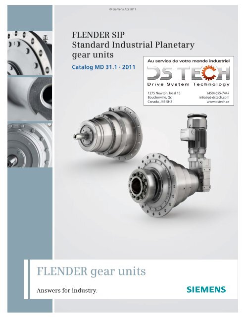
© Siemens AG 2011<strong>FLENDER</strong> SIPStandard Industrial Planetary<strong>gear</strong> <strong>units</strong>Catalog MD 31.1 20111275 Newton, local 15Boucherville, Qc,Canada, J4B 5H2(450) 655-7447info@pt-dstech.comwww.dstech.ca<strong>FLENDER</strong> <strong>gear</strong> <strong>units</strong>Answers for industry.
© Siemens AG 2011Related catalogs<strong>FLENDER</strong> SIG MD 30.1Standard industrial <strong>gear</strong> unitPLANUREX 2 MD 20.3Planetary Gear UnitsE86060-K5730-A111-A1-7600E86060-K5720-A131-A2-6300<strong>FLENDER</strong> couplings MD 10.1Standard couplingsGirth Gear Units MD 20.4for Tube MillsE86060-K5710-A111-A4-7600E86060-K5720-A141-A1-7400ARPEX MD 10.5Composite CouplingsPaper Machine Drives MD 20.5E86060-K5710-A151-A2-7400E86060-K5720-A151-A1-6300ARPEX MD 10.9High Performance CouplingsConveyor Drives MD 20.6E86060-K5710-A191-A2-7400ARPEX MD 10.10Couplings MiniatureE86060-K5710-A211-A2-6300ARPEX MD 10.11Torque LimitersE86060-K5720-A161-A2-6300Marine Reduction Gearboxes MD 20.7E86060-K5720-A171-A1-7400Products for Automation and Drives CA 01Interactive catalog(450) 655-7447info@pt-dstech.comwww.dstech.caE86060-K5710-A221-A2-7400DVD:E86060-D4001-A510-D0-7600Gear Units MD 20.1Sizes 3–22MallInformation and ordering platformin the Internet:E86060-K5720-A111-A2-6300www.siemens.com/industrymallGear Units MD 20.11Sizes 23–28E86060-K5720-A211-A1-6300Bucket Elevator Drives MD 20.2E86060-K5720-A121-A2-63001275 Newton, local 15Boucherville, Qc,Canada, J4B 5H2
© Siemens AG 2011Answers for industry.Siemens Industry answers the challenges in the manufacturingand the process industry as well as in the building automation(450) 655-7447info@pt-dstech.comwww.dstech.cabusiness. Our drive and automation solutions based on TotallyIntegrated Automation (TIA) and Totally Integrated Power (TIP)are employed in all kinds of industry. In the manufacturingand the process industry. In industrial as well as in functionalbuildings.Siemens offers automation, drive, andlow-voltage switching technology aswell as industrial software from standardproducts up to entire industry solutions.The industry software enables ourindustry customers to optimize the entirevalue chain – from product designand development through manufactureand sales up to after-sales service. Ourelectrical and mechanical componentsoffer integrated technologies for the entiredrive train – from couplings to <strong>gear</strong><strong>units</strong>, from motors to control and drivesolutions for all engineering industries.Our technology platform TIP offersrobust solutions for power distribution.Check out the opportunities ourautomation and drive solutions provide.And discover how you can sustainablyenhance your competitive edge with us.1275 Newton, local 15Boucherville, Qc,Canada, J4B 5H2
Introduction© Siemens AG 20111Notes(450) 655-7447info@pt-dstech.comwww.dstech.ca1275 Newton, local 15Boucherville, Qc,Canada, J4B 5H21/4 Siemens MD 31.1 · 2011
© Siemens AG 2011Technical information22/2 Technical standards2/2 Shaft misalignment2/2 Mounting positions2/2 Environmental conditions2/2 Selection of oil2/2 Preservation2/2 Maintenance(450) 655-7447info@pt-dstech.comwww.dstech.ca1275 Newton, local 15Boucherville, Qc,Canada, J4B 5H2Siemens MD 31.1 · 2011
Technical information© Siemens AG 2011Shaft misalignment, mounting positions, environmentalconditions, selection of oil, preservation, maintenance■ OverviewTechnical standardsSelection of oil2The shafts are designed in accordance with DIN 743.The bearing service life is calculated in accordance withISO 281 taking into account the manufacturer's data.The <strong>gear</strong>ing is designed to be high-endurance in accordancewith ISO 6336.Shaft misalignmentShaft misalignment is the result of displacement during assemblyand operation and, where machines constructed with 2radial bearings each are rigidly coupled, will cause high loadsbeing placed on the bearings. Elastic deformation of baseframe, foundation and machine housing will lead to shaftmisalignment which cannot be prevented, even by precisealignment. Furthermore, because individual components of thedrive train heat up differently during operation, heat expansionof the machine housings causes shaft misalignment.Poorly aligned drives are often the cause of seal or rolling bearingfailure. Alignment should be carried out by specialist personnelin accordance with the Siemens operating instructions.Depending on the direction of the effective shaft misalignment adistinction is made between:<strong>FLENDER</strong> SIP <strong>gear</strong> <strong>units</strong> may be filled with oils from producersauthorized by Siemens AG, the oil producer or supplier beingresponsible for the quality of the product. For the selection of oilgrade and viscosity, the limits of application given in the tableare to be taken into consideration.A minimum operating viscosity of 25 cSt must be ensured.Viscosity ISO-VG at40 °C in mm 2 /s (cSt)Dip lubricationMinimum temperature limit in °C fordip lubricationMineral oilVG 220 -15 -25VG 320 -12 -25VG 460 -10 -25Synthetic oilIn the case of dip lubrication, all parts to be lubricated are lyingin the oil or are adequately splash lubricated.If the temperatures are below the values as listed in the table, theoil must be heated.In case of dip lubrication, the oil temperature must not dropbelow the pour point of the selected oil. Axial misalignmentRadial misalignmentIn the case of ambient temperatures outside the permissiblerange, you will need to contact us.Mineral oil of viscosity ISO-VG 220 is recommended asstandard. For input speeds < 900 rpm oil of viscosityISO-VG 460 is recommended in combination with a higheroil level.PreservationThe internal preservation of <strong>FLENDER</strong> SIP <strong>gear</strong> <strong>units</strong> isdependent on the oil used.(450) 655-7447info@pt-dstech.comwww.dstech.ca For <strong>gear</strong> <strong>units</strong> with corrosion prevention, the following storagetimes are possible:Angular misalignmentStandard preservationLong-term preservationUp to 6 months Up to 24 months 1)Up to 36 months 2)The expected shaft misalignment must be taken into account onselecting the connection between the components and the inputshaft or output shaft. Guidelines and limits for compensation ofshaft misalignment can be obtained from the manufacturer.If the storage periods mentioned are exceeded, the anticorrosiveagent in the <strong>gear</strong> unit is to be renewed.The externally protruding shaft ends and machined surfaces arealso preserved.Mounting positions<strong>FLENDER</strong> SIP <strong>gear</strong> <strong>units</strong> are available for horizontal installation.Other mounting positions are possible on request.Environmental conditions<strong>FLENDER</strong> SIP <strong>gear</strong> <strong>units</strong> are designed for operation in largehalls, as well as outdoors.MaintenanceCompliance with the conditions for operation and installation isessential. To prevent damage to the <strong>gear</strong> unit or failure of thedrive, regular inspection and maintenance must be performedas specified in the operating instructions.Explosive environments are excluded.The range of permissible ambient temperatures is:-20 °C ≤ t U ≤ 50 °C.1275 Newton, local 15Boucherville, Qc,Canada, J4B 5H21) Only if mineral oil or synthetic oil on PAO basis is used.2) Only if synthetic oil on PG basis is used.2/2 Siemens MD 31.1 · 2011
© Siemens AG 2011Selection of the <strong>gear</strong> <strong>units</strong>33/2 Guidelines for selection3/2 Constant mechanical power rating3/3 Variable power rating3/4 Key to symbols3/5 Calculation example3/6 Service factors3/8 Overview tables3/8 Actual ratio3/8 Nominal power ratings3/9 Nominal output torques3/9 Thermal capacities(450) 655-7447info@pt-dstech.comwww.dstech.ca1275 Newton, local 15Boucherville, Qc,Canada, J4B 5H2Siemens MD 31.1 · 2011
Selection of the <strong>gear</strong> <strong>units</strong>Guidelines for selection© Siemens AG 20113Constant mechanical power rating■ Overview1. Determination of <strong>gear</strong> unit type and size1.1 Find the transmission ration 1i s =n 21.2 Determine the nominal power rating of the <strong>gear</strong> unitP 2N ≥ P 2 f 1 f 2It is not necessary to consult Siemens, if:3.33P 2 ≥ P 2N1.3 Check for maximum torquee.g.: peak operating, starting or braking torque2. Determination of oil supply: Horizontal mounting positionAll parts to be lubricated are lying in the oil or are splashlubricated.3. Determination of required thermal capacity P GData required:•Gear unit size•Nominal ratio•Ambient temperatureFor the calculation below, the following has been assumed:•Gear unit with dip lubrication•Operating cycle per hour: 100 %•Installation in a large hall (wind velocity ≥ 1.4 m/s)•Gear unit with mineral oil ISO-VG220T A n 1P 2N = f 39550Gear unit sizes and number of reduction stages are given inrating tables depending on i N and P 2N .1.4 Check whether additional forces on the output shaftare permissible; it is essential to consult Siemens!1.5 Check whether the actual ratio i as per tables onPage 3/8 is acceptableDetermination of the thermal capacities:•Without auxiliary cooling P G = P GA x f 4If P G ≥ P 2 → <strong>gear</strong> unit with selected cooling is adequate.If P G < P 2 → it is necessary to consult Siemens.(450) 655-7447info@pt-dstech.comwww.dstech.ca1275 Newton, local 15Boucherville, Qc,Canada, J4B 5H23/2 Siemens MD 31.1 · 2011
© Siemens AG 2011Selection of the <strong>gear</strong> <strong>units</strong>Guidelines for selection■ OverviewFor driven machines with constant speeds and variable powerratings the <strong>gear</strong> unit can be designed according to the equivalentpower rating. For this a working cycle where phases I, II ...n require power P I , P II ... P n and the respective power ratingsoperate for time fractions X I , X II ...X n is taken as a basis. Theequivalent power rating can be calculated from these specificationswith the following formula:6.6 X I X IIP 2eq = P 6.6 + PI II6.6 + ... P 6.6n100 100The size of the <strong>gear</strong> unit can then be determined analogously topoints 1.1 ... 1.5 and 3.The following applies:X n100Variable power ratingIf any one of the three requirements is not met, P 2eq must berecalculated.It must be borne in mind that a brief peak power rating notincluded in the calculation of P 2eq must not be greater thanP max = 1.5 x P 2N .In applications where the torque is variable but the speedconstant, the <strong>gear</strong> unit can be designed on the basis of theso called equivalent torque.For specific applications, a <strong>gear</strong> unit design which is finite-lifefatigue-resistant can be sufficient. This includes, for example,sporadic operation (e.g. lockgate drives).Example: Service classification3P 2N ≥ P 2eq f 1 f 2PP 2eqThen, when P 2N has been determined, the power and timefractions must be checked by applying the following requirements:• The individual power fractions P I , P II … P n must be greaterthan 0.4 x P 2N .• The individual power fractions P I , P II ... P n must not exceed1.4 x P 2N .• If power fractions P I , P II ... P n are greater than P 2N , the sum oftime fractions X I , X II … X n must not exceed 10 %.X l=15%P lIP llP lll PlVII III IVX lI=30% X lII=40%X=100%G_MD30_EN_00043XX lV=15%1275 Newton, local 15Boucherville, Qc,Canada, J4B 5H2In the case of a service classification, it is necessary toconsult Siemens.(450) 655-7447info@pt-dstech.comwww.dstech.caSiemens MD 31.1 · 20113/3
Selection of the <strong>gear</strong> <strong>units</strong>Guidelines for selection© Siemens AG 20113Key to symbols■ OverviewKey to symbolsDescription Explanation Chapter/PageE D Operating cycle per hour in %(e. g. E D = 80 % per hour)f 1 Factor for driven machine 3/6f 2 Factor for prime mover 3/7f 3 Peak torque factor 3/7f 4 Thermal factor 3/7i Actual ratio 3/8i Ni sNominal ratioRequired ration 1 Input speed (rpm) 3/2n 2 Output speed (rpm) 3/2P G Required thermal capacity (kW) 3/2P GA Thermal capacity (kW) for <strong>gear</strong> <strong>units</strong> without auxiliary cooling 3/9P 2N Nominal power rating of <strong>gear</strong> unit (kW), see rating tables 3/8P req.Notes and legend for tables of thermal capacitiesDimensions in mmWeights in kgOil quantities in liters (l)Fits to DIN/ISO 286-2Required power rating (kW)P 2 Power rating of driven machine (kW) 3/2t UAmbient temperature (°C)T A Max. torque occurring on input shaft, e.g.: peak operating, starting or braking torque (Nm) 3/2T 2N Nominal output torque (kNm) 3/9T 2Torque (Nm) of the driven machineP 2eq Equivalent power rating (kW) 3/3P I , P II , P n Fractions of power rating (kW) obtained from service classification 3/3X I , X II , X n Fractions of time (%) obtained from service classification 3/3fT 2reqLine frequency (Hz)Required design torquei minSIP Minimum ratio of planetary <strong>gear</strong> unit 5/2i maxSIP Maximum ratio of planetary <strong>gear</strong> unit 5/2n minGM Minimum output speed of the <strong>gear</strong>ed motor 5/2n maxGM Maximum output speed of the <strong>gear</strong>ed motor 5/2n GMOutput speed of the <strong>gear</strong>ed motori actSIP Actual ratio of planetary <strong>gear</strong> unit 5/3f max Maximum factor – maximum permissible overload of the drive 5/3f Bk Breakdown factor of the electric motor 5/3f St Starting factor of the electric motor 5/3f SactSIP Actual service factor of the selected planetary <strong>gear</strong> unit 5/33/5, 3/9(450) 655-7447info@pt-dstech.comwww.dstech.ca1275 Newton, local 15Boucherville, Qc,Canada, J4B 5H23/4 Siemens MD 31.1 · 2011
© Siemens AG 2011Selection of the <strong>gear</strong> <strong>units</strong>Guidelines for selection■ OverviewKnown criteria for the calculation examplePrime mover:• Electric motor, 6-pole:• Motor speed:• Max. starting torque:P 1 = 55 kWn 1 = 1000 rpmT A = 1332.5 NmDriven machine:• Section mill:P 2 = 45 kW• Speed:n 2 = 32 rpm• Duty:24 h/day• Starts per hour: 15• Operating cycle per hour: E D = 40 %• Ambient temperature: t U = 50 °C• Installation in a large hallGear unit design:• Planetary <strong>gear</strong> unit• Mounting position:• Output shaft d 2 :• Direction of rotation ofoutput shaft d 2 :horizontalHollow shaft with shrink diskcounterclockwise, whenviewing the shaft end faceThe influence of additional forces on the shaft ends mustbe taken into account.Required:•Type of <strong>gear</strong> unit•Gear unit size1. Determination of <strong>gear</strong> unit type and size1.1 Find the transmission ration 1i s = =n 21000 rpm32 rpmCalculation example1.2 Determine the nominal power rating of the <strong>gear</strong> unitFrom table, see Page 3/8 (nominal power rating P 2N ) <strong>gear</strong> <strong>units</strong>ize <strong>FLENDER</strong> SIP 45 with P 2N = 127 kW selected.1.3 Check the maximum loadingNo load stage exceeds the permissible maximum loading.1.4 Check for over dimensioning= 31.25 → i N = 30 selectedP 2N ≥ P 2 f 1 f 2 = 45 kW 2.5 1 = 112.5 kWP max = 45 kW < 1.5127 kW = 190.5 kW3.33 P 2 ≥ P 2N 3.33 45 kW = 149.85 kW > P 2N3It is not necessary to consult Siemens.1.5 Check the starting torque1275 Newton, local 15Boucherville, Qc,Canada, J4B 5H2T A n 1P 2N ≥ f 3 =9550P 2N = 127 kW < 175.8 kW1332.5 Nm 1000 rpm9550It is necessary to limit the motor torque on starting.1.26 = 175.8 kW1.6 Check the thermal capacity P GCheck whether P G ≥ P 2P G = P GA f 4 = 42 kW 0.74 = 31.08 kWDue to insufficient thermal capacity, another <strong>gear</strong> unit size, in thiscase <strong>FLENDER</strong> SIP 55, must be selected with:P G = 63 kW:P G = P GA f 4 = 63 kW 0.74 = 46.62 kWThere will then be no need to limit the starting torque of the motor,because the following applies for the selected <strong>gear</strong> unit size:P 2N = 236 kW > 175.8 kW(450) 655-7447info@pt-dstech.comwww.dstech.caSiemens MD 31.1 · 20113/5
Selection of the <strong>gear</strong> <strong>units</strong>Guidelines for selection© Siemens AG 2011Service factors■ OverviewFactor for driven machines f 13Driven machinesEffective operating period underload in hours≤ 0.5 > 0.5 – 10 > 10Waste water treatment•Thickeners(central drive) – – 1.2•Filter presses 1.0 1.3 1.5•Flocculation apparatus 0.8 1.0 1.3•Aerators – 1.8 2.0•Raking equipment 1.0 1.2 1.3•Combined longitudinal and rotary 1.0 1.3 1.5rakes•Pre-thickeners – 1.1 1.3•Screw pumps – 1.3 1.5•Water turbines – – 2.0Pumps•Centrifugal pumps 1.0 1.2 1.3•Positive-displacement pumps-1 piston 1.3 1.4 1.8-> 1 piston 1.2 1.4 1.5Dredgers•Bucket conveyors – 1.6 1.6•Dumping devices – 1.3 1.5•Caterpillar traveling <strong>gear</strong>s 1.2 1.6 1.8Bucket wheel excavators-as pick-up – 1.7 1.7-for primitive material – 2.2 2.2•Cutter heads – 2.2 2.2•Slewing <strong>gear</strong>s 1) – 1.4 1.8Plate bending machines 1) – 1.0 1.0Chemical Industry•Extruders – – 1.6•Dough mills – 1.8 1.8•Rubber calenders – 1.5 1.5•Cooling drums – 1.3 1.4Mixers for-uniform media 1.0 1.3 1.4-non-uniform media 1.4 1.6 1.7Agitators for media with-uniform density 1.0 1.3 1.5-non-uniform density 1.2 1.4 1.6-non-uniform gas absorption 1.4 1.6 1.8•Toasters 1.0 1.3 1.5•Centrifuges 1.0 1.2 1.3Metal working mills•Plate tilters 1.0 1.0 1.2•Ingot pushers 1.0 1.2 1.2•Winding machines – 1.6 1.6•Cooling bed transfer frames – 1.5 1.5•Roller straighteners – 1.6 1.6Roller tables-continuous – 1.5 1.5-intermittent – 2.0 2.0•Reversing tube mills – 1.8 1.8Shears-continuous 1) – 1.5 1.5-crank type 1) 1.0 1.0 1.0•Continuous casting drivers 1) – 1.4 1.4Design for power rating of driven machine P 2 :1) Designed power corresponding to max. torque2) Load can be exactly classified, for instance, according to FEM 10013) A check for thermal capacity is absolutely essentialDriven machinesEffective operating periodunder load in hours≤ 0.5 > 0.5 – 10 > 10Rolls-Reversing blooming mills – 2.5 2.5-Reversing slabbing mills – 2.5 2.5-Reversing wire mills – 1.8 1.8-Reversing sheet mills – 2.0 2.0-Reversing plate mills – 1.8 1.8•Roll adjustment drives 0.9 1.0 –Conveyors•Bucket conveyors – 1.4 1.5•Hauling winches 1.4 1.6 1.6•Hoists – 1.5 1.8•Belt conveyors ≤ 150 kW 1.0 1.2 1.3•Belt conveyors ≥ 150 kW 1.1 1.3 1.4•Goods lifts 1) – 1.2 1.5•Passenger lifts 1) – 1.5 1.8•Apron conveyors – 1.2 1.5•Escalators 1.0 1.2 1.4•Railway vehicles – 1.5 –Frequency converters – 1.8 2.0Reciprocating compressors – 1.8 1.9Cranes 2)•Slewing <strong>gear</strong>s 1) 1.0 1.4 1.8•Luffing <strong>gear</strong>s 1.0 1.1 1.4•Traveling <strong>gear</strong>s 1.1 1.6 2.0•Hoisting <strong>gear</strong>s 1.0 1.1 1.4•Derricking jib cranes 1.0 1.2 1.6Cooling towers•Cooling tower fans – – 2.0•Blowers(axial and radial) – 1.4 1.5Food industryCane sugar production•Cane knives 1) – – 1.7•Cane mills – – 1.7Beet sugar production•Beet cossettes macerators – – 1.2•Extraction plants, mechanicalrefrigerators, cooking appliances– – 1.4•Beet washers, beet cutters – – 1.5Paper machines•of all kinds 3) – 1.8 2.0•Pulper drives (on request)Centrifugal compressors – 1.4 1.5Cableways•Material ropeways – 1.3 1.4•To-and-fro system aerial ropeways – 1.6 1.8•T-bar lifts – 1.3 1.4•Continuous ropeways – 1.4 1.6Cement industry•Concrete mixers – 1.5 1.5•Breakers 1) – 1.2 1.4•Rotary kilns – – 2.0•Tube mills – – 2.0•Separators – 1.6 1.6•Roll crushers – – 2.0Note: The listed load parameters are empirical values.Prerequisite for their application is that the machinery andequipment mentioned correspond to generally accepted designand load specifications. In case of deviations from standardconditions, please contact us. For driven machines which arenot listed in this table, please refer to us.(450) 655-7447info@pt-dstech.comwww.dstech.ca1275 Newton, local 15Boucherville, Qc,Canada, J4B 5H23/6 Siemens MD 31.1 · 2011
© Siemens AG 2011Selection of the <strong>gear</strong> <strong>units</strong>Guidelines for selectionService factors■ Overview (continued)Factor for prime mover f 2 Peak torque factor f 3Machine Factor for prime mover f 2Electric motors, hydraulic motors,turbinesPiston engines 4 – 6 cylinders,cyclic variation 1 : 100 to 1 : 200Piston engines 1 – 3 cylinderscyclic variation 1 : 1001.01.251.5Direction of load Peak torque factor f 3Load peaks per hour1 – 5 6 – 30 31 – 100 > 100Steady direction of load 0.67 0.86 0.93 1.13Alternating direction of load 0.93 1.26 1.46 1.66Thermal factor f 4(Gear <strong>units</strong> without auxiliary cooling or with fan)Ambient temperature t U Operating cycle per hour (E D )in °C in %100 80 60 40 2010 1.14 1.20 1.32 1.54 2.0420 1.00 1.06 1.16 1.35 1.7930 0.87 0.93 1.00 1.18 1.5640 0.71 0.75 0.82 0.96 1.2750 0.55 0.58 0.64 0.74 0.983(450) 655-7447info@pt-dstech.comwww.dstech.ca1275 Newton, local 15Boucherville, Qc,Canada, J4B 5H2Siemens MD 31.1 · 20113/7
© Siemens AG 2011Selection of the <strong>gear</strong> <strong>units</strong>Overview tablesNominal output torques T 2N (kNm)Thermal capacity P GA (kW) n 1 = 1500 rpm■ Technical data (continued)Nominal output torques T 2N (kNm)Nominal ratio Gear unit sizesi N 30 35 37 40 45 50 55 6025 10 15 20 25 35 45 65 8027 10 15 20 25 35 45 65 8030 10 15 20 25 35 45 65 8033.5 10 15 20 25 35 45 65 8038 10 15 20 25 35 45 65 8045 10 15 20 25 35 45 65 803Thermal capacity P GA (kW) n 1 = 1500 rpmNominal ratio Gear unit sizesi N 30 35 37 40 45 50 55 6025 13 20 26 32 42 52 63 7327 13 20 26 32 42 52 63 7330 13 20 26 32 42 52 63 7333.5 13 20 26 32 42 52 63 7338 13 20 26 32 42 52 63 7345 13 20 26 32 42 52 63 731275 Newton, local 15Boucherville, Qc,Canada, J4B 5H2The values are applicable for:• Operating cycle per hour: 100 %,• Installation in a large hall,• Up to 1000 m above sea level,• Ambient temperature t U = 20 °C(450) 655-7447info@pt-dstech.comwww.dstech.caSiemens MD 31.1 · 20113/9
Selection of the <strong>gear</strong> <strong>units</strong>© Siemens AG 2011Notes3(450) 655-7447info@pt-dstech.comwww.dstech.ca1275 Newton, local 15Boucherville, Qc,Canada, J4B 5H23/10 Siemens MD 31.1 · 2011
© Siemens AG 2011Flange-mounted <strong>gear</strong> <strong>units</strong>horizontal mounting position44/2 Selection and ordering dataGear unit dimensions4/2 Two-stage <strong>gear</strong> <strong>units</strong>, coaxial(450) 655-7447info@pt-dstech.comwww.dstech.ca1275 Newton, local 15Boucherville, Qc,Canada, J4B 5H2Siemens MD 31.1 · 2011
© Siemens AG 2011Flange-mounted <strong>gear</strong> <strong>units</strong> horizontal mounting positionGear unit dimensionsTwo-stage <strong>gear</strong> <strong>units</strong>, coaxial■ Selection and ordering datal 1 Shrink diskClient shaftczØ d4Ø daØ d3Ø d2G 1 G 2Ø kØ d14l 3l 2G_MD30_EN_00107Ø stn x t(=360°)O2RCGear <strong>units</strong>izesOutputDimensions in mmDrive endshaft endFlangeØ d 11) I 1 c Ø d a Ø d 4 f7 G 1 G 2 Ø k z Ø s n t30 40 70 17 375 290 354 133 335 8 17.5 16 22.5°35 40 70 17 425 340 373 138 385 8 17.5 20 18°37 45 80 19 450 370 393 149 410 8 17.5 24 15°40 45 80 19 480 390 399 152 435 8 22 18 20°45 50 100 19 540 445 428 166 490 8 22 20 18°50 50 100 24 585 495 450 167 540 8 22 24 15°55 60 110 29 650 535 516 185 595 8 26 24 15°60 60 110 34 695 585 535 207 640 8 26 24 15°Data position of the Order No. 1 to 6 7 8 9 10 11 12 13 14 15 16Order No.: 2LP069 0 - 0 E ■ . 0 - 0 . . 0Gear <strong>units</strong>izesChamferon d 2Dimensions in mmShaft of driven machineØ d 2 h6 2) Ø d 3 h6 2) l 2 l 3 l kgOil quantity Weight 3) For order No. supplement for11th, 14th and 15th position,see Pages 4/4 to 4/530 1 x 45° 90 88 60 60 1.80 100 A35 1 x 45° 100 98 64 64 2.00 130 B37 1 x 45° 110 108 68 68 2.70 167 C40 1 x 45° 120 118 76 76 3.00 186 D45 2.5 x 45° 130 125 80 80 4.80 268 E50 2.5 x 45° 140 135 82 82 5.50 331 F55 2.5 x 45° 165 160 96 96 8.00 480 G60 2.5 x 45° 180 175 116 100 8.40 576 H1)Shaft diameter d 1 < 100 ➝ tolerance m6For shaft end d 1 with parallel key in accordance with DIN 6885-1and central holes, see Page 6/2.2) > 160 g63) Weight with shrink disk and without oil.(450) 655-7447info@pt-dstech.comwww.dstech.ca1275 Newton, local 15Boucherville, Qc,Canada, J4B 5H24/2 Siemens MD 31.1 · 2011
© Siemens AG 2011Flange-mounted <strong>gear</strong> <strong>units</strong> horizontal mounting position■ Selection and ordering data (continued)Gear unit dimensionsTwo-stage <strong>gear</strong> <strong>units</strong>, coaxialG 1G 2zl 1l 2Hollow shaft with splinescGearbox shaft d1DIN 5480d4 da d2R4b 1b 2G_MD30_EN_00106stn x t(=360°) k1275 Newton, local 15Boucherville, Qc,Canada, J4B 5H2(450) 655-7447info@pt-dstech.comwww.dstech.caO2RCGear <strong>units</strong>izesOutputDimensions in mmDrive endshaft endFlangeØ d 11) I 1 c Ø d a Ø d 4 f7 G 1 G 2 Ø k z Ø s n t30 40 70 17 375 290 354 84 335 8 17.5 16 22.5°35 40 70 17 425 340 373 82 385 8 17.5 20 18°37 45 80 19 450 370 393 101 410 8 17.5 24 15°40 45 80 19 480 390 399 104 435 8 22 18 20°45 50 100 19 540 445 428 117 490 8 22 20 18°50 50 100 24 585 495 450 114 540 8 22 24 15°55 60 110 29 650 535 516 130 595 8 26 24 15°60 60 110 34 695 585 535 136 640 8 26 24 15°Data position of the Order No. 1 to 6 7 8 9 10 11 12 13 14 15 16Order No. 2LP069 1 - 0 E ■ - 0 - 0 - - 0Gear <strong>units</strong>izesDimensions in mmShaft of driven machineOilquantityØ d 2 h6 2) I 2 b 1 b 2 R l kgWeight 3)Shaft of driven machinewith splines in accordancewith DIN 548030 92 81 55 20 1.5 1.80 93 W 90 x 3 x 28 x 8f A35 102 86 60 20 1.5 2.00 118 W 100 x 3 x 32 x 8f B37 112 102 70 25 1.5 2.70 153 W 110 x 3 x 35 x 8f C40 122 107 75 25 1.5 3.00 166 W 120 x 3 x 38 x 8f D45 132 118 80 30 2.5 4.80 242 W 130 x 5 x 24 x 8f E50 142 123 85 30 2.5 5.50 303 W 140 x 5 x 26 x 8f F55 172 144 100 35 2.5 8.00 438 W 170 x 5 x 32 x 8f G60 182 155 110 35 2.5 8.40 516 W 180 x 5 x 34 x 8f H1)Shaft diameter d 1 < 100 ➝ tolerance m6For shaft extension d 1 with parallel key in accordance with DIN 6885-1and central holes, see Page 6/2.2) > 160 g63) Weight without oil.For order No. supplement for11th, 14th and 15th position,see Pages 4/4 to 4/5Siemens MD 31.1 · 20114/3
© Siemens AG 2011Flange-mounted <strong>gear</strong> <strong>units</strong> horizontal mounting positionTwo-stage <strong>gear</strong> <strong>units</strong>, coaxial4■ Selection and ordering data (continued)Order No. supplement 7th, 10th, 11th and 14th positionOutput shaft designData position of the Order No. 1 to 6 7 8 9 10 11 12 13 14 15 16Order No. 2LP069 ■ - 0 E ■ ■ 0 - 0 ■ . 0Hollow shaft for shrink disk 0Hollow shaft with splines in accordance with DIN 5480 1Gear unit size30 A35 B37 C40 D45 E50 F55 G60 HSealingSeal oninput shaftSeal onoutput shaftWDR WDR 0WDR Taconite 1Taconite WDR 2Taconite Taconite 3Nominal <strong>gear</strong> ratio i N25 A27 B30 C33.5 D38 E45 F(450) 655-7447info@pt-dstech.comwww.dstech.ca1275 Newton, local 15Boucherville, Qc,Canada, J4B 5H24/4 Siemens MD 31.1 · 2011
© Siemens AG 2011Flange-mounted <strong>gear</strong> <strong>units</strong> horizontal mounting positionTwo-stage <strong>gear</strong> <strong>units</strong>, coaxial1275 Newton, local 15Boucherville, Qc,Canada, J4B 5H2(450) 655-7447info@pt-dstech.comwww.dstech.ca■ Selection and ordering data (continued)Order No. supplement, 15th positionFor motor size Motor power Rated speed Data position of the Order No. 1 to 6 7 8 9 10 11 12 13 14 15 16 Order codeP Mn MkWrpmOrder No. 2LP069 . - 0 E . . 0 - 0 . ■ 0 ...4-pole, 50 HzIEC 63M 0.18 1395 A –IEC 71M 0.37 1384 B –IEC 80M 0.75 1399 C –IEC 90S 1.1 1440 D –IEC 90L 1.5 1440 E –IEC 100L 3 1420 F –IEC 112M 4 1440 G –IEC 132S 5.5 1455 H –IEC 132M 7.5 1455 J –IEC 160M 11 1460 K –IEC 160L 15 1460 L –IEC 180M 18.5 1465 M –IEC 180L 22 1465 N –IEC 200L 30 1465 P –IEC 225S 37 1475 Q –IEC 225M 45 1475 R –IEC 250M 55 1480 S –IEC 280S 75 1485 T –IEC 280M 90 1485 U –IEC 315S 110 1488 V –IEC 315M 132 1488 W –4-pole, 60 HzIEC 63M 0.21 1705 Z Q1AIEC 71M 0.43 1725 Z Q1BIEC 80M 0.86 1725 Z Q1CIEC 90S 1.3 1755 Z Q1DIEC 90L 1.75 1775 Z Q1EIEC 100L 3.45 1704 Z Q1FIEC 112M 4.6 1728 Z Q1GIEC 132S 6.3 1746 Z Q1HIEC 132M 8.6 1746 Z Q1JIEC 160M 12.6 1752 Z Q1KIEC 160L 17.3 1752 Z Q1LIEC 180M 21.3 1758 Z Q1MIEC 180L 25.3 1758 Z Q1NIEC 200L 34.5 1758 Z Q1PIEC 225S 42.5 1770 Z Q1QIEC 225M 52 1770 Z Q1RIEC 250M 63 1776 Z Q1SIEC 280S 86 1782 Z Q1TIEC 280M 104 1782 Z Q1UIEC 315S 127 1786 Z Q1VIEC 315M 152 1786 Z Q1WOther motor Y23 1) Y20 1) Z Q1Y41) In addition to order code Y23 and Y20, plain text is required for P M or n M .Siemens MD 31.1 · 20114/5
© Siemens AG 2011Flange-mounted <strong>gear</strong> <strong>units</strong> horizontal mounting positionNotes4(450) 655-7447info@pt-dstech.comwww.dstech.ca1275 Newton, local 15Boucherville, Qc,Canada, J4B 5H24/6 Siemens MD 31.1 · 2011
© Siemens AG 2011Gear unit combinations55/2 <strong>FLENDER</strong> SIP with MOTOX-N5/2 Overview5/2 Benefits5/2 Design5/2 Configuration5/4 Dimensioned drawings5/5 Selection and ordering data(450) 655-7447info@pt-dstech.comwww.dstech.ca1275 Newton, local 15Boucherville, Qc,Canada, J4B 5H2Siemens MD 31.1 · 2011
Gear unit combinations© Siemens AG 2011Gear unit combinations<strong>FLENDER</strong> SIP with MOTOX-N■ OverviewThe planetary <strong>gear</strong> <strong>units</strong> of the <strong>FLENDER</strong> SIP series can becombined with parallel shaft and bevel helical <strong>gear</strong>ed motors ofthe MOTOX-N series.■ Benefits7 Combination of the two series as standard7 Large selection of motors, such as asynchronous and servomotors7 Large range of ratios7 Orthogonal as well as parallel arrangement7 Utilization of the MOTOX-N product spectrum in the context ofthe Siemens DriveTrain7 Utilization of options, such as brakes, encoders and sensors■ ConfigurationDesign example for belt conveyorPrime mover:•Electric motor, 4-pole: P 1 = 3 kW•Line frequency: f = 50 HzDriven machine:•Speed: n 2 = 0.9 rpm• Service factor: f 1 = Page 3/6Gear unit design:•Mounting position: Horizontal•Shaft arrangement: Orthogonal1. Determination of the SIP <strong>gear</strong> unit sizeKAF..P 1 9550 3 kW 9550T 2 ==n 2 0.9 rpmT 2 = 31833.4 Nm5T 2req = T 2 f 1 = 31833.4 Nm 1.402..G_MD30_XX_00102T 2req = 44566.7 NmT 2N ≥ T 2req45000 Nm ≥ 44566.7 NmSelected <strong>gear</strong> unit size from selection table on Page 3/9:<strong>FLENDER</strong> SIP 50.(450) 655-7447info@pt-dstech.comwww.dstech.caF..AF..O2.. – <strong>FLENDER</strong> SIP planetary <strong>gear</strong> unitKAF.. – Bevel helical <strong>gear</strong>ed motor MOTOX-NF..AF.. – Parallel shaft <strong>gear</strong>ed motor MOTOX-N2. Determination of the associated <strong>gear</strong>ed motor2.1 Calculation of the valuesn minGM = n 2 i minSIP = 0.9 rpm 25n minGM = 22.5 rpm■ DesignStandard assignmentO2.. KAF../F..AF.. Nominal sizeflange<strong>gear</strong>ed motor30 48 A200 4035 48 A200 4037 68 A250 4540 68 A250 4545 88 A300 5050 88 A300 5055 108 A350 6060 108 A350 60Nominal diameter ofhollow shaft<strong>gear</strong>ed motorThe <strong>gear</strong> <strong>units</strong> of the MOTOX-N series must be the flangemountedversion with hollow shaft and parallel keyway.n maxGM = n 2 i maxSIP = 0.9 rpm 45n maxGM = 40.5 rpmPossible speed range for <strong>gear</strong>ed motor: 22.5 rpm… 40.5 rpmValues for selecting the <strong>gear</strong>ed motor:•Electric motor, 4-pole: P 1 = 3 kW•Line frequency: f = 50 Hz•Output speed: n GM = 22.5 rpm… 40.5 rpm•Service factor: f 1 ≥ 1.41275 Newton, local 15Boucherville, Qc,Canada, J4B 5H25/2 Siemens MD 31.1 · 2011
© Siemens AG 2011Gear unit combinationsGear unit combinations<strong>FLENDER</strong> SIP with MOTOX-N■ Configuration (continued)2.2 Selection of the <strong>gear</strong>ed motorSet filter in accordance with the actual values and select <strong>gear</strong>edmotor with regard to the shaft arrangement.Note: The standard assignment as shown in the table onPage 5/2 must be complied with. Other combinations areavailable on request.The thermal capacity of the <strong>gear</strong>ed motor must be checked.Selection: KAF 88Possible speeds for MOTOX-N: 35, 29, 252.3 Selection of speed of the <strong>gear</strong>ed motorFor table, see Page 3/8.Due to the wide variety of possible speeds for MOTOX-N, theuse of a matrix is recommended for the purposes of comparingall the combinations.Outputspeed of<strong>gear</strong>edmotor n GMn GMn 2 =i actSIPActual ratio i planetary <strong>gear</strong> unit i istSIP25.07 27.26 30.00 33.52 38.22 44.8035 1.40 1.28 1.17 1.04 0.92 0.7829 1.16 1.06 0.97 0.87 0.76 0.6525 1.00 0.92 0.83 0.75 0.65 0.56f max =f SactSIP =f SactSIPThe breakdown torque or starting torque of the electric motormust therefore be limited to maximum 2.1 times, using afrequency converter for example.2.5 Configuration of <strong>gear</strong>ed motor with mandatory selectionof options:1. Flange mounting type – design FAF.. or K..AF..2. Output shaft type – hollow shaftf 3f SactSIP = 1.41f max =1.410.672.1 ≤ 3.9T 2NT 2f 3 see Page 3/7= 2.145000 Nm=31833.4 Nm3. Diameter of output shaft – to match d 1 on Page 4/2 or 4/351275 Newton, local 15Boucherville, Qc,Canada, J4B 5H2Selected <strong>gear</strong>ed motor:• K88-LA100ZLD4E with:- P 1 = 3 kW- n GM = 35 rpm2.4 Check for overloadThe peak loads resulting from the starting procedure must notexceed the maximum factor for the <strong>gear</strong> unit combination f max .If this is the case, it is important to implement appropriate limitingusing a frequency converter, or similar.The peak factors f Bk /f St must be taken from the associated motordata sheet of Catalog D 87.1 MOTOX Geared Motors.The highest value must be used in each case.f max ≥ f Bk or f St(450) 655-7447info@pt-dstech.comwww.dstech.caSiemens MD 31.1 · 20115/3
Gear unit combinations© Siemens AG 2011Gear unit combinations<strong>FLENDER</strong> SIP with MOTOX-N■ Dimensioned drawingsl 5l 1a2a2aa4G_MD30_XX_001055l 3l 3al 1Data position of the Order 1 to 6 7 8 9 10 11 12 13 14 15 16Order No.: 2LP069 . - 0 F ■ . 0 - . . A .O2RR KAF..size Dimensions in mm For order No. supplement for 7th, 11th, 13th,14th and 16th position, see Pages 5/5 to 5/6Gear unit sizes SIP KAF..l 1 a a 2 a 4 l 330 48 332 432 78 186 520 A35 48 351 451 78 186 539 B37 68 373 486 89 220 593 C40 68 379 492 89 220 599 D45 88 394 536 110 262 671 E50 88 416 558 110 262 693 F55 108 483 639 136 328 799 G60 108 502 658 136 328 818 H(450) 655-7447info@pt-dstech.comwww.dstech.caData position of the Order 1 to 6 7 8 9 10 11 12 13 14 15 16Order No.: 2LP069 . - 0 F ■ . 1 - . . A .O2RP F..AF..size Dimensions in mm For order No. supplement for 7th, 11th, 13th,14th and 16th position, see Pages 5/5 to 5/6Gear unit sizes SIP F..AF..l 1 a a 2 l 3 l 530 48 332 150 93 533 491 A35 48 351 150 93 552 510 B37 68 373 180 111 606 551 C40 68 379 180 111 612 557 D45 88 394 230 132 683 621 E50 88 416 230 132 706 643 F55 108 483 280 160 805 739 G60 108 502 280 160 824 758 HThe motor dimensions can be found in Catalog D 87.1, MOTOX Geared Motors. The overall dimensions of the SIP MOTOX-Ncombination are obtained on the basis of these values.1275 Newton, local 15Boucherville, Qc,Canada, J4B 5H25/4 Siemens MD 31.1 · 2011
© Siemens AG 2011Gear unit combinations1275 Newton, local 15Boucherville, Qc,Canada, J4B 5H2(450) 655-7447info@pt-dstech.comwww.dstech.ca■ Selection and ordering dataOrder No. supplement 7th, 11th, 12th and 14th positionOrder No. supplement 13th and 16th position for <strong>FLENDER</strong> SIP O2RR with intermediate <strong>gear</strong> KAFGear unit combinations<strong>FLENDER</strong> SIP with MOTOX-NData position of the Order No. 1 to 6 7 8 9 10 11 12 13 14 15 16Order No. 2LP069 ■ - 0 F . ■ ■ - . ■ A .Output shaft designHollow shaft for shrink disk 0Hollow shaft with splines in accordance with DIN 5480 1SealingSeal on input shaftSeal on output shaftWDR WDR 0WDR Taconite 1TypeO2RR (<strong>FLENDER</strong> SIP O2RR with intermediate <strong>gear</strong> KAF.., shaft arrangement d 1 to d 2 : orthogonal) 0O2RP (<strong>FLENDER</strong> SIP O2RP with intermediate <strong>gear</strong> F..AF.., shaft arrangement d 1 to d 2 : parallel) 1Nominal <strong>gear</strong> ratio i N25 A27 B30 C33.5 D38 E45 FData position of the1 to 6 7 8 9 10 11 12 13 14 15 16Order No.Order No. 2LP069 . - 0 F . . 0 - ■ . A ■Ratio of intermediate <strong>gear</strong>SIP O2RR <strong>gear</strong> unit sizes30 35 37 40 45 50 55 607.22 7.22 5.36 5.36 5.54 5.54 7.68 7.68 0 08.40 8.40 6.44 6.44 6.69 6.69 9.36 9.36 0 19.32 9.32 7.58 7.58 8.03 8.03 10.97 10.97 0 210.15 10.15 8.50 8.50 9.41 9.41 12.90 12.90 0 311.35 11.35 9.52 9.52 11.21 11.21 13.74 13.74 0 411.95 11.95 10.40 10.40 11.64 11.64 16.75 16.75 0 513.90 13.90 11.41 11.41 14.04 14.04 19.63 19.63 0 615.42 15.42 11.94 11.94 16.85 16.85 23.08 23.08 0 716.79 16.79 14.35 14.35 19.75 19.75 26.48 26.48 0 818.78 18.78 16.89 16.89 23.54 23.54 31.25 31.25 1 020.54 20.54 18.93 18.93 25.53 25.53 33.87 33.87 1 122.54 22.54 21.22 21.22 28.50 28.50 36.44 36.44 1 224.85 24.85 23.16 23.16 30.87 30.87 44.44 44.44 1 327.55 27.55 25.42 25.42 34.40 34.40 52.08 52.08 1 428.90 28.90 27.99 27.99 41.50 41.50 61.22 61.22 1 533.60 33.60 30.38 30.38 49.80 49.80 70.24 70.24 1 637.28 37.28 32.78 32.78 58.37 58.37 82.90 82.90 1 740.60 40.60 39.39 39.39 69.57 69.57 89.85 89.85 1 845.41 45.41 46.37 46.37 75.45 75.45 99.90 99.90 2 049.65 49.65 51.96 51.96 84.21 84.21 108.52 108.52 2 154.49 54.49 58.23 58.23 91.22 91.22 120.03 120.03 2 260.08 60.08 63.57 63.57 103.38 103.38 128.86 128.86 2 366.60 66.60 69.78 69.78 111.37 111.37 138.87 138.87 2 475.45 75.45 76.84 76.84 120.42 120.42 150.31 150.31 2 583.25 83.25 83.40 83.40 130.77 130.77 163.51 163.51 2 694.12 94.12 90.89 90.89 144.58 144.58 178.90 178.90 2 7107.47 107.47 99.55 99.55 156.63 156.63 201.11 201.11 2 8122.19 122.19 109.64 109.64 176.50 176.50 219.64 219.64 2 0130.78 130.78 126.09 126.09 193.24 193.24 243.47 243.47 3 1150.76 150.76 136.60 136.60 215.25 215.25 278.10 278.10 3 2169.53 169.53 150.98 150.98 246.13 246.13 307.24 307.24 3 3176.14 176.14 272.95 272.95 3 4196.07 196.07 302.68 302.68 3 5215.68 215.68 3 6243.72 243.72 3 75Siemens MD 31.1 · 20115/5
Gear unit combinations© Siemens AG 20115Gear unit combinations<strong>FLENDER</strong> SIP with MOTOX-N■ Selection and ordering data (continued)Order No. supplement 13th and 16th position for <strong>FLENDER</strong> SIP O2RP with intermediate <strong>gear</strong> F.AFData position of the1 to 6 7 8 9 10 11 12 13 14 15 16Order No.Order No. 2LP069 . - 0 F . . 1 - ■ . A ■Ratio of intermediate <strong>gear</strong>SIP O2RP <strong>gear</strong> unit sizes30 35 37 40 45 50 55 604.33 4.33 3.97 3.97 4.77 4.77 5.68 5.68 0 05.20 5.20 4.49 4.49 5.82 5.82 6.60 6.60 0 16.12 6.12 5.75 5.75 6.82 6.82 7.32 7.32 0 26.86 6.86 6.74 6.74 8.01 8.01 8.70 8.70 0 37.68 7.68 8.03 8.03 9.19 9.19 10.04 10.04 0 48.39 8.39 8.55 8.55 10.71 10.71 10.98 10.98 0 59.23 9.23 10.31 10.31 13.07 13.07 12.77 12.77 0 611.09 11.09 12.38 12.38 15.31 15.31 14.16 14.16 0 713.05 13.05 14.51 14.51 18.00 18.00 16.82 16.82 0 814.63 14.63 17.29 17.29 20.65 20.65 19.41 19.41 1 016.39 16.39 18.75 18.75 24.38 24.38 22.81 22.81 1 117.89 17.89 20.93 20.93 26.42 26.42 25.85 25.85 1 219.64 19.64 22.67 22.67 29.38 29.38 30.33 30.33 1 321.63 21.63 25.69 25.69 31.91 31.91 33.09 33.09 1 423.48 23.48 27.68 27.68 35.29 35.29 36.10 36.10 1 525.59 25.59 29.93 29.93 37.89 37.89 38.95 38.95 1 628.02 28.02 32.50 32.50 40.83 40.83 43.54 43.54 1 730.86 30.86 35.93 35.93 44.20 44.20 46.64 46.64 1 835.49 35.49 38.93 38.93 48.03 48.03 48.24 48.24 2 038.45 38.45 43.87 43.87 52.60 52.60 50.15 50.15 2 142.50 42.50 48.03 48.03 54.47 54.47 54.17 54.17 2 243.09 43.09 50.48 50.48 59.13 59.13 58.20 58.20 2 347.40 47.40 53.50 53.50 64.58 64.58 58.80 58.80 2 449.58 49.58 58.71 58.71 65.43 65.43 64.21 64.21 2 555.06 55.06 61.17 61.17 77.04 77.04 69.84 69.84 2 655.19 55.19 65.14 65.14 86.33 86.33 81.86 81.86 2 759.62 59.62 70.93 70.93 96.75 96.75 97.57 97.57 2 860.71 60.71 79.33 79.33 105.61 105.61 105.81 105.81 3 067.43 67.43 86.74 86.74 115.93 115.93 118.11 118.11 3 174.10 74.10 95.20 95.20 127,,66 127,,66 127.92 127.92 3 281.73 81.73 104.96 104.96 138.56 138.56 144.99 144.99 3 390.53 90.53 116.36 116.36 151.01 151.01 156.19 156.19 3 4100.80 100.80 131.82 131.82 165.38 165.38 168.88 168.88 3 5115.68 115.68 145.44 145.44 182.15 182.15 183.39 183.39 3 6128.04 128.04 164.44 164.44 209.49 209.49 202.77 202.77 3 7145.63 145.63 187.76 187.76 226.94 226.94 219.66 219.66 3 8166.19 166.19 213.48 213.48 250.83 250.83 247.53 247.53 4 0187.24 187.24 228.48 228.48 292.64 292.64 271.01 271.01 4 1209.23 209.23 263.39 263.39 325.76 325.76 301.88 301.88 4 2238.65 238.65 296.18 296.18 358.33 358.33 345.19 345.19 4 3268.80 268.80 404.92 404.92 382.79 382.79 4 4424.49 424.49 4 5(450) 655-7447info@pt-dstech.comwww.dstech.caTwo-stage paralllel shaft <strong>gear</strong>ed motor FZAFThree-stage parallell shaft <strong>gear</strong>ed motor FDAF1275 Newton, local 15Boucherville, Qc,Canada, J4B 5H25/6 Siemens MD 31.1 · 2011
© Siemens AG 2011Connection dimensions66/2 Cylindrical shaft ends6/2 Central holes, form <strong>DS</strong>in shaft ends DIN 332-16/3 Selection of fit6/3 Parallel keys and parallel keyways6/4 Hollow shafts6/4 For shrink disk6/5 With splines in accordance with DIN 5480(450) 655-7447info@pt-dstech.comwww.dstech.ca1275 Newton, local 15Boucherville, Qc,Canada, J4B 5H2Siemens MD 31.1 · 2011
Connection dimensionsCylindrical shaft endsCentral holes, form <strong>DS</strong>in shaft ends DIN 332-1© Siemens AG 2011■ Dimensioned drawingsForm <strong>DS</strong> with thread, straight running surface and protective counterboret 2t 1t 3t 4t 5Ød6Ød2G_MD30_EN_00047Ød1Ød3Ød4Ød560°120°6.36Recommendeddiameter rangesØ d 6 1)Form <strong>DS</strong><strong>DS</strong> centering Ø d 1 Ø d 2 2) Ø d 3 Ø d 4 Ø d 5 t 1 t 2 t 3 t 4 t 5above to +2 min. max.mm mm mm mm mm mm mm mm mm mm mm mm mm16 21 <strong>DS</strong> 6 M 6 5.0 6.4 9.6 10.5 16.0 21 23 5.0 2.8 0.421 24 <strong>DS</strong> 8 M 8 6.8 8.4 12.2 13.2 19.0 25 28 6.0 3.3 0.424 30 <strong>DS</strong> 10 M 10 8.5 10.5 14.9 16.3 22.0 30 34 7.5 3.8 0.630 38 <strong>DS</strong> 12 M 12 10.2 13.0 18.1 19.8 28.0 37 42 9.5 4.4 0.738 50 <strong>DS</strong> 16 M 16 14.0 17.0 23.0 25.3 36.0 45 50 12.0 5.2 1.0(450) 655-7447info@pt-dstech.comwww.dstech.ca1275 Newton, local 15Boucherville, Qc,Canada, J4B 5H21) Diameter refers to the finished workpiece.2) Tap hole drill diameter acc. to DIN 336-1.6/2 Siemens MD 31.1 · 2011
© Siemens AG 2011Connection dimensionsCylindrical shaft endsSelection of fitParallel keys and parallel keyways■ OverviewSelection of fitSelection of fit Shaft Ø d ShafttoleranceShaft toleranceacc. toFlenderstandardabovemmtomm25 k625 100 m6 H7100 h6BoretoleranceParallel keys and parallel keywaysDrive type fastening without taper actionParallel key and keyway to DIN 6885-1Parallel key form Bbt1hFor heavy duty operating conditions, e.g. reversing under load,it is recommended that a tighter fit and for the hub keyway widthof the ISO tolerance P9 is selected (special design).In this case, the customer should give the relevant information.G_MD30_XX_00046Ød+t2ØdDiameter Width Height Depth of keywayin shaftDepth of keywayin hub1275 Newton, local 15Boucherville, Qc,Canada, J4B 5H2Ø d b 1) h t 1 d + t 2above to DIN 6885-1mm mm mm mm mm mm17 22 6 6 3.5 d + 2.822 30 8 7 4 d + 3.330 38 10 8 5 d + 3.338 44 12 8 5 d + 3.344 50 14 9 5.5 d + 3.850 58 16 10 6 d + 4.358 65 18 11 7 d + 4.4For heavy duty operating conditions, e.g. reversing under load,it is recommended that a tighter fit and for the hub keyway widthof the ISO tolerance P9 is selected (special design).In this case, the customer should give the relevant information.6(450) 655-7447info@pt-dstech.comwww.dstech.ca1) The tolerance zone for the hub keyway width b is ISO JS9, or ISO P9 forheavy duty operating conditions (P9 special design).Siemens MD 31.1 · 20116/3
Connection dimensionsHollow shafts© Siemens AG 2011For shrink disk■ Dimensioned drawingszShrink diskcClient shaftØ d4Ø daØ d3Ø d2l 3l 2G_MD30_EN_00093Ø stn x t(=360°)Ø k6Gear <strong>units</strong>izesDimensions in mmChamfer Shaft of driven machine Flangeon d 2Ø d 2 Ø d 3 I 2 I 3 c Ø s n t Ø k z Ø d 4 f7 Ø d a30 1 x 45° 90 h6 88 h6 60 60 17 17.5 16 22.5° 335 8 290 37535 1 x 45° 100 h6 98 h6 64 64 17 17.5 20 18° 385 8 340 42537 1 x 45° 110 h6 108 h6 68 68 19 17.5 24 15° 410 8 370 45040 1 x 45° 120 h6 118 h6 76 76 19 22 18 20° 435 8 390 48045 2.5 x 45° 130 h6 125 h6 80 80 19 22 20 18° 490 8 445 54050 2.5 x 45° 140 h6 135 h6 82 82 24 22 24 15° 540 8 495 58555 2.5 x 45° 165 g6 160 h6 96 96 29 26 24 15° 595 8 535 65060 2.5 x 45° 180 g6 175 g6 116 100 34 26 24 15° 640 8 585 695(450) 655-7447info@pt-dstech.comwww.dstech.ca1275 Newton, local 15Boucherville, Qc,Canada, J4B 5H26/4 Siemens MD 31.1 · 2011
© Siemens AG 2011Connection dimensionsHollow shaftsWith splines in accordance with DIN 5480■ Dimensioned drawings (continued)zHollow shaft with splinescGearbox shaftl 2DIN 5480d4 daR d2b 1b 2G_MD30_EN_00092stn x t(=360°) kDimensions in mm6Gear <strong>units</strong>izesChamfer Shaft of driven machine Shaft of driven machineon d 2 with splines in accordancewith DIN 5480Flange1275 Newton, local 15Boucherville, Qc,Canada, J4B 5H2Ø d 2 I 2 b 1 b 2 c Ø s n t Ø k z Ø d 4 f7 Ø d a30 1 x 45° 92 h6 81 55 20 W 90 x 3 x 28 x 8f 17 17.5 16 22.5° 335 8 290 37535 1 x 45° 102 h6 86 60 20 W 100 x 3 x 32 x 8f 17 17.5 20 18° 385 8 340 42537 1 x 45° 112 h6 102 70 25 W 110 x 3 x 35 x 8f 19 17.5 24 15° 410 8 370 45040 1 x 45° 122 h6 107 75 25 W 120 x 3 x 38 x 8f 19 22 18 20° 435 8 390 48045 2.5 x 45° 132 h6 118 80 30 W 130 x 5 x 24 x 8f 19 22 20 18° 490 8 445 54050 2.5 x 45° 142 h6 123 85 30 W 140 x 5 x 26 x 8f 24 22 24 15° 540 8 495 58555 2.5 x 45° 172 g6 144 100 35 W 170 x 5 x 32 x 8f 29 26 24 15° 595 8 535 65060 2.5 x 45° 182 g6 155 110 35 W 180 x 5 x 34 x 8f 34 26 24 15° 640 8 585 695(450) 655-7447info@pt-dstech.comwww.dstech.caSiemens MD 31.1 · 20116/5
Connection dimensions© Siemens AG 2011Notes6(450) 655-7447info@pt-dstech.comwww.dstech.ca1275 Newton, local 15Boucherville, Qc,Canada, J4B 5H26/6 Siemens MD 31.1 · 2011
© Siemens AG 2011Options for operation77/2 Shaft seals7/2 Radial shaft seal7/2 Taconite7/2 Notes on ordering(450) 655-7447info@pt-dstech.comwww.dstech.ca1275 Newton, local 15Boucherville, Qc,Canada, J4B 5H2Siemens MD 31.1 · 2011
Options for operationShaft sealsRadial shaft sealTaconite■ OverviewRadial shaft seal© Siemens AG 2011TaconiteG_MD30_XX_00041G_MD30_XX_000407Radial shaft seals are suitable for low to average operatingspeeds. They can be used for all types and sizes.Other features are:• Wearing seal, however, easy to maintain• Local heat development on sealing lip; therefore, adequatelubrication (cooling) required• Commercial product• Design with low oil level on requestOrdering informationTaconite seals are grease-filled, refillable labyrinth sealcombinations.With this seal a high degree of operational reliability is achievedfor the <strong>gear</strong> unit in dusty environments. This seal is a combinationof 3 sealing elements which protect the <strong>gear</strong> unit from theingress of dust-like particles.When a <strong>gear</strong>ed motor is used in accordance with Chapter 5"Gear unit combinations", taconite seals are not required on theinput shaft because the coupling enclosure is sealed dust-tight.Data position of the Order No. 1 to 6 7 8 9 10 11 12 13 14 15 16Order No. 2LP069 . - 0 . . ■ . - . . . .SealingSeal oninput shaftSeal onoutput shaftWDR WDR 0WDR Taconite 1Taconite WDR 2Taconite Taconite 3(450) 655-7447info@pt-dstech.comwww.dstech.ca1275 Newton, local 15Boucherville, Qc,Canada, J4B 5H27/2 Siemens MD 31.1 · 2011
© Siemens AG 2011Options for installation andattachment parts88/2 Housing torque arm (single arm)8/2 Dimensioned drawings8/2 Ordering information(450) 655-7447info@pt-dstech.comwww.dstech.ca1275 Newton, local 15Boucherville, Qc,Canada, J4B 5H2Siemens MD 31.1 · 2011
© Siemens AG 2011Options for installation and attachment partsHousing torque arm (single arm)■ Dimensioned drawingscG 10G 2Ø 60aaD1G_MD30_XX_00099bGear <strong>units</strong>izesNominal outputtorqueT 2NNmDimensions in mmD 1 G 2 G 10 a b c Weight,approx.30 10000 375 132 25 55 225 435 12.535 15000 425 115 25 60 240 480 1537 20000 450 122 25 70 260 555 18.540 25000 480 125 35 80 310 690 2945 35000 540 135 35 90 330 725 3250 45000 585 135 35 110 430 905 4955 65000 670 185 35 130 410 1065 7260 80000 695 206 35 130 500 1065 72kg(450) 655-7447info@pt-dstech.comwww.dstech.ca8In the case of shaft-mounted <strong>gear</strong> <strong>units</strong> with a torque arm, the connection between the torque arm and foundation must always permitthe <strong>gear</strong> unit to move in accordance with the bearings of the machine shaft, without constraining forces acting on the <strong>gear</strong> unit.Ordering informationWhen ordering the housing torque arm, -Z should be added to the order number.Data position of the Order No. 1 to 6 7 8 9 10 11 12 13 14 15 16 Order codeOrder No. 2LP069 . - 0 . . . . - . . . . -ZHousing torque arm (single arm)Prepared for mounting a housing torque arm (single arm)M10M11Mounting of a twin housing torque arm is supported as standard.If a single housing torque arm is used, special bearings are required.This is also necessary if the housing torque arm is not included in the order, but the customer plans to use it.If a single housing torque arm is used, compliance with the minimum dimension c for the length of the lever arm is essential.1275 Newton, local 15Boucherville, Qc,Canada, J4B 5H28/2 Siemens MD 31.1 · 2011
Appendix© Siemens AG 201199/2 Partner at Industry Automation andDrive Technologies9/3 Online Services9/3 Information and Ordering in the Internetand on DVD9/4 Service & Support9/4 The unmatched complete service for theentire life cycle9/6 Knowledge9/7 Subject index9/8 Conditions of sale and deliveryExport regulations(450) 655-7447info@pt-dstech.comwww.dstech.ca1275 Newton, local 15Boucherville, Qc,Canada, J4B 5H2Siemens MD 31.1 · 2011
© Siemens AG 2011AppendixPartner at Industry Automation and Drive TechnologiesAt Siemens Industry Automation and Drive Technologies, morethan 85 000 people are resolutely pursuing the same goal: longtermimprovement of your competitive ability. We are committedto this goal. Thanks to our commitment, we continue to set newstandards in automation and drive technology. In all industries –worldwide.At your service locally, around the globe for consulting, sales,training, service, support, spare parts ... on the entire IndustryAutomation and Drive Technologies range.Your personal contact can be found in our Contacts Database at:www.siemens.com/automation/partnerYou start by selecting a•Product group,•Country,•City,•Service.(450) 655-7447info@pt-dstech.comwww.dstech.ca91275 Newton, local 15Boucherville, Qc,Canada, J4B 5H29/2 Siemens MD 31.1 · 2011
© Siemens AG 2011AppendixOnline ServicesInformation and Orderingin the Internet and on DVD■ Siemens Industry Automation and Drive Technologies in the WWWA detailed knowledge of the range of products and servicesavailable is essential when planning and configuring automationsystems. It goes without saying that this information must alwaysbe fully up-to-date.Siemens Industry Automation and Drive Technologies hastherefore built up a comprehensive range of information in theWorld Wide Web, which offers quick and easy access to all datarequired.Under the addresswww.siemens.com/industryyou will find everything you need to know about products, systemsand services.1275 Newton, local 15Boucherville, Qc,Canada, J4B 5H2■ Product Selection Using the Interactive Catalog CA 01 of IndustryDetailed information together with convenient interactivefunctions:The interactive catalog CA 01 covers more than 80 000 productsand thus provides a full summary of the Siemens Industry Automationand Drive Technologies product base.Here you will find everything that you need to solve tasks in thefields of automation, switch<strong>gear</strong>, installation and drives.All information is linked into a user interface which is easy towork with and intuitive.After selecting the product of your choice you can order at thepress of a button, by fax or by online link.Information on the interactive catalog CA 01 can be found in theInternet underwww.siemens.com/automation/ca01or on DVD.(450) 655-7447info@pt-dstech.comwww.dstech.ca■ Easy Shopping with the Industry MallThe Industry Mall is the virtual department store of Siemens AGin the Internet. Here you have access to a huge range ofproducts presented in electronic catalogs in an informative andattractive way.Data transfer via EDIFACT allows the whole procedure fromselection through ordering to tracking of the order to be carriedout online via the Internet.Numerous functions are available to support you.For example, powerful search functions make it easy to find therequired products, which can be immediately checked for availability.Customer-specific discounts and preparation of quotescan be carried out online as well as order tracking and tracing.Please visit the Industry Mall on the Internet under:www.siemens.com/industrymall9Siemens MD 31.1 · 20119/3
AppendixService & SupportThe unmatched complete servicefor the entire life cycle© Siemens AG 2011ServiceProgramsTechnicalConsultingField FieldService ServiceOnline SupportTechnicalSupportTrainingSpare Spare Parts PartsEngineeringSupportModernizationServicesOptimizationServicesFor machine constructors, solution providers and plant operators:The service offering from Siemens Industry, Automation andDrive Technologies includes comprehensive services for a widerange of different users in all sectors of the manufacturing andprocess industryTo accompany our products and systems, we offer integratedand structured services that provide valuable support in everyphase of the life cycle of your machine or plant – from planningand implementation through commissioning as far as maintenanceand modernization.Our Service & Support accompanies you worldwide in allmatters concerning automation and drives from Siemens.We provide direct on-site support in more than 100 countriesthrough all phases of the life cycle of your machines and plants.You have an experienced team of specialists at your side toprovide active support and bundled know-how. Regular trainingcourses and intensive contact among our employees – evenacross continents – ensure reliable service in the most diverseareas.(450) 655-7447info@pt-dstech.comwww.dstech.ca9■ Online SupportThe comprehensive online informationplatform supports you inall aspects of our Service &Support at any time and fromany location in the world.www.siemens.com/automation/service&support■ Technical ConsultingSupport in planning and designingyour project: From detailedactual-state analysis, definitionof the goal and consulting onproduct and system questionsright through to the creation ofthe automation solution.■ Technical SupportExpert advice on technicalquestions with a wide range ofdemand-optimized services forall our products and systems.www.siemens.com/automation/support-request■ TrainingExtend your competitive edge –through practical know-howdirectly from the manufacturer.www.siemens.com/sitrain1275 Newton, local 15Boucherville, Qc,Canada, J4B 5H2Contact information is available in the Internet at:www.siemens.com/automation/partner9/4 Siemens MD 31.1 · 2011
© Siemens AG 2011AppendixService & SupportThe unmatched complete servicefor the entire life cycle■ Engineering SupportSupport during project engineeringand development withservices fine-tuned to your requirements,from configurationthrough to implementation of anautomation project.■ ModernizationYou can also rely on our supportwhen it comes to modernization– with comprehensive servicesfrom the planning phase all theway to commissioning.■ Field ServiceOur Field Service offers youservices for commissioning andmaintenance – to ensure thatyour machines and plants arealways available.■ Service programsOur service programs areselected service packages foran automation and drives systemor product group. The individualservices are coordinatedwith each over to ensure smoothcoverage of the entire life cycleand support optimum use ofyour products and systems.The services of a Service Programcan be flexibly adapted atany time and used separately.1275 Newton, local 15Boucherville, Qc,Canada, J4B 5H2■ Spare parts■ RepairsIn every sector worldwide,plants and systems are requiredto operate with constantly increasingreliability. We will provideyou with the support youneed to prevent a standstill fromoccurring in the first place:with a worldwide network andoptimum logistics chains.Downtimes cause problems inthe plant as well as unnecessarycosts. We can help you to reduceboth to a minimum – withour worldwide repair facilities.Examples of service programs:7 Service contracts7 Plant IT Security Services7 Life Cycle Services for Drive Engineering7 SIMATIC PCS 7 Life Cycle Services7 SINUMERIK Manufacturing Excellence7 SIMATIC Remote Support ServicessAdvantages at a glance:7 Reduced downtimes for increased productivity7 Optimized maintenance costs due to a tailored scope ofservices7 Costs that can be calculated and therefore planned7 Service reliability due to guaranteed response times andspare part delivery times7 Customer service personnel will be supported and relieved ofadditional tasks7 Comprehensive service from a single source, fewer interfacesand greater expertise9(450) 655-7447info@pt-dstech.comwww.dstech.ca■ OptimizationDuring the service life of machinesand plants, there is oftena great potential for increasingproductivity or reducing costs.To help you achieve this potential,we are offering a completerange of optimization services.Contact information is available in the Internet at:www.siemens.com/automation/partnerSiemens MD 31.1 · 20119/5
AppendixService & Support© Siemens AG 2011■ Knowledge Base on DVDFor locations without online connectionsto the Internet there areexcerpts of the free part of theinformation sources available onDVD (Service & Support KnowledgeBase). This DVD containsall the latest product informationat the time of production (FAQs,Downloads, Tips and Tricks,Updates) as well as generalinformation on Service &Support.The DVD also includes a full-text search and our KnowledgeManager for targeted searches for solutions. The DVD will beupdated every 4 months.Just the same as our online offer in the Internet, the Service &Support Knowledge Base on DVD comes complete in5 languages (German, English, French, Italian, Spanish).You can order the Service & Support Knowledge Base DVDfrom your Siemens contact.Order no. 6ZB5310-0EP30-0BA2■ Automation Value CardBy entering the card number and PIN you have full access to theService & Support services being offered. The charge for theservices procured is debited from the credits on your AutomationValue Card.All the services offered are marked in currency-neutral credits,so you can use the Automation Value Card worldwide.Order your Automation and Value Card easily and comfortablylike a product with your sales contact.Automation Value Card order numbers9Small card – great supportThe Automation Value Card is an integral component of the comprehensiveservice concept with which Siemens Automation andDrives will accompany you in each phase of your automationproject.It doesn't matter whether you want just specific services from ourTechnical Support or want to purchase something on our Onlineportal, you can always pay with your Automation Value Card. Noinvoicing, transparent and safe. With your personal card numberand associated PIN you can view the state of your account andall transactions at any time.Services on card. This is how it's done.Card number and PIN are on the back of the Automation ValueCard. When delivered, the PIN is covered by a scratch field,guaranteeing that the full credit is on the card.CreditsOrder no.200 6ES7 997-0BA00-0XA0500 6ES7 997-0BB00-0XA01 000 6ES7 997-0BC00-0XA010 000 6ES7 997-0BG00-0XA0Detailed information on the services offered is available on ourInternet site at:www.siemens.com/automation/service&supportService & Support à la Card: ExamplesTechnical Support”Priority“Priority processing for urgent cases”24 h“ Availability round the clock”Extended“”MatureProducts“Technical consulting for complex questionsConsulting service for products that are not availableany moreSupport Tools in the Support ShopTools that can be used directly for configuration,analysis and testing(450) 655-7447info@pt-dstech.comwww.dstech.ca1275 Newton, local 15Boucherville, Qc,Canada, J4B 5H29/6 Siemens MD 31.1 · 2011
© Siemens AG 2011AppendixIndexSubject indexAMActual ratio...................................................................................................3/8CCalculation example• Gear unit combination <strong>FLENDER</strong> SIP with MOTOX-N.............................5/2• Two-stage <strong>gear</strong> <strong>units</strong>, coaxial..................................................................3/5Central holes................................................................................................6/2Conditions of sale and delivery ...................................................................9/8Connection dimensions ..................................................................................6Constant mechanical power rating..............................................................3/2DDimensions• Central holes ...........................................................................................6/2• Gear unit combinations <strong>FLENDER</strong> SIP with MOTOX-N...........................5/4• Hollow shafts...........................................................................................6/4• Housing torque arm.................................................................................8/2• Parallel keys and parallel keyways..........................................................6/3• Two-stage <strong>gear</strong> <strong>units</strong>, coaxial..................................................................4/2EEnvironmental conditions.............................................................................2/2Explanation of symbols used in the dimensioned drawings .......................1/3Export regulations........................................................................................9/8Maintenance................................................................................................2/2Mounting positions ...............................................................................1/3, 1/4NNominal output torques ...............................................................................3/9Nominal power ratings ................................................................................3/8Notes and legend for tables of thermal capacities .....................................3/4OOnline Services ...........................................................................................9/3Options for operation......................................................................................7Overview tables• Actual ratio..............................................................................................3/8• Nominal output torques...........................................................................3/9• Nominal power ratings............................................................................3/8• Thermal capacities..................................................................................3/9PParallel keys and parallel keyways..............................................................6/3Partner at Industry Automation and Drive Technologies .............................9/2Preservation.................................................................................................2/2RRadial shaft seal ..........................................................................................7/2FS1275 Newton, local 15Boucherville, Qc,Canada, J4B 5H2<strong>FLENDER</strong> SIP with MOTOX-N.........................................................................5GGear unit combinations...................................................................................5Guidelines for selection• Gear unit combinations <strong>FLENDER</strong> SIP with MOTOX-N.................. 5/2 - 5/3• Two-stage <strong>gear</strong> <strong>units</strong>, coaxial......................................................... 3/2 - 3/6HHollow shaft for shrink disc..........................................................................6/4Hollow shaft with splines in accordance with DIN 5480..............................6/5Housing torque arm (single arm).................................................................8/2• Dimensioned drawings............................................................................8/2• Ordering information ...............................................................................8/2IInformation• Characteristic features............................................................................1/2• General information.................................................................................1/3• Summary of basic types..........................................................................1/2KKey to symbols ............................................................................................3/4Knowledge...................................................................................................9/6Selection and ordering data• Gear unit combinations <strong>FLENDER</strong> SIP with MOTOX-N...........................5/5• Shaft seals...............................................................................................3/9• Torque arms............................................................................................8/2• Two-stage <strong>gear</strong> <strong>units</strong>, coaxial.................................................................4/2Selection of fit ..............................................................................................6/3Selection of oil .............................................................................................2/2Selection of the <strong>gear</strong> <strong>units</strong>..............................................................................3Service & Support .......................................................................................9/4Service factors.............................................................................................3/6Shaft ends• Input........................................................................................................6/2• Output...................................................................................................6/24Shaft misalignment ......................................................................................2/2Shaft seals ...................................................................................................7/2• Notes on ordering...................................................................................7/2• Radial shaft seal......................................................................................7/2• Taconite...................................................................................................7/2Summary of basic types..............................................................................1/2TTaconite .......................................................................................................7/2Technical information...................................................................................... 2Technical standards ....................................................................................2/2Thermal capacities ......................................................................................3/9Torque arms.................................................................................................8/29VVariable power rating .................................................................................. 3/3(450) 655-7447info@pt-dstech.comwww.dstech.caSiemens MD 31.1 · 20119/7
Appendix© Siemens AG 20119Conditions of sale and deliveryExport regulations■ Terms and Conditions of Sale and DeliveryBy using this catalog you can acquire hardware and softwareproducts described therein from Siemens AG subject to the followingterms. Please note! The scope, the quality and the conditionsfor supplies and services, including software products, byany Siemens entity having a registered office outside of Germany,shall be subject exclusively to the General Terms andConditions of the respective Siemens entity. The following termsapply exclusively for orders placed with Siemens AG.For customers with a seat or registered office in GermanyThe “General Terms of Payment” as well as the “General Conditionsfor the Supply of Products and Services of the Electricaland Electronics Industry” shall apply.For software products, the “General License Conditions for SoftwareProducts for Automation and Drives for Customers with aSeat or registered Office in Germany” shall apply.For customers with a seat or registered office outside ofGermanyThe “General Terms of Payment” as well as the “General Conditionsfor Supplies of Siemens, Automation and Drives for Customerswith a Seat or registered Office outside of Germany” shallapply.For software products, the “General License Conditions for SoftwareProducts for Automation and Drives for Customers with aSeat or registered Office outside of Germany” shall apply.GeneralThe dimensions are in mm. In Germany, according to the Germanlaw on <strong>units</strong> in measuring technology, data in inches onlyapply to devices for export.Illustrations are not binding.Insofar as there are no remarks on the corresponding pages,- especially with regard to data, dimensions and weights given -these are subject to change without prior notice.The prices are in € (Euro) ex works, exclusive packaging.The sales tax (value added tax) is not included in the prices.It shall be debited separately at the respective rate according tothe applicable legal regulations.Prices are subject to change without prior notice. We will debitthe prices valid at the time of delivery.Surcharges will be added to the prices of products that containsilver, copper, aluminum, lead and/or gold if the respective basicofficial prices for these metals are exceeded. These surchargeswill be determined based on the official price and the metal factorof the respective product.The surcharge will be calculated on the basis of the official priceon the day prior to receipt of the order or prior to the releaseorder.The metal factor determines the official price as of which themetal surcharges are charged and the calculation method used.The metal factor, provided it is relevant, is included with the priceinformation of the respective products.An exact explanation of the metal factor and the text of the ComprehensiveTerms and Conditions of Sale and Delivery can bedownloaded at:www.siemens.com/automation/salesmaterial-as/catalog/en/terms_of_trade_en.pdf■ Export regulationsSiemens shall not be obligated to fulfill this agreement if suchfulfillment is prevented by any impediments arising out ofnational or international foreign trade or customs requirementsor any embargoes or other sanctions.If you transfer goods (hardware and/ or software and/ or technologyas well as corresponding documentation, regardless ofthe mode of provision) delivered by us or works and services(including all kinds of technical support) performed by us to athird party worldwide, you shall comply with all applicablenational and international (re-) export control regulations.If required to conduct export control checks, you, upon requestby us, shall promptly provide us with all information pertaining toparticular end customer, destination and intended use of goods,works and services provided by us, as well as any export controlrestrictions existing.The products listed in this catalog / price list may be subject toEuropean / German and/or US export regulations.Therefore, any export requiring a license is subject to approvalby the competent authorities.According to current provisions, the following export regulationsmust be observed with respect to the products featured in thiscatalog / price list:ALECCNNumber of the German Export ListProducts marked other than “N” require an exportlicense.In the case of software products, the export designationsof the relevant data medium must alsobe generally adhered to.Goods labeled with an “AL“ not equal to “N” aresubject to a European or German export authorizationwhen being exported out of the EU.Export Control Classification NumberProducts marked other than “N” are subject to areexport license to specific countries.In the case of software products, the exportdesignations of the relevant data medium mustalso be generally adhered to.Goods labeled with an “ECCN“ not equal to “N”are subject to a US re-export authorization.Even without a label or with an “AL: N” or “ECCN: N”, authorizationmay be required due to the final destination and purpose forwhich the goods are to be used.The deciding factors are the AL or ECCN export authorizationindicated on order confirmations, delivery notes and invoices.Errors excepted and subject to change without prior notice.(450) 655-7447info@pt-dstech.comwww.dstech.ca1275 Newton, local 15Boucherville, Qc,Canada, J4B 5H29/8 Siemens MD 31.1 · 2011
© Siemens AG 2011CatalogsIndustry Automation, Drive Technologies and Low-Voltage Power DistributionFurther information can be obtained from our branch offices listedin the appendix or at www.siemens.com/automation/partner1275 Newton, local 15Boucherville, Qc,Canada, J4B 5H2(450) 655-7447info@pt-dstech.comwww.dstech.caInteractive Catalog on DVDfor Industry Automation, Drive Technologies andLow Voltage DistributionCatalogCA 01Drive SystemsVariable-Speed DrivesSINAMICS G110, SINAMICS G120D11.1Standard InvertersSINAMICS G110D, SINAMICS G120DDistributed InvertersSINAMICS G130 Drive Converter Chassis Units D11SINAMICS G150 Drive Converter Cabinet UnitsSINAMICS GM150, SINAMICS SM150D12Medium-Voltage ConvertersSINAMICS S120 Chassis Format Units andD21.3Cabinet ModulesSINAMICS S150 Converter Cabinet UnitsSINAMICS DCM Converter Units D23.1Three-phase Induction Motors• H-compact• H-compact PLUSD84.1Asynchronous Motors Standardline D86.1Synchronous Motors with Permanent-MagnetD86.2Technology, HT-directDC Motors DA 12SIMOREG DC MASTER 6RA70 Digital Chassis DA 21.1ConvertersSIMOREG K 6RA22 Analog Chassis Converters DA 21.2PDF: SIMOREG DC MASTER 6RM70 Digital Converter DA 22Cabinet UnitsSIMOVERT PM Modular Converter Systems DA 45SIEMOSYN Motors DA 48MICROMASTER 420/430/440 Inverters DA 51.2MICROMASTER 411/COMBIMASTER 411 DA 51.3SIMOVERT MASTERDRIVES Vector Control DA 65.10SIMOVERT MASTERDRIVES Motion Control DA 65.11Synchronous and asynchronous servomotors for DA 65.3SIMOVERT MASTERDRIVESSIMODRIVE 611 universal and POSMO DA 65.4SIMOTION, SINAMICS S120 andPM 21Motors for Production MachinesSINAMICS S110PM 22The Basic Positioning DriveLow-Voltage Three-Phase-MotorsIEC Squirrel-Cage Motors D81.1MOTOX Geared Motors D87.1Automation Systems for Machine Tools SIMODRIVE• Motors• Converter Systems SIMODRIVE 611/POSMOAutomation Systems for Machine Tools SINAMICS• Motors• Drive System SINAMICS S120NC 60NC 61Mechanical Driving Machines<strong>FLENDER</strong> Standard Couplings MD 10.1<strong>FLENDER</strong> SIG Standard industrial <strong>gear</strong> unit MD 30.1Low-Voltage Power Distribution andElectrical Installation TechnologyProtection, Switching, Measuring & Monitoring Devices LV 10.1Switchboards and Distribution Systems LV 10.2GAMMA Building Management SystemsET G1PDF: DELTA Switches and Socket OutletsET D1SICUBE System Cubicles and Cubicle Air-Conditioning LV 50SIVACON 8PS Busbar Trunking Systems LV 70Motion ControlCatalogSINUMERIK & SIMODRIVENC 60Automation Systems for Machine ToolsSINUMERIK & SINAMICSNC 61Equipment for Machine ToolsSINUMERIK 828D BASIC T/BASIC M,NC 82SINAMICS S120 Combi and 1FK7/1PH8 motorsSIMOTION, SINAMICS S120 andPM 21Motors for Production MachinesSINAMICS S110PM 22The Basic Positioning DriveDrive and Control Components for Cranes CR 1Power Supply and System CablingPower supply SITOP KT 10.1System cabling SIMATIC TOP connect KT 10.2Process Instrumentation and AnalyticsField Instruments for Process Automation FI 01SIREC Recorders and Accessories MP 20SIPART, Controllers and Software MP 31Products for Weighing Technology WT 10PDF: Process Analytical Instruments PA 01PDF: Process Analytics,PA 11Components for the System IntegrationSafety IntegratedSafety Technology for Factory Automation SI 10SIMATIC HMI/PC-based AutomationHuman Machine Interface Systems/PC-based AutomationST 80/ST PCSIMATIC IdentIndustrial Identification Systems ID 10SIMATIC Industrial Automation SystemsProducts for Totally Integrated Automation and ST 70Micro AutomationSIMATIC PCS 7 Process Control System ST PCS 7Add-ons for the SIMATIC PCS 7ST PCS 7.1Process Control SystemPDF: Migration solutions with the SIMATIC PCS 7 ST PCS 7.2Process Control SystemSIMATIC NETIndustrial CommunicationIK PISINVERT PhotovoltaicsInverters and Components for Photovoltaic Installations RE 10SIRIUS Industrial ControlsSIRIUS Industrial Controls IC 10SIRIUS Industrial ControlsIC 90(selected content from catalog IC 10)System SolutionsApplications and Products for Industry are part of theinteractive catalog CA 01PDF: These catalogs are only available as pdf files.Download-CenterPDF versions of the catalogs are available on the Internet at:www.siemens.com/drives/infocenter
© Siemens AG 2011(450) 655-7447info@pt-dstech.comwww.dstech.caSiemens Industriegetriebe GmbHThierbacher Str. 2409322 PENIGGERMANYwww.siemens.com/sipSubject to change without prior noticeOrder No. E86060-K5731-A111-A1-7600MP.R2.PE.MD31.01.2.02 / Dispo 18407KG 1011 3.0 ROT / HO 48 EnPrinted in Germany© Siemens AG 2011The information provided in this catalog contains descriptions orcharacteristics of performance which in case of actual use do notalways apply as described or which may change as a result of furtherdevelopment of the products. An obligation to provide the respectivecharacteristics shall only exist if expressly agreed in the terms ofcontract. Availability and technical specifications are subject to changewithout notice.All product designations may be trademarks or product names ofSiemens AG or supplier companies whose use by third parties for theirown purposes could violate the rights of the owners.1275 Newton, local 15Boucherville, Qc,Canada, J4B 5H2