Installation Instructions - Trinity Highway Products, LLC
Installation Instructions - Trinity Highway Products, LLC
Installation Instructions - Trinity Highway Products, LLC

Create successful ePaper yourself
Turn your PDF publications into a flip-book with our unique Google optimized e-Paper software.
ADIEM ®<br />
Advanced Dynamic Impact<br />
Extension Module<br />
Assembly Manual<br />
Part No. 620288B<br />
Revised July 2005
ADIEM 350<br />
INSTALLATION & MAINTENANCE<br />
An Economical Crash Cushion for Both Permanent<br />
And Temporary <strong>Installation</strong>s<br />
<strong>Trinity</strong> <strong>Highway</strong> <strong>Products</strong><br />
For Technical Assistance/Customer Service Call<br />
1-800-772-7976<br />
1
For Technical Assistance/Customer Service Call<br />
1-800-772-7976<br />
2
PRODUT OVERVIEW<br />
The ADIEM 350 (Advanced Dynamic Impact Extension Module) is a high<br />
performance, redirecting, energy-absorbing crash cushion and end treatment for<br />
portable and permanent protection of concrete barriers, bridge parapet rail,<br />
bridge piers and other hazards. The energy absorption elements of the ADIEM<br />
350 are lightly reinforced, ultra low strength perlite concrete modules. The<br />
ADIEM dissipates the energy of an impact as the light-weight modules are<br />
crushed. All of the modules are identical with no specific order needed during<br />
installation.<br />
CRASH PERFORMANCE<br />
The ADIEM 350 has successfully passed the testing requirements outlined in<br />
NCHRP Report 350, Test Level 3. A copy of this report can be obtained by<br />
contacting:<br />
Transportation Research Board<br />
National Research Council<br />
2101 Constitution Avenue, N.W.<br />
Washington, D.C. 20418<br />
RECOMMENDED TOOLS AND EQUIPMENT<br />
1. Equipment to safely lift concrete base (30 feet in length and weighing 6 tons).<br />
2. Equipment to off load module pallets without damaging crushable cartridges.<br />
3. Air hammer/drill 35/50# along with appropriate power source.<br />
4. Rock drill bit 1 3/8” x either 36", 42”, or 48” depending on installation surface.<br />
5. Rock drill bit 1 1/4” x 12”.<br />
6. Heavy sledge hammer.<br />
7. Common motor oil or grease.<br />
8. Socket and ratchet set 1 1/8” and 7/8”.<br />
9. Wrenches 1 1/8” and 7/8”.<br />
10. Standard caulking gun along with “liquid nails” adhesive cartridge.<br />
11. Traffic control equipment.<br />
12. Gloves and safety goggles.<br />
13. Spray paint or chalk for marking anchor holes.<br />
14. Safety gear for back protection when lifting.<br />
15. Common mechanic’s “creeper” or other rolling device for moving modules.<br />
16. Module installation strap (2” wide x 20’ long).<br />
17. Large paint brush.<br />
18. Bolt Cutters.<br />
19. Heavy shop broom.<br />
For Technical Assistance/Customer Service Call<br />
1-800-772-7976<br />
3
OFF LOADING ADIEM 350<br />
Always use caution when working with construction equipment. Please<br />
wear safety goggles/glasses and gloves at all times while handling ADIEM<br />
350 materials.<br />
Handling the ADIEM 350 Module Packages<br />
The ADIEM 350 modules are packaged ten (10) modules per pallet. The<br />
modules are covered with a durable cardboard and stacked back to back five (5)<br />
high. NOTE: The ADIEM module is designed to crush when impacted by a<br />
foreign body. Use caution when handling the modules! Use caution if using a<br />
box opener or other sharp edge to remove cardboard- if penetrated too deeply<br />
the module can be damaged! The recommended method for off loading the<br />
module packages is by forklift. Be careful not to damage modules with fork<br />
when establishing lift point! If using something other than a forklift (such as a<br />
crane sling) be certain the modules are secure and remain plumb during all<br />
times. Do not unpackage the modules until you have the ADIEM 350 base<br />
secure and are ready to start installing modules. Be aware of the environment<br />
around the modules, look for potential equipment (such as tractors, trucks,<br />
etc…) which might inadvertently damage the modules. Be sure to store the<br />
modules in a covered area away from heavy traffic that might allow the modules<br />
to be damaged.<br />
Handling the ADIEM 350 Precast Concrete Base<br />
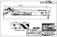
The precast concrete base is 30 feet long and weights approximately 6 tons.<br />
There are lifting points strategically placed (see drawing SS 349) to allow the<br />
base to be balanced while lifting. The recommended method for off loading the<br />
base is by forklift (forks must be able to spread to minimal 5’ and handle<br />
minimal 24” wide base). This allows the installer to use one optimal piece of<br />
equipment to handle both the modules and the base. However, the base can be<br />
easily off loaded using any crane or piece of equipment capable of lifting such a<br />
load. If using something other than a forklift be certain to use a sling apparatus<br />
in the lifting points. Using a chain is not recommended because of chips and<br />
damages to the base. The ADIEM 350 base is made of durable concrete and<br />
can be stored in any safe location covered or uncovered.<br />
Handling the ADIEM 350 Hardware Crate Package<br />
The hardware typically will be packaged inside an open crate or strapped to a<br />
pallet. This package can be unloaded with the same equipment used to lift the<br />
base or module pallets.<br />
For Technical Assistance/Customer Service Call<br />
1-800-772-7976<br />
4
Checking the Shipment<br />
Upon receipt of the shipment verify that all the parts listed on the bill of lading<br />
match what is on the truck. Using a pen physically check each part off the list,<br />
If any shortage or discrepancy exists clearly note it on the bill of lading. If you<br />
have a question about any part description call <strong>Trinity</strong> customer service.<br />
INSTALLATION<br />
Establishing Correct Anchorage<br />
The ADIEM 350 can be installed on three different surfaces: asphaltic concrete,<br />
Portland cement concrete, base and/or compacted soil. NOTE: The ADIEM<br />
350 cannot be installed on loose soil surfaces. The anchor hardware is<br />
different for each surface. Once you have established the installation surface<br />
be certain the hardware set matches what is needed (see anchor pin layout on<br />
page 5).<br />
The standard ADIEM 350 hardware package is designed for protecting Jersey<br />
barrier (24” barrier base width/ level plane for the bottom of the ADIEM base<br />
and barrier). There are an infinite variety of bracket attachments differing from<br />
the standard. If you are attaching to something other than the standard Jersey<br />
Barrier, special attachment brackets will need to be used. Verify that the<br />
attachment brackets match what is needed (see ADIEM 350 Placement below).<br />
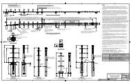
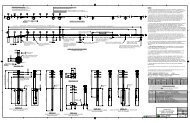
ADIEM 350 Base Placement<br />
Find drawing SS 350 in the appendix. This drawing is meant to be used in<br />
conjunction with the project drawings. Note the four typical conditions that exist<br />
for ADIEM 350 installations. It is recommended that the installer establish<br />
exact placement prior to beginning the equipment set up to place the ADIEM<br />
350 base. This will limit traffic exposure as well as costly equipment rentals.<br />
The ADIEM 350 must be placed in such a manner to prevent any potential<br />
reverse angle “snagging” or exposure to the hazard being protected. The<br />
ADIEM 350 should be offset so that the unit clearly has a smooth transition on<br />
the traffic side, while not allowing exposure on the reverse angle. Warning:<br />
incorrect placement could result in the system being improperly<br />
positioned, hindering proper performance under the guidelines of NCHRP<br />
350. Contact a <strong>Trinity</strong> technical representative if clarification is needed.<br />
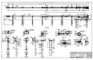
Once proper placement of the ADIEM 350 is established it is time to note the<br />
correct layout of the anchor pins and attachment hardware. Once again it is<br />
recommended that the installer establish proper layout prior to beginning the<br />
equipment set up to place the ADIEM 350 base. Regardless of which installing<br />
surface is being used ADIEM 350 anchor pins are always installed with the<br />
shortest pins going to the nose (front of the unit), and increasing in length<br />
toward the back (barrier end) of the base. This is referenced on drawing SS<br />
349 located in the appendix. See Table A on page 5 to establish correct anchor<br />
pin placement. It is helpful to have drawing SS 349 to reference when reviewing<br />
this chart.<br />
For Technical Assistance/Customer Service Call<br />
1-800-772-7976<br />
5
After establishing the correct anchor pin layout check to be sure that all anchor<br />
pin hardware and attachment bracket hardware is readily accessible. After<br />
establishing a safe workzone it is time to move the precast concrete base into<br />
the anchoring position. Refer to page three “Handling the precast concrete<br />
base” for questions about off loading. Referencing the project drawings along<br />
with drawings SS 349 and SS 350 properly align the ADIEM 350 base. The<br />
base should be firmly placed against the surface being protected with no gap<br />
allowed. Do not Remove the ADIEM 350 base handling equipment, the<br />
base may have to be moved during the anchor installation. Continue on to the<br />
anchor pin installation section.<br />
Anchor Pin <strong>Installation</strong><br />
After it is established that the unit is in position and properly aligned, anchor<br />
rods can be placed at the appropriate holes per table A above. If the<br />
installation surface is compacted soil/base or asphaltic concrete there is the<br />
possibility that the pins can be driven without drilling the surface. If that is the<br />
case then check to be sure the bracket hardware is going to line up correctly as<br />
the unit is placed. A good method to use is positioning the brackets in the<br />
bracket offset points and making sure the bracket fits flush with both the<br />
precast concrete base and the surface being protected. Adjust the base as<br />
needed to allow the attachment bracket to fit correctly. If the surface will allow<br />
the anchor pins to be driven (such as soft asphalt or base/compacted soil) then<br />
begin driving the pins using the heavy sledge hammer. Be sure the pins are<br />
driven full length.<br />
For Technical Assistance/Customer Service Call<br />
1-800-772-7976<br />
6
INSTALLATION<br />
If the installation surface is Portland cement concrete then mark (using spray<br />
paint or chalk) the pattern where the anchor holes are located. Remove the<br />
concrete base and using the 1 3/8” rock bit drill the anchor holes. Move the<br />
precast concrete base back into place, be sure the brackets are still correct,<br />
and then drive the anchor pins full length.<br />
Bracket <strong>Installation</strong><br />
Be sure to read the mixing instructions provide with the epoxy chemical grout<br />
system and comply with the manufacturer’s warnings and recommendations.<br />
When attaching the ADIEM 350 bracket it is helpful to realize that the front half<br />
of the bracket (the part that will attach to the precast concrete base) will always<br />
be the same regardless of the site conditions. That portion of the bracket is<br />
constructed of 3” x 5” angle and is easily identified by the two 1 3/8” holes<br />
matching the precast base pattern (reference SS 349). Find the two brackets<br />
necessary to attach the base to the barrier (or whatever is being protected).<br />
Place the brackets on each side of the base and attach to the base using the<br />
two 1 1/8” x 25” Hex Bolts (part #5052G) an the 1 1/8” wrench and ratchet<br />
set. The part of the bracket that attaches to the barrier has four holes for<br />
anchoring, pick any three holes to be used. An extra anchor hole is available in<br />
case reinforcing steel is encountered while drilling. Using the 1 1/4” rock bit drill<br />
the three anchor holes, mix and inject the epoxy system, insert the 7/8” x 6” all<br />
thread rod (part #4616G), then allow appropriate time for the system to harden.<br />
Once the epoxy system has hardened use the 7/8” washer (part #3725G) and<br />
7/8” hex nut (part #3735G) to secure the bracket to the barrier (or whatever is<br />
being protected). No special torque tooling is required, simply adjust to a<br />
“snug” fit using the 1 1/8” wrench and ratchet set.<br />
ADIEM 350 Module Placement<br />
Refer back to section one on page three “Handling the ADIEM 350 module<br />
packages.” Be sure there are no questions about this section. After the<br />
module pallet has been off loaded remove the protective cardboard covering,<br />
and any plastic wrapping. The modules are stacked with the “feet” (S3 x 5.7#<br />
beams) of the module facing out. The “feet” are cast in hard concrete and will<br />
remain rigid at all times in order to secure the module to the track in the precast<br />
base. When lifting ADIEM modules use back bracing and correct lifting<br />
techniques to prevent injury. The modules weigh approximately 175# each<br />
and should not be handled by one individual at a time. Using the motor oil<br />
or grease lubricant that track so that friction is at a minimum when sliding<br />
modules up the track. It might be necessary to lift up on the module to relieve<br />
any tackiness between modules.<br />
For Technical Assistance/Customer Service Call<br />
1-800-772-7976<br />
7
Do this by taking the palm of the hand and grasping each module “foot” and<br />
lifting the module. Most installers prefer to manually lift the modules; however, if<br />
that is not feasible a strap, or hoist can be used to lift the module by the “feet”<br />
only. The module should be lifted using two men positioned on each side of the<br />
module. Lift the module and gently place it (feet down- just like it will be installed<br />
on the track) on the mechanic’s “creeper” or other rolling device. Both men<br />
should stay on each side of the module for balance- the module will be top<br />
heavy so it must be held tightly. Discard the thin foam sheet that separates each<br />
module. Roll the module to the front of the precast concrete base. Another<br />
option is to disregard the rolling concept and just carry the module to the base<br />
(using sage lifting technique). Note how the l-beam “feet” will fit inside the<br />
rollformed track of the base. Lift the module and slide the module up the track<br />
until both feet are in the track. All the modules are identical with no front or back,<br />
so no particular sequence is necessary. The same two men should position<br />
themselves on each side of the base. Take the 2” module strap and position it<br />
toward the bottom two inches of the module, running the ends out toward the two<br />
previously positioned men. Note that the bottom 2-3” portion of the module<br />
is made of hard concrete- any pressure should be directed at that layer.<br />
Pull the module up the track until it becomes awkward, then push up the track<br />
applying pressure only to the bottom 2-3” portion of the module. The module<br />
should fit flush at the back of the base. Another option is to disregard the strap<br />
and push (bottom 2” layer only) the module up the track from the beginning<br />
(using safe technique). Repeat this process with all ten modules. Be sure that<br />
the modules fit tight against each other. After the modules are all installed use<br />
the brush and the ADIEM coat to completely recoat all modules. The coat should<br />
be brushed or applied heavily to any areas where the coating was “bruised” or<br />
damaged during the installation process. Any spot where it appears the coating<br />
might be penetrated should be heavily coated.<br />
Delineation<br />
Reference drawings 5904B and 5914B in the appendix. Note that drawing<br />
5904B is for roadside left and right delineation needs (with two required), while<br />
drawing 5914B is for a “gore” application with both left and right delineation.<br />
Using the caulking gun apply “liquid nails” adhesive, and install the delineator per<br />
the instructions on the appropriate drawing. The ADIEM 350 is ready for<br />
operation. As with all safety products proper maintenance is critical to future<br />
success. Please read through the maintenance section and distribute to the<br />
appropriate maintaining agency.<br />
For Technical Assistance/Customer Service Call<br />
1-800-772-7976<br />
8
MAINTENANCE<br />
Proper maintenance is critical to long term success with any roadside safety<br />
product. It is difficult to establish rigid guidelines for how often maintenance is<br />
required with so many variables involved. Each specifying agency should<br />
carefully consider all variables to establish how often maintenance is required.<br />
However, when considering varying conditions it is recommended that the<br />
ADIEM 350 have a complete inspection at least on an annual basis and a<br />
Visual inspection at least once every three months.<br />
Visual Inspection<br />
The purpose of the visual inspection is to establish the general conditions of the<br />
unit. This inspection can be done during a slow drive-by in a vehicle, or during a<br />
brief field visit. Of course, always consider the safety of other traveling<br />
motorists while viewing the unit. If a brief field visit is chosen appropriate traffic<br />
control should be established to guarantee the safety of the inspectors. The<br />
date of the inspection should be noted and records of condition field. During<br />
the visual inspection the following questions should be addressed:<br />
1. Does the unit appear to have been hit recently<br />
If the unit has been hit detailed repairs need to be made immediately. Follow<br />
the post impact instructions located on page ten.<br />
2. Is any vandalism apparent that might prevent proper performance<br />
Look for any debris (lumber, tires, etc…) that might have been thrown against<br />
the unit which might alter proper performance. The ADIEM 350 should be<br />
clear of all debris while operational. Look for any damage to the modules such<br />
as knife cuts or other intentional damage. If the module appears to have been<br />
vandalized in any way a complete inspection is needed. Look at the<br />
attachment brackets- are all the nuts still attached to the bracket attachments<br />
If not a complete inspection is needed. Look at the delineator- is it still<br />
attached securely to the first module If not, a complete inspection is needed.<br />
3. Does the coating appear to be secure to the module<br />
Look for any spots where the coating appears to be peeling or cracking. If the<br />
bond on the coating is visually breaking in any way a complete inspection is<br />
needed. The surface of the modules should be uniform in texture, if the<br />
surface appears to be distorted in any way from the original condition, a<br />
complete inspection is needed.<br />
For Technical Assistance/Customer Service Call<br />
1-800-772-7976<br />
9
MAINTENANCE<br />
Complete Inspection<br />
The purpose of the complete inspection is to establish the specific condition of<br />
the unit. This inspection should be done out of a vehicle. The required tools will<br />
be the same as those used when installing the ADIEM 350. Once again<br />
appropriate traffic control should be established to guarantee the safety of the<br />
inspectors. The date of the inspection should be noted and records of condition<br />
filed. During the complete inspection the following steps should be followed:<br />
1. Examine the unit for possible impact damage. If the unit has been hit repairs<br />
need to be made immediately. Follow the post impact instructions located on<br />
page ten.<br />
2. Verify that the ADIEM 350 base is aligned as was originally intended. If<br />
adjustments need to be made refer back to the base placement instructions in<br />
the installation section. If the base appears to have any chips or cracks repair<br />
per the base repair instructions located in the appendix.<br />
3. Check all of the nuts at the attachment brackets. If any nuts are missing new<br />
ones should be ordered. Make sure all the nuts are tight.<br />
4. Check that all of the anchor pins are still driven full length. If any have shifted<br />
use the heavy sledge hammer to drive flush.<br />
5. Check the condition of the ADIEM 350 modules. It is recommended that the<br />
modules be recoated with ADIEM coat annually regardless of condition. This<br />
will help to extend the life of the modules. ADIEM coat should be applied in<br />
dry conditions and allowed to dry for 24 hours (see ADIEM coat application<br />
instructions in the appendix). If the coating appears to be losing the bond<br />
with the module, but the surface of the module is consistent and in good<br />
condition, then remove any loose materials, clean with a moist sponge, and<br />
recoat the entire module per ADIEM coat instructions in the appendix. If the<br />
coating appears to be losing the bond with the module, and the module<br />
surface appears to have inconsistencies, repair per the module repair<br />
procedures located in the appendix. If the reinforcing cage on the module is<br />
visual the module needs to be replaced immediately.<br />
6. Check that the delineator is secure and in place on the front of the first<br />
module. Repair or replace as necessary following the delineator section<br />
under installation.<br />
For Technical Assistance/Customer Service Call<br />
1-800-772-7976<br />
10
POST- IMPACT INSTRUCTIONS<br />
The goal of the post-impact instructions is to quickly repair the ADIEM 350 and<br />
restore it to operational status. The severity of each hit can vary from slightly<br />
damaging one module to complete destruction of the unit. The required tools will<br />
be the same as those used when installing the ADIEM 350. Once again<br />
appropriate traffic control should be established to guarantee the safety of the<br />
repair crew. The date of the repair should be noted and records of the accident<br />
filled. Immediately after a hit the following steps should be followed:<br />
1. Be sure the impacting vehicle has been safely removed from the scene. It<br />
might be necessary to use the bolt cutters to cut the module reinforcing cage<br />
away from the vehicle. Use the shop broom to sweep up any debris<br />
surrounding the unit. Examine the unit for overall impact damage. The chief<br />
indicator to damage severity will be the amount of modules destroyed. Any<br />
modules with exposed reinforcing cage should be marked (using the spray<br />
paint or chalk) for complete replacement. Run the 2” module strap behind<br />
damaged modules and begin sliding the damaged modules down the track. If<br />
the hit was at very low speed or while breaking there may only be damage to<br />
the first few modules. In that case the use of the rope might be unnecessary<br />
since those modules are already at the end of the track and more easily<br />
removed. It is recommended that an extra set of modules be used to rotate<br />
so that any needed module repairs can be done out on the field. When<br />
evaluating module damage note that if the coating appears to be losing the<br />
bond with the module, but the surface of the module is consistent and in good<br />
condition, then remove any loose materials, clean with a moist sponge, and<br />
recoat the entire module per ADIEM coat instructions in the appendix. If the<br />
coating appears to be losing the bond with the module, and the module<br />
surface appears to have inconsistencies, repair per the module repair<br />
procedures located in the appendix.<br />
2. Verify that the ADIEM 350 base is aligned as was originally intended. If<br />
adjustments need to be made refer back to the base placement instructions in<br />
the installation section. If the base appears to have any chips or cracks repair<br />
per the base repair instructions located in the appendix.<br />
3. Evaluate the condition of the attachment brackets, replace the brackets if they<br />
have been bent or damaged during impact. Check all of the nuts at the<br />
attachment brackets. If any nuts are missing new ones should be ordered.<br />
Make sure all the nuts are tight.<br />
4. Check that all of the anchor pins are still driven full length. If any have shifted<br />
use the heavy sledge hammer to drive flush.<br />
5. Check that the delineator is secure and in place on the front of the first<br />
module. Repair or replace as necessary following the delineation section<br />
under installation. Be sure the unit is clear of tools and debris.<br />
For Technical Assistance/Customer Service Call<br />
1-800-772-7976<br />
11
For Technical Assistance/Customer Service Call<br />
1-800-772-7976<br />
12
2525 Stemmons Freeway<br />
Dallas, Texas 75207<br />
888-323-6374 (USA only)<br />
214-589-8140 (Outside USA)<br />
www.energyabsorption.com<br />
www.highwayguardrail.com