SRT-27 Post - Trinity Highway Products, LLC
SRT-27 Post - Trinity Highway Products, LLC
SRT-27 Post - Trinity Highway Products, LLC

Create successful ePaper yourself
Turn your PDF publications into a flip-book with our unique Google optimized e-Paper software.
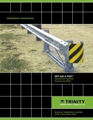
<strong>SRT</strong>-350 ® <strong>27</strong><br />
<strong>SRT</strong>-350 ® 31<br />
Guardrail End Treatment<br />
Assembly Manual<br />
Part No. 620294B Revised March 2010<br />
ENERGY ABSORPTION SYSTEMS
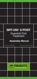
<strong>SRT</strong> -<strong>27</strong> AND <strong>SRT</strong> -31<br />
Guardrail End Treatment<br />
Instructional Manual<br />
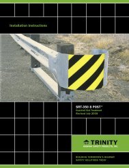
IMPORTANT: These instructions are to be used only in<br />
conjunction with the installation of the <strong>SRT</strong> -<strong>27</strong> and <strong>SRT</strong> -31<br />
systems. These instructions are for standard installations<br />
specified by the state/specifying agency. In the event the<br />
specified system installation requires or involves special<br />
circumstances, contact the appropriate state/specifying<br />
agency before proceeding. <strong>Trinity</strong> <strong>Highway</strong> <strong>Products</strong>, <strong>LLC</strong>.<br />
representative is available for consultation if required.<br />
This Manual should be available to the installation/<br />
maintenance/repair workers at all times. For additional copies,<br />
contact <strong>Trinity</strong> <strong>Highway</strong> <strong>Products</strong>, <strong>LLC</strong>. at 800-5<strong>27</strong>-6050.<br />
All information, illustrations, and specifications in this Manual are based<br />
on the latest <strong>SRT</strong> -<strong>27</strong> and <strong>SRT</strong> -31 systems information available at the<br />
time of printing. We reserve the right to make changes at any time.<br />
www.highwayguardrail.com 1 Revised: August 24, 2009
CUSTOMER SERVICE CONTACTS<br />
<strong>Trinity</strong> <strong>Highway</strong> <strong>Products</strong>, <strong>LLC</strong>. is committed to the highest level of<br />
customer service. Feedback regarding the <strong>SRT</strong> -<strong>27</strong> and <strong>SRT</strong> -31<br />
systems, their installation procedures, supporting documentation, and<br />
performance is always welcome. Our goal is to enhance highway safety<br />
through innovation. Additional information for materials and product<br />
specifications can be obtained by calling the telephone numbers or writing<br />
to the email address below:<br />
TRINITY HIGHWAY PRODUCTS:<br />
Telephone:<br />
800-644-7976 (U.S. Calls)<br />
E-mail:<br />
+1-214-589-8140 (International)<br />
productinfo@trin.net<br />
REGIONAL TELEPHONE CONTACTS:<br />
Dallas, Texas 800-5<strong>27</strong>-6050<br />
Centerville, Utah 800-772-7976<br />
Elizabethtown, Kentucky 800-282-7668<br />
Girard, Ohio 800-321-<strong>27</strong>55<br />
Orangeburg, South 800-835-9307<br />
Carolina<br />
International +1-214-589-8140<br />
SUGGESTED SAFETY RULES FOR INSTALLATION –<br />
MAINTENANCE - REPAIR<br />
* IMPORTANT SAFETY INSTRUCTIONS *<br />
Always keep this Manual in a location where it is easily accessed by<br />
persons who install, maintain, or repair the <strong>SRT</strong> -<strong>27</strong> and <strong>SRT</strong> -31<br />
systems.<br />
SAFETY SYMBOLS<br />
Below are the safety symbols that may appear on the <strong>SRT</strong> -<strong>27</strong> and<br />
<strong>SRT</strong> -31 systems or in the documentation. Read the entire Manual for<br />
suggested safety, assembly, installation, maintenance, repair, and service<br />
information.<br />
SYMBOL<br />
MEANING<br />
SAFETY ALERT SYMBOL<br />
Indicates Danger, Warning, or Caution. Failure to<br />
read and follow the Danger, Warning, and Safety or<br />
Caution indicators could result in serious injury or<br />
death to the workers and/or bystanders.<br />
WARNING – READ MANUAL<br />
Read the Manual(s) and follow all warnings and<br />
safety instructions. Failure to follow this warning<br />
could result in serious injury or death to the workers<br />
and/or bystanders.<br />
www.highwayguardrail.com 2 Revised: August 24, 2009
WARNINGS AND CAUTIONS<br />
Read all warnings, cautions, and instructions, before installing/<br />
maintaining/repairing the <strong>SRT</strong> -<strong>27</strong> and <strong>SRT</strong> -31 systems.<br />
IMPORTANT: READ SAFETY INSTRUCTIONS<br />
THOROUGHLY AND FOLLOW THE SAFE<br />
OPERATION PRACTICES WHILE INSTALLING THE<br />
<strong>SRT</strong> -<strong>27</strong> and <strong>SRT</strong> -31 SYSTEMS. Failure to follow<br />
this warning could result in serious injury or death to<br />
the workers and/or bystanders.<br />
WARNING: Read the instructions carefully. Be familiar with the<br />
complete instructions for the <strong>SRT</strong> -<strong>27</strong> and <strong>SRT</strong> -31 system<br />
before installing or repairing the <strong>SRT</strong> -<strong>27</strong> and <strong>SRT</strong> -31<br />
systems. Failure to follow this warning could result in serious<br />
injury or death in the event of a collision.<br />
WARNING: Ensure that the necessary traffic control is setup and<br />
any debris that has encroached onto the traveled way or shoulder<br />
has been removed before beginning installation or repairs. Failure<br />
to follow this warning could result in serious injury or death in the<br />
event of a collision.<br />
WARNING: Be sure adequate time is available for complete<br />
installation, before beginning the installation process. Failure to<br />
follow this warning could result in serious injury or death in the<br />
event of a collision.<br />
WARNING: Do NOT perform installation, maintenance, or repair of<br />
the <strong>SRT</strong> -<strong>27</strong> and <strong>SRT</strong> -31 systems when tired, ill, or under the<br />
influence of alcohol, drugs, or medication. Failure to follow this<br />
warning could result in serious injury or death in the event of a<br />
collision.<br />
WARNING: Do not install, maintain, or repair the <strong>SRT</strong> -<strong>27</strong> and<br />
<strong>SRT</strong> -31 systems, until you have read this Manual thoroughly.<br />
Please call <strong>Trinity</strong> <strong>Highway</strong> <strong>Products</strong> at 800-644-7976, if you do<br />
not understand the installation instructions. Failure to follow this<br />
warning could result in serious injury or death in the event of a<br />
collision.<br />
WARNING: Use only <strong>Trinity</strong> <strong>Highway</strong> <strong>Products</strong>’ parts on the<br />
<strong>SRT</strong> -<strong>27</strong> and <strong>SRT</strong> -31 systems for installation, maintenance, or<br />
repair. The installation or co-mingling of unauthorized parts is<br />
strictly prohibited. Failure to follow this warning could result in<br />
serious injury or death in the event of a vehicle impact with a<br />
system that has not been accepted by the Federal <strong>Highway</strong><br />
Administration (“FHWA”). The <strong>SRT</strong> -<strong>27</strong> and <strong>SRT</strong> -31 systems<br />
and its component parts have been accepted for state use by<br />
FHWA. However, a co-mingled system has not been accepted.<br />
WARNING: Do NOT modify the <strong>SRT</strong> -<strong>27</strong> and <strong>SRT</strong> -31<br />
systems in any way. Failure to follow this warning could result in<br />
serious injury or death in the event of a collision.<br />
WARNING: Do NOT perform installation, maintenance, or repair, if<br />
the <strong>SRT</strong> -<strong>27</strong> and <strong>SRT</strong> -31 system site, shoulder, or traveled<br />
area is covered or encroached by road debris. Failure to follow<br />
this warning could result in serious injury or death in the event of a<br />
collision.<br />
WARNING: Safety measures, incorporating traffic control devices,<br />
must be used to protect all personnel while at the installation,<br />
maintenance, or repair site. Failure to follow this warning could<br />
result in serious injury or death to the workers and/or bystanders.<br />
<strong>Trinity</strong> <strong>Highway</strong> <strong>Products</strong> offers an economical and effective truck<br />
mounted attenuator, the MPS-350, for the protection of workers in<br />
work zones. For more information on the MPS-350, call 800-644-<br />
7976 or visit the <strong>Trinity</strong> <strong>Highway</strong> <strong>Products</strong> website at<br />
www.highwayguardrail.com.<br />
WARNING: Ensure that the entire work zone site is visible at all<br />
times for safety. Failure to follow this warning could result in<br />
serious injury or death to the workers and/or bystanders.<br />
www.highwayguardrail.com 3 Revised: August 24, 2009
WARNING: Use caution when working near public roads. Be<br />
mindful of vehicles in motion nearby. Failure to follow this warning<br />
could result in serious injury or death to the workers and/or<br />
bystanders.<br />
WARNING: Ensure that all Guardrail products and delineation<br />
used meet all federal, state/specifying agency, and local<br />
specifications. Failure to follow this warning could result in serious<br />
injury or death in the event of a collision.<br />
WARNING: Ensure that your installation, repair, and maintenance<br />
meet all appropriate Manual on Uniform Traffic Control Devices<br />
(“MUTCD”) and local standards. Failure to follow this warning<br />
could result in serious injury or death in the event of a collision.<br />
WARNING: Ensure that the guardrail you install is terminated, as<br />
dictated by the state/specifying agency, pursuant to FHWA<br />
acceptance. Failure to follow this warning could result in serious<br />
injury or death in the event of a collision.<br />
WARNING: Ensure that there is proper site grading for tube and<br />
post placement, as dictated by the state/specifying agency,<br />
pursuant to FHWA acceptance. Failure to follow this warning<br />
could result in serious injury or death in the event of a collision.<br />
WARNING: Ensure that the proper Leaveout (specified area of<br />
open space in the pavement) around the posts is reserved and<br />
filled with state/specifying agency approved backfill material that<br />
will not prevent movement, for any posts installed in rigid<br />
pavement such as any thickness of concrete or asphalt more than<br />
2 inches in thickness. Failure to follow this warning could result in<br />
serious injury or death in the event of a collision.<br />
WARNING: Ensure that all of the <strong>SRT</strong> -<strong>27</strong> and <strong>SRT</strong> -31<br />
system Warnings, Cautions, and Important statements within the<br />
<strong>SRT</strong> -<strong>27</strong> and <strong>SRT</strong> -31 systems Manual are completely<br />
followed. Failure to follow this warning could result in serious<br />
injury or death in the event of a collision.<br />
WARNING: Always use safety precautions when performing<br />
installation, maintenance, repair, mixing chemicals, and/or moving<br />
heavy equipment. Wear steel toe shoes, gloves, safety goggles,<br />
and back protection. Failure to follow this warning could result in<br />
serious injury or death to the workers and/or bystanders<br />
WARNING: Ensure all wood blocks or composite blocks are<br />
routered. Failure to follow this warning could result in serious injury<br />
or death in the event of a collision.<br />
CAUTION: Ensure before installing, maintaining, or repairing the<br />
<strong>SRT</strong> -<strong>27</strong> and <strong>SRT</strong> -31 systems that no parts are frayed,<br />
damaged, or broken. Failure to follow this warning could result in<br />
serious injury to the workers and/or bystanders.<br />
www.highwayguardrail.com 4 Revised: August 24, 2009
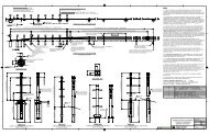
KNOW YOUR <strong>SRT</strong> -<strong>27</strong> SYSTEM<br />
<strong>SRT</strong> -<strong>27</strong> SYSTEM<br />
FOR SPECIFIC INSTALLATION, MAINTENANCE, OR REPAIR DETAILS,<br />
REFER TO<br />
THE STATE/SPECIFYING AGENCY’S STANDARD DRAWING(S) AND/OR<br />
TRINITY STANDARD LAYOUT DRAWINGS<br />
www.highwayguardrail.com 5 Revised: August 24, 2009
KNOW YOUR <strong>SRT</strong> -31 SYSTEM<br />
<strong>SRT</strong> -31 SYSTEM<br />
FOR SPECIFIC INSTALLATION, MAINTENANCE, OR REPAIR DETAILS,<br />
REFER TO<br />
THE STATE/SPECIFYING AGENCY’S STANDARD DRAWING(S) AND/OR<br />
TRINITY STANDARD LAYOUT DRAWINGS<br />
www.highwayguardrail.com 6 Revised: August 24, 2009
BILL OF MATERIAL ENGLISH (METRIC) <strong>SRT</strong>-<strong>27</strong><br />
WARNING: Use only <strong>Trinity</strong> <strong>Highway</strong> <strong>Products</strong>’ parts on the<br />
<strong>SRT</strong> -<strong>27</strong> and <strong>SRT</strong> -31 systems for installation,<br />
maintenance, or repair. The installation or co-mingling of<br />
unauthorized parts is strictly prohibited. Failure to follow this<br />
warning could result in serious injury or death in the event of<br />
a vehicle impact with a system that has not been accepted by<br />
the Federal <strong>Highway</strong> Administration (“FHWA”). <strong>SRT</strong> -<strong>27</strong> and<br />
<strong>SRT</strong> -31 POST systems and its component parts have been<br />
accepted for state use by FHWA. However, a co-mingled<br />
system has not been accepted.<br />
<strong>SRT</strong> -<strong>27</strong> SYSTEM<br />
(FOR SPECIFIC MATERIALS AND QUANTITIES, SEE STATE/SPECIFYING<br />
AGENCY OPTION(S))<br />
PN Quantity Description<br />
7G 1 12/6”/ (2.67/0.15) FLG PROTECTOR AT POST 2<br />
9G 1 12/12.5'/6' 3"/S (2.67/3.81/1.905/S) GUARDRAIL<br />
30G 1 12/12.5'/6' 3"/S (2.67/3.81/1.905/S) <strong>SRT</strong>-1 ANC<br />
(GUARDRAIL)<br />
39G 1 12/12.5'/6' 3"/S (2.67/3.81/1.905/S)<strong>SRT</strong>-2<br />
(GUARDRAIL)<br />
700A 1 CABLE ANCHOR BRACKET<br />
907G 1 12 (2.67)/BUFFER/ROLLED (TERMINAL)<br />
3000G 1 CABLE ASSEMBLY ” x 6' 6" (19 x 1981)<br />
3300G 10 5/8" (16) WASHER<br />
3340G 68 5/8" HEX HGR NUT<br />
3360G 52 5/8" DIA. x 1 ” (16 DIA. x 35) HGR SPLICE BOLT<br />
3380G 8 5/8" DIA. x 1 ” (16 DIA. x 40) HEX HEAD BOLT<br />
3400G 3 5/8" DIA x 2" (16 DIA. x 50) HGR POST BOLT (AT<br />
POST 2)<br />
3500G 4 5/8" DIA. x 10" (16 DIA. x 255) HGR POST BOLT<br />
3240G 2 5/16” (8) WASHER (AT POST 1)<br />
3245G 2 5/16” (8) HEX NUT (AT POST 1)<br />
3391G 1 5/8" DIA x 1 ” (19 DIA. x 75) HEX BOLT (A325) (AT<br />
STRUT)<br />
3900G 2 1" (25) WASHER (AT CABLE)<br />
3910G 2 1" (25) HEX NUT (AT CABLE)<br />
14578G 5 6’0” (1830) SYT POST, W6 X 8.5 (W150 x 13)<br />
4076B 4 ROUTED WOOD BLOCK 6" x 8" x 14" (150 x 200 x<br />
360) DR<br />
4211G 2 5/16” DIA X 1 ” (8 X 44) HEX BOLT (AT POST 1)<br />
9960G 4 SLOT GUARD BRACKET<br />
34052A 1 CR POST 1 BOT W6X15 (W150 x 22.5)<br />
34056A 1 CR POST 1 TOP W6 x 8.5<br />
34050G 1 ANGLE STRUT 3” X 3” X 1/4” (75 x 75 x 6)<br />
33909G 1 CABLE ANCHOR BRACKET (AT POST 1)<br />
4389G 2 7/16” FLAT WASHER<br />
4390G 2 5/8" DIA x 1 “ HEX HD BOLT<br />
4393G 2 7/16” LOCK WASHER<br />
4396G 2 7/16” HEX NUT<br />
34054G 1 POST SHELF ANGLE (AT POST 2)<br />
Delineation Options<br />
PN Quantity Description<br />
6665B 1 16" x 16" (400 x 400) Striped (Yellow/Black)<br />
Reflective Sheeting<br />
Note: See state/specifying agency’s MUTCD for<br />
options or proper delineation.<br />
www.highwayguardrail.com 7 Revised: August 24, 2009
BILL OF MATERIAL ENGLISH (METRIC) <strong>SRT</strong>-31<br />
WARNING: Use only <strong>Trinity</strong> <strong>Highway</strong> <strong>Products</strong>’ parts on the <strong>SRT</strong> -<strong>27</strong><br />
and <strong>SRT</strong> -31 systems for installation, maintenance, or repair. The<br />
installation or co-mingling of unauthorized parts is strictly prohibited.<br />
Failure to follow this warning could result in serious injury or death in<br />
the event of a vehicle impact with a system that has not been accepted<br />
by the Federal <strong>Highway</strong> Administration (“FHWA”). <strong>SRT</strong> -<strong>27</strong> and<br />
<strong>SRT</strong> -31 POST systems and its component parts have been accepted<br />
for state use by FHWA. However, a co-mingled system has not been<br />
accepted.<br />
<strong>SRT</strong> -31 SYSTEM<br />
(FOR SPECIFIC MATERIALS AND QUANTITIES, SEE STATE/SPECIFYING<br />
AGENCY OPTION(S))<br />
PN Quantity Description<br />
7G 3 12/6”/ (2.67/0.15) FLG PROTECTOR AT POST 2, 4,<br />
& 6<br />
30G 1 12/12.5'/6' 3"/S (2.67/3.81/1.905/S) <strong>SRT</strong>-1 ANC<br />
(GUARDRAIL)<br />
39G 1 12/12.5'/6' 3"/S (2.67/3.81/1.905/S)<strong>SRT</strong>-2<br />
(GUARDRAIL)<br />
700A 1 CABLE ANCHOR BRACKET<br />
907G 1 12 (2.67)/BUFFER/ROLLED (TERMINAL)<br />
3000G 1 CABLE ASSEMBLY ” x 6' 6" (19 x 1981)<br />
3300G 12 5/8”(16) WASHER<br />
3340G 67 5/8”(16) HEX HGR NUT<br />
3360G 52 5/8”DIA. x 1 ” (16 DIA. x 35) HGR SPLICE BOLT<br />
3380G 8 5/8”DIA. x 1 ” (16 DIA. x 40) HEX HEAD BOLT<br />
3400G 4 5/8” DIA x 2" (16 DIA. x 50) HGR POST BOLT (AT<br />
POST 2&4)<br />
3240G 2 5/16” (8) WASHER (AT POST 1)<br />
3245G 2 5/16” (8) HEX NUT (AT POST 1)<br />
3391G 2 5/8”DIA X 1 ” (19 DIA. x 75) HEX BOLT (A325) (AT<br />
STRUCT)<br />
3900G 2 1" (25) WASHER (AT CABLE)<br />
3910G 2 1" (25) HEX NUT (AT CABLE)<br />
15000G 5 6’0” (1830) SYT POST, W6 X 8.5 (W150 X 13)<br />
4211G 2 5/16”DIA X 1 ” (8 X 44) HEX BOLT (AT POST 1)<br />
4419G 1 5/8” DIA X 1 ” (16 X 44) COUNTERSUNK HD BOLT<br />
(AT POST 6)<br />
9960G 4 SLOT GUARD<br />
10967G 1 12/9’4.5/3’1.5/S <strong>SRT</strong>-3 GUARDRAIL<br />
34052A 1 CR POST 1 BOT W6X15 (W150 X 22.5)<br />
34053A 1 CR POST 1 TOP W6 x 8.5<br />
34054G 1 HBA POST 1 & 2 BOT (TS 6 x 4) POST SHELF<br />
ANGLE (AT POST 2)<br />
33875G 1 ANGLE STRUT 3” X 3” X ” (75 x 75 x 6)<br />
33909G 1 CABLE ANCHOR BRACKET (AT POST 1)<br />
Delineation Options<br />
PN Quantity Description<br />
6665B 1 16" x 16" (400 x 400) Striped (Yellow/Black) Reflective<br />
Sheeting<br />
Note: See state/specifying agency’s MUTCD for options<br />
or proper delineation.<br />
www.highwayguardrail.com 8 Revised: August 24, 2009
INSTALLING THE <strong>SRT</strong> -<strong>27</strong> & 31 SYSTEMS<br />
Use <strong>Trinity</strong> <strong>Highway</strong> <strong>Products</strong>’ drawings for the <strong>SRT</strong> -<strong>27</strong> and <strong>SRT</strong> -31<br />
Systems with these instructions. Review the state/specifying agency’s<br />
standard drawing(s) for this system. Details will be specific to the project<br />
or site locations. The <strong>SRT</strong> -<strong>27</strong> and <strong>SRT</strong> -31 Systems have a straight<br />
flare like the <strong>SRT</strong> /HBA 6 <strong>Post</strong> System. At <strong>Post</strong>s 1, a CR <strong>Post</strong> is used<br />
in place of the HBA post. The Steel Yielding Terminal <strong>Post</strong> (SYTP) are<br />
used at <strong>Post</strong> 2-6. The <strong>SRT</strong> -<strong>27</strong> system has blockouts on <strong>Post</strong>s 3 through<br />
6. The <strong>SRT</strong> -31 system has no blockouts on any of the posts. The same<br />
equipment and expertise are required for both systems.<br />
MATERIALS<br />
WARNING: Ensure that there is proper site grading for tube and<br />
post placement as dictated by the state/specifying agency,<br />
pursuant to FHWA acceptance. Failure to follow this warning<br />
could result in serious injury or death in the event of a collision.<br />
WARNING: Ensure that the proper Leaveout (specified area of<br />
open space in the pavement) around the posts is reserved and<br />
filled with state/specifying agency approved backfill material that<br />
will not prevent movement, for any posts installed in rigid<br />
pavement such as any thickness of concrete or asphalt more than<br />
2 inches in thickness. Failure to follow this warning could result in<br />
serious injury or death in the event of a collision.<br />
WARNING: Ensure that all Guardrail products and delineation<br />
used meet all federal, state/specifying agency, and local<br />
specifications. Failure to follow this warning could result in serious<br />
injury or death in the event of a collision.<br />
As packaged, the <strong>SRT</strong> -<strong>27</strong> and <strong>SRT</strong> -31 systems include all materials<br />
needed for the installation. Note that concrete footings are NOT required.<br />
TOOLS REQUIRED<br />
The following list shows recommended tools for installation of the <strong>SRT</strong> -<br />
<strong>27</strong> and <strong>SRT</strong> -31 systems:<br />
•<br />
9 / 16 ” (14 mm) Socket or Wrench<br />
•<br />
15 / 16 ” (24 mm) Socket or Wrench<br />
• 1 1 / 4 ” (32 mm) Socket or Wrench<br />
• 1 1 / 2 ” (38 mm) Socket or Wrench<br />
• Augers<br />
• <strong>Post</strong> Pounders (commonly used in driving posts)<br />
The following list shows recommended tools for the repair of the <strong>SRT</strong> -<br />
<strong>27</strong> and <strong>SRT</strong> -31 systems. However, since repair is directed by the<br />
state/specifying agency, they may have more specific guidelines.<br />
• Channel lock pliers<br />
• Sledge hammer<br />
• <strong>Post</strong> removal tool and other normal guardrail tools<br />
SITE PREPARATION<br />
Site grading is usually necessary for the proper placement of the CR<br />
posts and the Steel Yielding Terminal (SYT) posts. Use the<br />
state/specifying agency’s specifications and standard drawings for the<br />
site grading. <strong>Trinity</strong> does not direct grading. Complete this grading,<br />
before the start of the installation of the <strong>SRT</strong> -<strong>27</strong> AND <strong>SRT</strong> -31 systems.<br />
WARNING: Ensure that there is proper site grading for tube and<br />
post placement as dictated by the state/specifying agency,<br />
pursuant to FHWA acceptance. Failure to follow this warning<br />
could result in serious injury or death in the event of a collision.<br />
www.highwayguardrail.com 9 Revised: August 24, 2009
INSTALLATION<br />
The post installation of the <strong>SRT</strong> -<strong>27</strong> AND <strong>SRT</strong> -31 systems should be<br />
per the following <strong>Post</strong> Installation Sections. If there are special field<br />
conditions encountered when installing the <strong>SRT</strong> -<strong>27</strong> and <strong>SRT</strong> -31<br />
systems, contact the state/specifying agency. <strong>Trinity</strong> <strong>Highway</strong> <strong>Products</strong>,<br />
<strong>LLC</strong>. at 1-800-644-7976, is available to assist the state/specifying agency,<br />
if needed.<br />
POST INSTALLATION<br />
Complete the following instructions for the installation of the SYT posts<br />
and the CR posts. When installing posts in rigid pavement, see the <strong>Post</strong><br />
Installed in Rigid Material section, below.<br />
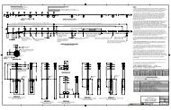
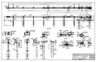
POST LAYOUT<br />
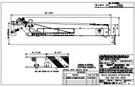
The <strong>SRT</strong> -<strong>27</strong> and <strong>SRT</strong> -31 <strong>Post</strong> System is a 37’6” (11.43m) that utilizes<br />
a straight flare. Complete the following steps to layout the posts. See<br />
Figure 1.<br />
Step<br />
Actions<br />
1 Start at line <strong>Post</strong> 9 of the guardrail run and etc.<br />
2 Extend the guardrail tangent line from <strong>Post</strong> 9 to establish Point<br />
7T. (See Figure 1)<br />
Figure 1<br />
3 Extend the guardrail tangent line from Point 7T to establish Point<br />
1T. See Figure 1.<br />
4 Measure from Point 1T an offset of 4’0” (1.21 m) perpendicular<br />
to the road to establish the back side of the guardrail for Point 1.<br />
5 Measure the offsets of <strong>Post</strong>s 8 and 7.<br />
6 Establish a straight line between Point 1 and Point 7. This line<br />
represents to back side of the guardrail for both of the systems.<br />
7 Between Points 1 and 7 on the back side of the guardrail line,<br />
establish Points 2 thorough 6 at 6’3” (1905 mm) intervals.<br />
INSTALLING THE SYT POSTS<br />
Complete the following steps to install the SYT posts:<br />
Step<br />
Actions<br />
1. Install the SYT <strong>Post</strong> PN-14578G (<strong>SRT</strong>-<strong>27</strong>) or SYT <strong>Post</strong> PN-<br />
15000G (<strong>SRT</strong> -31) at location 6 through 2, spaced at 6’3”<br />
(1905 mm). Select Option A or Option B for the post installation.<br />
Option<br />
A<br />
Option<br />
B<br />
<strong>SRT</strong> LAYOUT<br />
Drive posts into the ground.<br />
1. Drill 12” (300 mm) maximum diameter holes<br />
approximately 44" (1120 mm) deep for the <strong>SRT</strong> -<br />
<strong>27</strong> system or 40” (1020 mm) deep for the <strong>SRT</strong> -<br />
31.<br />
2. Insert the 6' 0" (1830 mm) SYT post into these<br />
holes.<br />
3. Backfill the hole with compactable materials in 6"<br />
(150 mm) lifts and compact with pneumatic<br />
equipment to optimum compaction.<br />
Note: If compactable, the material removed from<br />
the hole may be used for the backfill.<br />
www.highwayguardrail.com 10 Revised: August 24, 2009
Figure 2<br />
Note: In either option within the previous step, the center of the<br />
” (13) or 13/16” (21) yielding holes in the post is approximately<br />
at the finished grade. (See Figure 2)<br />
WARNING: Ensure that the proper Leaveout (specified<br />
area of open space in the pavement) around the posts is<br />
reserved and filled with state/specifying agency approved<br />
backfill material that will not prevent movement, for any<br />
posts installed in rigid pavement such as any thickness of<br />
concrete or asphalt more than 2 inches in thickness.<br />
Failure to follow this warning could result in serious injury<br />
INSTALLING CR BOTTOM POSTS<br />
Complete the following steps to install CR Bottom <strong>Post</strong>s at locations 1:<br />
Step<br />
Actions<br />
1. Orient the lower embedded CR <strong>Post</strong> so the ” diameter Strut<br />
attachment hole will be closer to the nose of the system.<br />
2. Select Option A or Option B for this installation.<br />
Option 1. Drive the CR Bottom <strong>Post</strong>s (PN-34052A)<br />
A<br />
approximately 71.5” (1815 mm) to the<br />
optimum height, where the strut hole is<br />
Option<br />
B<br />
approximately at finished grade.<br />
1. Drill a 12” (300 mm) pilot hole approximately<br />
72” (1830 mm) deep.<br />
2. Install the CR Bottom <strong>Post</strong> to the optimum<br />
height, where the strut hole is approximately<br />
at finished grade.<br />
3. Backfill the hole with compactable materials<br />
in 6" (150 mm) lifts and compact with<br />
pneumatic equipment to optimum<br />
compaction.<br />
Note: If compactable, the material removed from<br />
the hole may be used for the backfill.<br />
WARNING: Ensure that the proper Leaveout (specified<br />
area of open space in the pavement) around the posts is<br />
reserved and filled with state/specifying agency approved<br />
backfill material that will not prevent movement, for any<br />
posts installed in rigid pavement such as any thickness of<br />
concrete or asphalt more than 2 inches in thickness.<br />
Failure to follow this warning could result in serious injury<br />
or death in the event of a collision.<br />
www.highwayguardrail.com 11 Revised: August 24, 2009
POST INSTALLED IN RIGID MATERIAL<br />
Provide the proper Leaveout around a post when installing the post in any<br />
thickness of concrete or asphalt more than 2 inches thick. SYT posts<br />
require the leaveout shown in Figure 3.<br />
Figure 3<br />
WARNING: Ensure that the proper Leaveout (specified area of<br />
open space in the pavement) around the posts is reserved and<br />
filled with state/specifying agency approved backfill material that<br />
will not prevent movement, for any posts installed in rigid<br />
pavement such as any thickness of concrete or asphalt more than<br />
2 inches in thickness. Failure to follow this warning could result in<br />
serious injury or death in the event of a collision.<br />
INSTALLING CR & SYT POSTS WHEN<br />
ENCOUNTERING ROCK<br />
Complete the following steps to install CR and SYT posts when<br />
encountering rock:<br />
Step<br />
Actions<br />
1 Select Option A or Option B when encountering rock, unless<br />
there is a more restrictive state/specifying agency specification.<br />
Option<br />
A<br />
If rock is encountered with depth of 20" (510<br />
mm) or less is required to install a full-length CR<br />
post or SYT post.<br />
1. Drill a 12" - 16" (300 mm - 400 mm) diameter<br />
hole into the rock 2" (50 mm) deeper than<br />
the required embedment depth. See the<br />
INSTALLING THE SYT POSTS or<br />
INSTALLING CR BOTTOM POST sections<br />
for depth location.<br />
2. Place granular material or small pieces of<br />
the drilled rock in the bottom 2" (50 mm) of<br />
the hole for drainage.<br />
3. Insert the CR Bottom <strong>Post</strong> or SYT <strong>Post</strong> into<br />
the hole.<br />
Continues on next page.<br />
www.highwayguardrail.com 12 Revised: August 24, 2009
Option<br />
B<br />
4. Backfill the hole with compactable materials<br />
in 6" (150 mm) lifts and compact with<br />
pneumatic equipment to optimum<br />
compaction.<br />
5. Ensure that the finished guardrail height for<br />
the <strong>SRT</strong> -<strong>27</strong> is approximately <strong>27</strong> ” (706<br />
mm) or <strong>SRT</strong> -31 is approximately 31” (787<br />
mm) above the finished grade or as the<br />
state/specifying agency plans indicate.<br />
6. Ensure that the CR <strong>Post</strong> does not project<br />
more than 4” (100 mm) above the finished<br />
grade.<br />
Note: If compactable, the material removed from the<br />
hole may be used for the backfill.<br />
If rock is encountered where a depth of more<br />
than 20” (510 mm) is required to install a fulllength<br />
CR post or SYT post.<br />
1. Drill a 12" - 16" (300 mm - 400 mm) diameter<br />
hole 22" (560 mm) deep into the rock.<br />
2. Insert the CR <strong>Post</strong> or SYT <strong>Post</strong> into the hole<br />
and measure from the bottom of the post to<br />
the finished grade.<br />
3. Remove the post from the hole. Measure<br />
and mark from the top of the post the length<br />
to remove from the bottom.<br />
4. Cut off the measured length from the bottom<br />
of the post.<br />
5. Place granular material or small pieces of<br />
the drilled rock in the bottom 2" (50 mm) of<br />
the hole for drainage.<br />
6. Install the CR <strong>Post</strong> or SYT <strong>Post</strong> in the hole.<br />
7. Backfill the hole with compactable materials<br />
in 6" (150 mm) lifts and compact with<br />
pneumatic equipment to optimum<br />
compaction.<br />
8. Ensure that the finished guardrail height for<br />
the <strong>SRT</strong>-<strong>27</strong> is approximately <strong>27</strong> ” (706<br />
mm) or <strong>SRT</strong>-31 is approximately 31” (787<br />
mm) above the finished grade or as the<br />
state/specifying agency plans indicate.<br />
9. Ensure that the Bottom CR <strong>Post</strong> does not<br />
project more than 4” (100) above the<br />
finished grade.<br />
Note: If compactable, the material removed from<br />
the hole may be used for the backfill.<br />
WARNING: Ensure that the proper Leaveout (specified<br />
area of open space in the pavement) around the posts is<br />
reserved and filled with state/specifying agency approved<br />
backfill material that will not prevent movement, for any<br />
posts installed in rigid pavement such as any thickness of<br />
concrete or asphalt more than 2 inches in thickness.<br />
Failure to follow this warning could result in serious injury<br />
or death in the event of a collision.<br />
INSTALLING CR TOP POST<br />
Complete the following steps to install the CR Top <strong>Post</strong>s after the Bottom<br />
<strong>Post</strong>s have been installed:<br />
Step<br />
Actions<br />
1. Install the Top post (PN-34056A) for <strong>SRT</strong> -<strong>27</strong> system or (PN-<br />
34053A) for <strong>SRT</strong> -31 system at <strong>Post</strong> 1, by aligning the ears of<br />
the top and bottom posts.<br />
2. Insert a 5/16” (8 mm) diameter x 1 ” (44 mm) Hex Head Bolt<br />
(PN-4211G) in each of the 3/8” (10 mm) holes in the bottom and<br />
top post plates. For the inserted bolts, place a 5/16” (8 mm)<br />
Washer (PN-3240G) under the 5/16” (8 mm) Hex Nut (PN-<br />
3245G) Tighten the bolt. (There is no torque requirement for<br />
these bolts.)<br />
www.highwayguardrail.com 13 Revised: August 24, 2009
INSTALLING THE STRUT<br />
Complete the following steps when installing the strut:<br />
Note: Since a portion of the angle strut will be below grade, the installer<br />
must provide a shallow valley/trough for installation of the strut.<br />
Step<br />
Actions<br />
1. Place the Angle Strut (PN-34050G) <strong>SRT</strong> TM -<strong>27</strong> or (PN-33875G)<br />
<strong>SRT</strong> -31 outside the post plate (ear) of <strong>Post</strong> 1 and the backside<br />
of the SYT post at <strong>Post</strong> 2. (See Figure 4)<br />
Figure 4<br />
2. Insert a 5/8” (16 mm) diameter x 1 ” (44 mm) High Strength<br />
Hex Head Bolt (PN-3391G) through the ” (19 mm) hole in the<br />
post plate and through the slot in the strut at <strong>Post</strong> 1. (See<br />
Figure 4)<br />
3. Place a 5/8” (16 mm) Washer (PN-3300G) on the bolt. Place a<br />
5/8” (16 mm) Hex Nut (PN-3340G) on the end of the bolt. (See<br />
Figure 4)<br />
4. At <strong>Post</strong> 2 for the <strong>SRT</strong> -<strong>27</strong>, insert a 7/16” (11 mm) diameter x 1<br />
” (44 mm) high strength Hex Head Bolt ( PN-4390G) with a<br />
7/16” (11 mm) Washer (PN-4389G) on the bolt through each of<br />
the ” (13 mm) ground holes of the SYT post and through the<br />
slots of the strut. Place a 7/16” (11 mm) Lock Washer (PN-<br />
4393G) on each of the bolts. Place a 7/16” (11 mm) Hex Nut<br />
(PN-4396G) on the end of the bolts.<br />
5. At <strong>Post</strong> 2 for the <strong>SRT</strong> -31, insert a 5/8” (16 mm) diameter x 1<br />
” (44 mm) high strength Hex Head Bolt ( PN-3391G) with a<br />
5/8” (16 mm) Washer (PN-3300G) on the bolt through the 13/16”<br />
(21 mm) ground hole of the SYT post and through the slot of the<br />
strut. Place a 5/8” (16 mm) Washer (PN-3300G) on the end<br />
bolt. Place a 5/8” (16 mm) Hex Nut (PN-3340G) on the end of<br />
the bolt.<br />
6. Tighten all of the bolts. (There is no torque requirements for<br />
these bolts.)<br />
www.highwayguardrail.com 14 Revised: August 24, 2009
ARRANGING RAIL PANELS FOR <strong>SRT</strong>-<strong>27</strong> AND <strong>SRT</strong>-31<br />
Complete the following steps to arrange the rail panels for the <strong>SRT</strong> -<strong>27</strong><br />
and <strong>SRT</strong>-31 system:<br />
Step<br />
Actions<br />
1. Layout the guardrails (PN-30G, PN-39G) so the Slot Guard<br />
attachment holes are at the end of the slots AWAY from <strong>Post</strong> 1.<br />
(See Figure 5) Position the guardrails with the slots between<br />
<strong>Post</strong>s 1 and 2, <strong>Post</strong>s 2 and 3, <strong>Post</strong>s 3 and 4, and <strong>Post</strong>s 4<br />
and 5.<br />
Slot guard<br />
attachment<br />
hole<br />
Toward <strong>Post</strong> 1<br />
Figure 5<br />
INSTALLING RAIL PANELS FOR THE <strong>SRT</strong>-<strong>27</strong><br />
SYSTEM<br />
Complete the following steps to install the rail panels for the <strong>SRT</strong> -<strong>27</strong><br />
system:<br />
Step<br />
Actions<br />
1. Splice and post bolt the 12' 6" (3.81m) rail panel (PN-9G) at<br />
<strong>Post</strong> 7, to the run of guardrail. Use hardware provided by the<br />
standard guardrail supplier.<br />
Note: Lap the terminal rail in the direction of traffic, unless the<br />
state/agency's policy dictates otherwise.<br />
2. Insert a 5/8” x 10” (16 mm x 255 mm) <strong>Post</strong> Bolt (PN-3500G)<br />
through the Routered Wood (4076B) or composite blockout at<br />
<strong>Post</strong>s 5, 4, and 3. Place a 5/8” (16 mm) Hex HGR Nut on<br />
inserted bolt to secure. Tighten the bolts. (There is no torque<br />
requirement for these bolts.)<br />
3. Insert a 5/8” x 2” (16 mm x 50 mm) HGR <strong>Post</strong> Bolt (PN-3400G)<br />
through the two holes in the Flange Protector (PN-7G) and the<br />
<strong>Post</strong> Shelf Angel (PN-34054G) at <strong>Post</strong> 2. Place a 5/8” (16 mm)<br />
Hex HGR Nut on inserted bolts to secure. Tighten the bolts.<br />
(There is no torque requirement for these bolts.)<br />
4. Splice the 12' 6" (3.81 m) Rail Panel (PN-9G) to the second 12'<br />
6" (3.81 m) Rail Panel (PN-39G) , at <strong>Post</strong> 5, with eight (8) 5 / 8 " x<br />
1 1 / 4 " (16 mm x 32 mm) HGR Splice Bolts (PN-3360G). Place a<br />
5/8” (16 mm) Hex HGR Nut on inserted bolt to secure. Tighten<br />
the bolt. (There is no torque requirement for these bolts.)<br />
5. Insert a 5/8” x 10” (16 mm x 255 mm) HGR <strong>Post</strong> Bolt through<br />
the rail panel, the Routed Wood Block (4076B), or composite<br />
blockout at <strong>Post</strong> 6. Place a 5/8” (16 mm) Hex HGR Nut on<br />
inserted bolt to secure. Tighten the bolts. (There is no torque<br />
requirement for these bolts.)<br />
6. Splice the 12’6” (3.81 m) Rail Panel (PN-39G) to the first 12’6”<br />
(3.81 m) Rail Panel (PN-30G), at <strong>Post</strong> 3, with eight (8) 5/8” x 1-<br />
1/4” (16 mm x 32 mm) HGR Splice Bolts (PN-3360G). Place a<br />
5/8” (16 mm) Hex HGR Nut on inserted bolts to secure. Tighten<br />
the bolts. (There is no torque requirement for these bolts.)<br />
7. Insert a 5/8” x 2” (16 mm x 50 mm) HGR <strong>Post</strong> Bolt through the<br />
rail panel at <strong>Post</strong> 1. Place a 5/8” (16 mm) Hex HGR Nut on<br />
inserted bolt to secure. Tighten the bolts. (There is no torque<br />
requirement for these bolts.)<br />
www.highwayguardrail.com 15 Revised: August 24, 2009
INSTALLING RAIL PANELS FOR <strong>SRT</strong>-31 SYSTEM<br />
Complete the following steps to arrange the rail panels for the <strong>SRT</strong> -31<br />
system:<br />
Step<br />
Actions<br />
1. Splice the 9’4.5” (2.86 m)<br />
Rail Panel (PN-10967G) to the run of the guardrail. Use<br />
hardware provided by the standard guardrail supplier.<br />
Note: Lap the terminal rail in the direction of traffic, unless the<br />
state/agency’s policy dictates otherwise.<br />
2. Insert a 5/8” x 2” (16 mm x 50 mm) HGR <strong>Post</strong> Bolt (PN-3400G)<br />
through the Flange Protector (PN-7G) at <strong>Post</strong> 4. Place a 5/8”<br />
(16 mm) Hex HGR Nut (PN-3340G) on inserted bolt to secure.<br />
Tighten the bolt. (There is no torque requirement for this bolt)<br />
3. Insert a 5/8” x 2” (16 mm x 50 mm) HGR <strong>Post</strong> Bolt (PN-3400G)<br />
through the two holes in the Flange Protector (PN-7G) and the<br />
<strong>Post</strong> Shelf Angel (PN-34054G) at <strong>Post</strong> 2. Place a 5/8” (16 mm)<br />
Hex HGR Nut on inserted bolts to secure. Tighten the bolts.<br />
(There is no torque requirement for these bolts.)<br />
4. Insert a 5/8” x 1 ” (16 mm x 44 mm) Countersunk HD Bolt (PN-<br />
4491G) through the Rail Panel (PN-10967G) and Flange<br />
Protector at <strong>Post</strong> 6. Place a 5/8” (16 mm) Hex HGR Nut on<br />
inserted bolt to secure. Tighten the bolts. (There is no torque<br />
requirement for these bolts)<br />
5. Splice the 9’4.5” (2.86 m) Rail Panel (PN-10967G) to the second<br />
12’6” (3.81 m) Rail Panel (PN-39G), at <strong>Post</strong> 5, with eight (8) 5/8”<br />
x 1-1/4” (16 mm x 32 mm) HGR Splice Bolts (PN-3360G). Place<br />
a 5/8” (16 mm) Hex HGR Nut (PN-3340G) on inserted bolts to<br />
secure. Tighten the bolts. (There is no torque requirement for<br />
these bolts.)<br />
6. Splice the 12’6” (3.81 m) Rail Panel (PN-39G) to the first 12’6”<br />
(3.81 m) Rail Panel (PN-30G), at <strong>Post</strong> 3, with eight (8) 5/8” x 1-<br />
1/4” (16 mm x 32 mm) HGR Splice Bolts. Place a 5/8” (16 mm)<br />
Hex HGR Nut (PN-3340G) on inserted bolts to secure. Tighten<br />
the bolts. (There is no torque requirement for these bolts.)<br />
7. Insert a 5/8” x 2” (16 mm x 50 mm) HGR <strong>Post</strong> Bolt through the<br />
rail panel at <strong>Post</strong> 1. Place a 5/8” (16 mm) Hex HGR Nut on<br />
inserted bolt to secure. Tighten the bolts. (There is no torque<br />
requirement for these bolts.)<br />
INSTALLING THE SLOT GUARDS<br />
Complete the following steps to install the Slot Guards:<br />
Step<br />
Actions<br />
1. Place the Slot Guards (PN-9960G) against the backside of the<br />
guardrail panels with the deflector angle gap opening toward<br />
(closest to) the elongated slots. Align the six holes in the Slot<br />
Guard with the six holes in the guardrail panel near the<br />
elongated slots.<br />
2. Bolt each Slot Guard to the backside of the guardrail panels with<br />
six (6) 5 / 8 " x 1 1 / 4 " (16 mm x 32 mm) Splice Bolts (PN-3340G) and<br />
Hex Nuts (PN-3360G).<br />
INSTALLING THE CABLE ANCHOR ASSEMBLY<br />
Complete the following steps to install the cable anchor assembly:<br />
Step<br />
Actions<br />
1. Place a 5/8” (16 mm) Round Washer (PN-3300G) on each of<br />
the eight (8) 5/8” x 11/2” (16 mm x 38 mm) Hex Head Bolt (PN-<br />
3380G).<br />
2. Insert the bolts through the traffic side of the rail panel and the<br />
Cable Anchor Bracket (PN-700A) on the backside of the<br />
Guardrail panel. Secure the Hex Head Bolts with a Hex HGR<br />
Nut (PN-3380G) on each bolt. Tighten each bolt. (There is no<br />
www.highwayguardrail.com 16 Revised: August 24, 2009
torque requirement for these bolts.)<br />
3. Slide one end of the Cable (PN-3000G) into the Cable Anchor<br />
Bracket and the other end through the hole between the top and<br />
bottom CR posts at location 1.<br />
4. Place a 1" (25 mm) Washer (PN-3900G) and a 1” (25 mm) Hex<br />
Nut (PN-3910G) on the end of the cable that extends through<br />
the Cable Anchor Bracket.<br />
5. Place the Cable Anchor Bracket (PN-33909G) on the cable end<br />
placed between the top and bottom CR posts.<br />
6. Place a 1” (25 mm) Washer and 1” (25 mm) Hex Nut on the end<br />
of the cable. (See Figure 6)<br />
Figure 6<br />
7. Restrain the cable with vise grip pliers at the end being<br />
tightened to avoid twisting the cable.<br />
8. Tighten the Hex Nuts on the cable ends, until the cable is taut.<br />
The cable is considered taut, when it does not deflect more than<br />
1 inch when pressure is applied by hand in an up or down<br />
direction.<br />
INSTALLING THE END SECTION<br />
Complete the following steps to install the end section:<br />
Step<br />
Actions<br />
1. Connect the end section (PN-907G) to the end of the guardrail<br />
panel with four (4) 5 / 8 " x 1 1 / 4 " (16 mm x 32 mm) HGR Splice Bolts<br />
(PN-3360G). Place a 5/8” (16 mm) Hex HGR Nut (PN-3340G)<br />
on inserted bolts to secure. Tighten the bolts. (There is no<br />
torque requirement for these bolts.)<br />
2. Install high intensity Reflective Sheeting (PN-6665B) on the front<br />
face of the end section, per the state/specifying agency’s<br />
MUTCD for options or proper delineation.<br />
Note: The reflective sheeting is an option to the <strong>SRT</strong> -<strong>27</strong> and<br />
<strong>SRT</strong> -31 systems and to be ordered separate from the <strong>SRT</strong> -<strong>27</strong><br />
and <strong>SRT</strong> -31 package.<br />
WARNING: Ensure that all Guardrail products and<br />
delineation used meet all federal, state/specifying<br />
agency, and local specifications. Failure to follow this<br />
warning could result in serious injury or death in the<br />
event of a collision.<br />
www.highwayguardrail.com 17 Revised: August 24, 2009
<strong>SRT</strong> -<strong>27</strong> or <strong>SRT</strong> -31 INSTRUCTIONAL CHECKLIST<br />
STATE: _____________PROJECT: ___________________________________<br />
DATE: ______________LOCATION: __________________________________<br />
The finished guardrail height is approximately <strong>27</strong> 3 / 4 " (706 mm)<br />
above the finished grade for the <strong>SRT</strong> -<strong>27</strong> or 31” (787 mm) for the<br />
<strong>SRT</strong> -31 system, or as the state/specifying agency plans indicate.<br />
Any site grading needed was completed, before the start of the<br />
installation of the <strong>SRT</strong> -<strong>27</strong> or <strong>SRT</strong> -31 system.<br />
The ears of the bottom CR posts do not protrude more than 4”<br />
(100 mm) above the finished grade measured by the AASHTO<br />
5’0” (1.5 m) cord method. Site grading may be necessary to meet<br />
this requirement.<br />
The anchor cable is taut and correctly installed (the cable should<br />
be rechecked after installation to be sure it hasn’t relaxed). The<br />
taut cable does not deflect more than 1 inch, when pressure is<br />
applied by hand in an up or down direction.<br />
The rail panel is not attached to the post at locations 2, 3, 4, and<br />
5.<br />
No rectangular washers are used on the face of the rail.<br />
Slot Guards are in place against the backside of the guardrail<br />
panels with the deflector angle gap opening toward (closest to) the<br />
elongated slots. Slot Guards are oriented per Figure 5.<br />
Rail panels are oriented correctly and lapped in the direction of<br />
traffic unless the agency's policy dictates otherwise.<br />
If backfilled, the backfill material around the posts is properly<br />
compacted.<br />
The SYT posts (<strong>Post</strong>s 2 through 6) have four yielding holes. They<br />
are located parallel to the roadway with the center of the holes<br />
located approximately at the finished grade.<br />
The recesses are filled with state/specifying agency approved<br />
backfill material that will not prevent movement, for any posts<br />
installed in rigid pavement such as any thickness of concrete or<br />
asphalt more than 2 inches in thickness.<br />
The wood blocks or composite blocks are routered.<br />
www.highwayguardrail.com 18 Revised: August 24, 2009
MAINTENANCE AND REPAIR INSTRUCTIONS<br />
* IMPORTANT MAINTENANCE AND REPAIR INSTRUCTIONS *<br />
Always keep the Manual in a location where it is easily accessed by<br />
persons who install, maintain, or repair the <strong>SRT</strong> -<strong>27</strong> and <strong>SRT</strong> -31<br />
systems. If you have any questions concerning the information in this<br />
Manual or about the <strong>SRT</strong> -<strong>27</strong> or <strong>SRT</strong> -31 system, contact the<br />
state/specifying agency, then <strong>Trinity</strong> <strong>Highway</strong> <strong>Products</strong>, <strong>LLC</strong>. at 800-5<strong>27</strong>-<br />
6050.<br />
WARNING: Use only <strong>Trinity</strong> <strong>Highway</strong> <strong>Products</strong>’ parts on the<br />
<strong>SRT</strong> -<strong>27</strong> OR <strong>SRT</strong> -31 systems for installation, maintenance, or<br />
repair. The installation or co-mingling of unauthorized parts is<br />
strictly prohibited. Failure to follow this warning could result in<br />
serious injury or death in the event of a vehicle impact with a<br />
system that has not been accepted by the Federal <strong>Highway</strong><br />
Administration (“FHWA”). The <strong>SRT</strong> -<strong>27</strong> and <strong>SRT</strong> -31 systems<br />
and its component parts have been accepted for state use by<br />
FHWA. However, a co-mingled system has not been accepted.<br />
Failure to follow this warning could result in serious injury or death<br />
in the event of a collision.<br />
WARNING: Ensure that the necessary traffic control is setup and<br />
any debris that has encroached onto the traveled way or shoulder<br />
has been removed before beginning installation or repairs. Failure<br />
to follow this warning could result in serious injury or death in the<br />
event of a collision.<br />
WARNING: Safety measures, incorporating traffic control devices,<br />
must be used to protect all personnel while at the installation,<br />
maintenance, or repair site. Failure to follow this warning could<br />
result in serious injury or death to the workers and/or bystanders.<br />
<strong>Trinity</strong> <strong>Highway</strong> <strong>Products</strong> offers an economical and effective truck<br />
mounted attenuator, the MPS-350, for the protection of workers in<br />
work zones. For more information on the MPS-350, call 800-644-<br />
7976 or visit the <strong>Trinity</strong> <strong>Highway</strong> <strong>Products</strong> website at<br />
www.highwayguardrail.com.<br />
WARNING: Do NOT perform installation, maintenance, or repair if<br />
the <strong>SRT</strong> -<strong>27</strong> or <strong>SRT</strong> -31 system site, shoulder, or traveled area<br />
are covered or encroached by road debris. Failure to follow this<br />
warning could result in serious injury or death in the event of a<br />
collision.<br />
WARNING: Ensure that all Guardrail products and delineation<br />
used meet all federal, state/specifying agency, and local<br />
specifications. Failure to follow this warning could result in serious<br />
injury or death in the event of a collision.<br />
MAINTENANCE<br />
Complete the following steps periodically to check the safety of the<br />
system:<br />
Step<br />
Actions<br />
1. Ensure the nuts have not been removed from the cable.<br />
Replace nuts, if needed.<br />
WARNING: Use only <strong>Trinity</strong> <strong>Highway</strong> <strong>Products</strong>’ parts on<br />
the <strong>SRT</strong> -<strong>27</strong> or <strong>SRT</strong> -31 system for installation,<br />
maintenance, or repair. The installation or co-mingling<br />
of unauthorized parts is strictly prohibited. Failure to<br />
follow this warning could result in serious injury or death<br />
in the event of a vehicle impact with a system that has<br />
not been accepted by the Federal <strong>Highway</strong><br />
Administration (“FHWA”). The <strong>SRT</strong> -<strong>27</strong> and <strong>SRT</strong> -31<br />
systems and its component parts have been accepted<br />
for state use by FHWA. However, a co-mingled system<br />
has not been accepted.<br />
2. Ensure the cable is taut. The cable is considered taut, when it<br />
does not deflect more than 1 inch when pressure is applied by<br />
hand in an up or down direction. Tighten, if needed.<br />
3. Ensure routered wood blocks or composite blocks are in place<br />
and in good condition as defined by the state/specifying agency.<br />
www.highwayguardrail.com 19 Revised: August 24, 2009
REPAIR<br />
Complete the following steps to repair the <strong>SRT</strong> -<strong>27</strong> or <strong>SRT</strong> -31 system:<br />
Step<br />
Actions<br />
1. Setup necessary traffic control at the accident site and then<br />
remove any debris that has encroached onto the traveled way or<br />
shoulder.<br />
WARNING: Ensure that the necessary traffic control is<br />
setup and any debris that has encroached onto the<br />
traveled way or shoulder has been removed before<br />
beginning installation or repairs. Failure to follow this<br />
warning could result in serious injury or death in the<br />
event of a collision.<br />
WARNING: Safety measures, incorporating traffic<br />
control devices, must be used to protect all personnel<br />
while at the installation, maintenance, or repair site.<br />
Failure to follow this warning could result in serious<br />
injury or death to the workers and/or bystanders. <strong>Trinity</strong><br />
<strong>Highway</strong> <strong>Products</strong> offers an economical and effective<br />
truck mounted attenuator, the MPS-350, for the<br />
protection of workers in work zones. For more<br />
information on the MPS-350, call 800-644-7976 or visit<br />
the <strong>Trinity</strong> <strong>Highway</strong> <strong>Products</strong> website at<br />
www.highwayguardrail.com.<br />
2. Take inventory of the damaged system and determine what<br />
parts are reusable as defined by the state/specifying agency and<br />
what parts need to be replaced.<br />
3. Obtain the <strong>Trinity</strong> <strong>Highway</strong> <strong>Products</strong>’ parts that need to be<br />
replaced from <strong>Trinity</strong> <strong>Highway</strong> <strong>Products</strong>, <strong>LLC</strong>. (See page 7 of<br />
this Manual for list of recommended tools for the repair of the<br />
<strong>SRT</strong> -<strong>27</strong> or <strong>SRT</strong> -31 system.)<br />
WARNING: Use only <strong>Trinity</strong> <strong>Highway</strong> <strong>Products</strong>’ parts on<br />
the <strong>SRT</strong> -<strong>27</strong> and <strong>SRT</strong> -31 systems for installation,<br />
maintenance, or repair. The installation or co-mingling<br />
of unauthorized parts is strictly prohibited. Failure to<br />
follow this warning could result in serious injury or death<br />
in the event of a vehicle impact with a system that has<br />
not been accepted by the Federal <strong>Highway</strong><br />
Administration (“FHWA”). The <strong>SRT</strong> -<strong>27</strong> and <strong>SRT</strong> -31<br />
systems and its component parts have been accepted<br />
for state use by FHWA. However, a co-mingled system<br />
has not been accepted.<br />
4. Return to the repair site with the replacement parts and tools<br />
needed.<br />
5. Disconnect and remove the damaged rail from the posts.<br />
6. Remove the CR <strong>Post</strong> that is damaged or twisted.<br />
7. Remove any damaged SYT posts.<br />
8. Reconstruct the system following the installation instructions,<br />
after the site has been cleared of damaged debris.<br />
WARNING: Do NOT perform installation, maintenance,<br />
or repair if the <strong>SRT</strong> -<strong>27</strong> or <strong>SRT</strong> -31 systems site,<br />
shoulder, or traveled area are covered or encroached by<br />
road debris. Failure to follow this warning could result in<br />
serious injury or death in the event of a collision.<br />
9. Install proper delineation necessary for the repaired <strong>SRT</strong> -<strong>27</strong> or<br />
<strong>SRT</strong> -31 system in accordance with the state/specifying<br />
agency’s MUTCD.<br />
WARNING: Ensure that all Guardrail products and<br />
delineation used meet all federal, state/specifying<br />
agency, and local specifications. Failure to follow this<br />
warning could result in serious injury or death in the<br />
event of a collision.<br />
www.highwayguardrail.com 20 Revised: August 24, 2009
ENERGY ABSORPTION SYSTEMS<br />
2525 Stemmons Freeway<br />
Dallas, Texas 75207<br />
888-323-6374 (USA only)<br />
214-589-8140 (Outside USA)<br />
www.energyabsorption.com<br />
www.highwayguardrail.com