Experiment 2 AM Modulation and Demodulation
Experiment 2 AM Modulation and Demodulation
Experiment 2 AM Modulation and Demodulation

Create successful ePaper yourself
Turn your PDF publications into a flip-book with our unique Google optimized e-Paper software.
whose output is connected to the transmitter antenna. The <strong>AM</strong> transmitter used in this<br />
experiment is prebuilt on a PCB. The purpose of the experiment is to observe the<br />
main signals <strong>and</strong> operations carried on them in a system approach.<br />
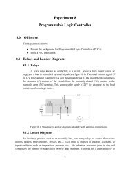
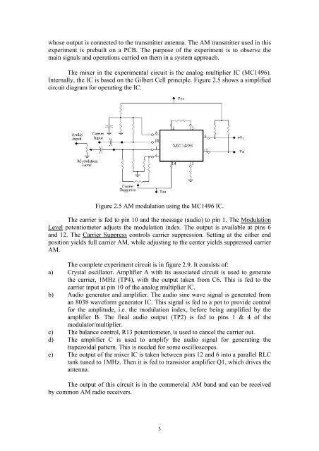
The mixer in the experimental circuit is the analog multiplier IC (MC1496).<br />
Internally, the IC is based on the Gilbert Cell principle. Figure 2.5 shows a simplified<br />
circuit diagram for operating the IC.<br />
Figure 2.5 <strong>AM</strong> modulation using the MC1496 IC.<br />
The carrier is fed to pin 10 <strong>and</strong> the message (audio) to pin 1. The <strong>Modulation</strong><br />
Level potentiometer adjusts the modulation index. The output is available at pins 6<br />
<strong>and</strong> 12. The Carrier Suppress controls carrier suppression. Setting at the either end<br />
position yields full carrier <strong>AM</strong>, while adjusting to the center yields suppressed carrier<br />
<strong>AM</strong>.<br />
The complete experiment circuit is in figure 2.9. It consists of:<br />
a) Crystal oscillator. Amplifier A with its associated circuit is used to generate<br />
the carrier, 1MHz (TP4), with the output taken from C6. This is fed to the<br />
carrier input at pin 10 of the analog multiplier IC.<br />
b) Audio generator <strong>and</strong> amplifier. The audio sine wave signal is generated from<br />
an 8038 waveform generator IC. This signal is fed to a pot to provide control<br />
for the amplitude, i.e. the modulation index, before being amplified by the<br />
amplifier B. The final audio output (TP2) is fed to pins 1 & 4 of the<br />
modulator/multiplier.<br />
c) The balance control, R13 potentiometer, is used to cancel the carrier out.<br />
d) The amplifier C is used to amplify the audio signal for generating the<br />
trapezoidal pattern. This is needed for some oscilloscopes.<br />
e) The output of the mixer IC is taken between pins 12 <strong>and</strong> 6 into a parallel RLC<br />
tank tuned to 1MHz. Then it is fed to transistor amplifier Q1, which drives the<br />
antenna.<br />
The output of this circuit is in the commercial <strong>AM</strong> b<strong>and</strong> <strong>and</strong> can be received<br />
by common <strong>AM</strong> radio receivers.<br />
3