Surgil ESIA Report - Volume III - EKN
Surgil ESIA Report - Volume III - EKN
Surgil ESIA Report - Volume III - EKN

Create successful ePaper yourself
Turn your PDF publications into a flip-book with our unique Google optimized e-Paper software.
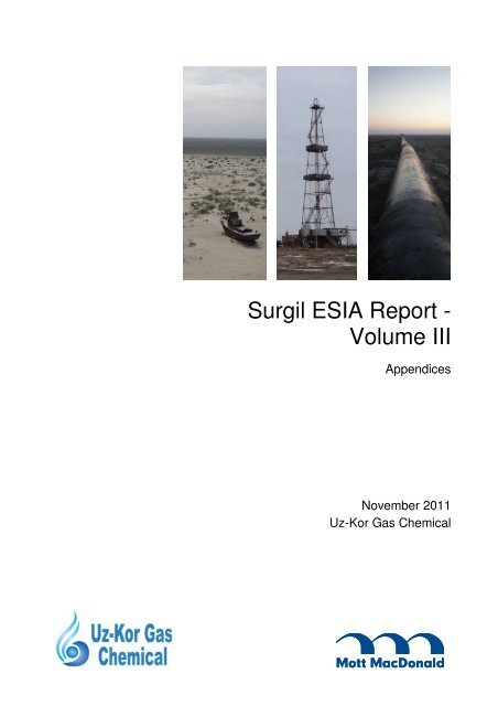
<strong>Surgil</strong> <strong>ESIA</strong> <strong>Report</strong> -<br />
<strong>Volume</strong> <strong>III</strong><br />
Appendices<br />
November 2011<br />
Uz-Kor Gas Chemical
<strong>Surgil</strong> <strong>ESIA</strong> <strong>Report</strong> -<br />
<strong>Volume</strong> <strong>III</strong><br />
265718 RGE GEV 08 C<br />
P:\Glasgow\GBD\RGE\GEV\Projects\254793 <strong>Surgil</strong> <strong>ESIA</strong>\9.0 Working<br />
Files\<strong>ESIA</strong> <strong>Report</strong>\Rev C - Responses to ADB and AECOM<br />
04 February 2011<br />
Appendices<br />
November 2011<br />
Uz-Kor Gas Chemical<br />
12th Floor, International Business Centre, 107B Amir Temur Str., Tashkent, Uzbekistan
<strong>Surgil</strong> <strong>ESIA</strong> <strong>Report</strong> - <strong>Volume</strong> <strong>III</strong><br />
Issue and revision record<br />
Revision Date Originator Checker Approver Description<br />
A 28/06/2011 R. Watson L. Chapman D Boyland Draft for comments<br />
B 03/08/2011 Tom Streather L. Chapman D Boyland Draft for Disclosure<br />
C 08/11/2011 Tom Streather L. Chapman D Boyland Final<br />
This document is issued for the party which commissioned it<br />
and for specific purposes connected with the above-captioned<br />
project only. It should not be relied upon by any other party or<br />
used for any other purpose.<br />
We accept no responsibility for the consequences of this<br />
document being relied upon by any other party, or being used<br />
for any other purpose, or containing any error or omission which<br />
is due to an error or omission in data supplied to us by other<br />
parties<br />
This document contains confidential information and proprietary<br />
intellectual property. It should not be shown to other parties<br />
without consent from us and from the party which<br />
commissioned it.
<strong>Surgil</strong> <strong>ESIA</strong> <strong>Report</strong> - <strong>Volume</strong> <strong>III</strong><br />
Content<br />
Chapter Title<br />
Page<br />
Appendix A. Supplementary Project Information______________________________________________________ 1<br />
Appendix B. Cuttings Management Procedure ______________________________________________________ 17<br />
Appendix C. National EIA’s _____________________________________________________________________ 65<br />
Appendix D. Permits _________________________________________________________________________ 324<br />
Appendix E. Public Consultation and Disclosure Plan _______________________________________________ 363<br />
Appendix F. Press Releases___________________________________________________________________ 401<br />
Appendix G. Public Exhibition Photoreports _______________________________________________________ 406<br />
Appendix H. Ecology – Bird Migration <strong>Report</strong> ______________________________________________________ 444<br />
Appendix I. Ecology – Texnet <strong>Report</strong> ___________________________________________________________ 459<br />
Appendix J. Ecology – Botanical <strong>Report</strong>__________________________________________________________ 501<br />
Appendix K. Ground Conditions Survey __________________________________________________________ 589<br />
Appendix L. Glossary of Acoustic Terms _________________________________________________________ 648<br />
Appendix M. Consultation Records ______________________________________________________________ 651<br />
Appendix N. Air Quality _______________________________________________________________________ 696<br />
Appendix O. DQRA __________________________________________________________________________ 702<br />
254793/RGE/GEV/03/01/08/11/2011<br />
6
<strong>Surgil</strong> <strong>ESIA</strong> <strong>Report</strong> - <strong>Volume</strong> <strong>III</strong><br />
Appendix A.<br />
Supplementary Project<br />
Information<br />
A.1.<br />
Overview<br />
The following section provides additional project information that is intended to supplement the project<br />
description provided in Chapter 2 of <strong>Volume</strong> II. It provides further technical details of key upstream and<br />
downstream (UGCC) component processes of the Project which have been used to inform the <strong>ESIA</strong>.<br />
A.2.<br />
A.2.1.<br />
Upstream Component – <strong>Surgil</strong> Field<br />
Well Design<br />
Production wells will target production from the <strong>Surgil</strong> Field gas-condensate reserves contained within<br />
Terrigenous deposits of the Middle Jurassic (J 2 ) and Upper Jurassic (J 3 ). Sixteen productive zones (seams)<br />
are contained within these deposits (5 Upper Jurassic and 11 Middle Jurassic seams), in depths between<br />
1,590 metres and 3,006 metres. The <strong>Surgil</strong> Field gas-condensate wells are a vertical design with a<br />
maximum depth of 2,950 metres.<br />
A.2.1.1. Well Casing<br />
Wells are drilled in sequence through various geological strata. Once each well section of the hole is<br />
drilled, well casing is installed in the hole to provide structural integrity to the wellbore, and where<br />
necessary isolate any high pressure zones from each other and from the surface. Well casing is important<br />
as it provides a conduit to allow hydrocarbons to be extracted without intermingling with other fluids and<br />
formations. It is instrumental in preventing blowouts allowing the formation to be sealed in the event of a<br />
‘blowout’. Deeper well sections are drilled once the previous section above is cased and this continues<br />
until the gas-condensate production zone is reached.<br />
The type of casing depends on the sub-surface characteristics of the well. Typically there are four different<br />
types of casing. Table A.1 provides the casing design for a typical <strong>Surgil</strong> Field well, including a description<br />
of the purpose of the different casing type.<br />
254793/RGE/GEV/03/01/03/08/2011<br />
1
<strong>Surgil</strong> <strong>ESIA</strong> <strong>Report</strong> - <strong>Volume</strong> <strong>III</strong><br />
Table A.1: Casing Design for Typical <strong>Surgil</strong> Field Well<br />
Casing Type<br />
Casing Interval<br />
Depth<br />
Casing<br />
Diameter<br />
Description<br />
Conductor 0 – 9 m 53.0 cm (20.9”) Installed first and is typically cemented into place. It serves as a<br />
support during drilling operations, and to prevent collapse of any<br />
loose soil near the surface.<br />
Surface<br />
Casing<br />
Intermediate<br />
Casing<br />
Production<br />
Casing<br />
Source: Uz-Kor<br />
0 – 50 m 42.6 cm (16.8”) Installed below conductor, the primary purpose of surface casing is<br />
to protect any freshwater deposits near the surface of the well from<br />
being contaminated by leaking hydrocarbons or salt water from<br />
deeper underground. It also serves as a conduit for drilling mud<br />
returning to the surface. The thickness of the casing is determined<br />
to ensure that there is little or no possibility of freshwater<br />
contamination. Like conductor casing it is cemented into place<br />
50 – 400 m 29.8 cm (11.7”)<br />
400 – 1,500 m 21.9 cm (8,6”)<br />
Intermediate casing is the longest section and is designed to<br />
minimise hazards from any known or unknown surface formations<br />
that might contaminate the well. For <strong>Surgil</strong> wells the intermediate<br />
casing will isolate Noegene-Quaternary and Cretaceous deposits<br />
which are prone to formation caving.<br />
1,500 – 2,950 m 14.0 cm (5.5”) Production casing is installed last and is the deepest section of<br />
casing in a well. This casing provides a conduit from the petroleum<br />
producing formation to the surface of the well.<br />
Cement is commonly placed between the outside of the casing and the borehole to set the casing. The<br />
cementing intervals for a typical <strong>Surgil</strong> well will be the following:<br />
0 – 50m;<br />
0 – 400m;<br />
0 – 1,300m;<br />
1,300 – 1,500m;<br />
0 – 1,450m; and<br />
1,450 – 1,950m<br />
A.2.1.2. Well Completion and Control<br />
Once the casing has been set proper lifting equipment is installed. The well is then ‘completed’ according<br />
to the requirements and type of gas. Completion is the process in which the well is enabled to produce the<br />
gas-condensate.<br />
The wellhead consists of the pieces of equipment mounted at the opening of the well to manage the<br />
extraction of hydrocarbons. The wellhead consists of three components, the casing head, the tubing seal<br />
and the ‘Christmas tree’ which is the most visible part and typically about 6’ in height. Figure A.1 provides<br />
an example of a typical wellhead for the <strong>Surgil</strong> Field. The wellhead has the following functions:<br />
Prevention of outflow of gas should there be a failure in the integrity of the well casing and also to<br />
provide protection of the well against excesses of pressure through installation shutoff;<br />
Allow short-term diversion of gas stream to wellhead flare during periods of maintenance;<br />
Allow well closure in the event of an emergency situation.<br />
254793/RGE/GEV/03/01/03/08/2011<br />
2
<strong>Surgil</strong> <strong>ESIA</strong> <strong>Report</strong> - <strong>Volume</strong> <strong>III</strong><br />
Figure A.1: <strong>Surgil</strong> Field Wellhead<br />
Source: MML<br />
Well control equipment is sited at a minimum distance of 25m from the well and flares for abnormal<br />
operation / maintenance periods are provided at a minimum distance of 100m from the wells.<br />
A.2.2.<br />
Drilling Muds<br />
The drilling process will use drilling fluids/muds to remove drilled cuttings (rock chippings) from the wellbore<br />
and control of formation pressures. The drilling fluids will also seal permeable formations, maintain well<br />
bore stability, cool and lubricate the drill bit, and transmit hydraulic energy to the drilling tools and bit.<br />
Both water-based drilling fluids (WBDF) and non-aqueous based fluids (NABF) (with bentonite clays as a<br />
thickener) will be utilised. WBDF will be used for the first 50m of the well bore and NABF for depths below<br />
50m. The use of NABF is required due to the geological characteristics of the ground through which the<br />
drilling will advance, with the NADF acting as a greasing additive to improve the drilling process by<br />
reducing freeze-in danger, increase chisel operating efficiency and decrease hydraulic resistance.<br />
Additional reagents, including caustic and ash soda, graphite and other reagents, will be added as required<br />
to achieve the required properties for drilling depending on the nature of the strata through which the well<br />
bore is being advanced.<br />
Table A.2 provides a summary of the drilling mud components to be used for a <strong>Surgil</strong> well, by well interval.<br />
254793/RGE/GEV/03/01/03/08/2011<br />
3
<strong>Surgil</strong> <strong>ESIA</strong> <strong>Report</strong> - <strong>Volume</strong> <strong>III</strong><br />
Table A.2: <strong>Surgil</strong> Well Typical Drill Mud Components<br />
Well Interval (m) Mud Type Mud Components<br />
From<br />
To<br />
9 50 WBDF Clay Polymer; Bentonite; Soda Ash; Caustic Soda; K-4<br />
50 400 NABF Clay Polymer; Bentonite; Soda Ash; Caustic Soda; K-4, Oil<br />
400 1,500 NABF Clay Polymer; Mud Powder; Soda Ash; Caustic Soda; K-4, KMTs-600, Oil, Graphite<br />
Silver<br />
1,500 2,950 NABF Lignosulphonatic; Mud Powder; Soda Ash; Caustic Soda; K-4; KLMs-600;<br />
Ferrocromelignosulphonate; Oil; Graphite Silver<br />
Source: Uk-Kor<br />
The required volumes of the above mud components per <strong>Surgil</strong> well is summarised in Table A.3.<br />
Table A.3: Predicted Amount of Drill Mud Components per <strong>Surgil</strong> Well<br />
Mud Component<br />
Total Tonnes per Well<br />
Bentonite 24.3<br />
Clay 64.9<br />
Soda Ash 6.9<br />
Caustic Soda 4.3<br />
K-4 37.4<br />
KMTs-600 5.6<br />
Ferrocromelignosulphonate 7.8<br />
Oil 27.3<br />
Graphite Silver 2.7<br />
Source: Uz-Kor<br />
A.2.3.<br />
Gas and Condensate Composition<br />
Table A.4and Table A.5 provide the design case composition of gas and condensate feedstock from the<br />
<strong>Surgil</strong> and East Berdakh Fields, respectively.<br />
Table A.4: Composition of Natural Gas Received from Project Gas Fields<br />
Index<br />
<strong>Surgil</strong> Field East Berdakh Field<br />
(molar proportion, %) (molar proportion, %)<br />
CH 4 90,318 91,694<br />
C 2H 6 4,545 4,265<br />
C 3H 8 2,146 1,600<br />
iC 4H 10 0,286 0,268<br />
nC 4H 10 0,341 0,232<br />
C 5+ 0,340 0,216<br />
H 2O 0,005 0,005<br />
N 2 1,126 1,294<br />
CO 2 0,893 0,426<br />
Source: Duty Specification (GSP)<br />
254793/RGE/GEV/03/01/03/08/2011<br />
4
<strong>Surgil</strong> <strong>ESIA</strong> <strong>Report</strong> - <strong>Volume</strong> <strong>III</strong><br />
Table A.5: Composition of Condensate Received from Project Gas Fields<br />
Index<br />
<strong>Surgil</strong> Field East Berdakh Field<br />
(molar proportion, %) (molar proportion, %)<br />
CH 4 6,897 11,600<br />
C 2H 6 4,849 5,172<br />
C 3H 8 9,796 7,499<br />
iC 4H 10 2,908 3,070<br />
nC 4H 10 5,247 5,296<br />
C 5+ 69,872 67,026<br />
Н 2О 0,071 0,069<br />
N 2 0,008 0,028<br />
CO 2 0,352 0,240<br />
Н 2S 0,000 0,000<br />
A.2.4.<br />
Gas Gathering Stations<br />
Following extraction, gas and condensate are piped from the wells to one of six Gas Gathering Stations<br />
(GGS). Each site and configuration of the GGS will be slightly different; however each one will be<br />
equipped with a main inlet pipe collection block, an overload relief valve to protect against excess pressure,<br />
a flare for periods of abnormal operation, drainage facilities, lighting arrestors and an operator house. Each<br />
GGS will collect gas from 20 individual wells.<br />
The exact design and layout of the gas gathering system is based on the average operational production,<br />
expected field pressure of wells and also thermal and pressure conditions at the well heads. Each one will<br />
be developed in accordance with international construction norms and regulations. Table A.6 provides a<br />
summary of key features for a GSS.<br />
Once collected, the gas and condensate is transported via pipeline to the <strong>Surgil</strong> CGTU. Maximum distance<br />
from GGS to CGTU is 4km.<br />
Table A.6: Key features of GGS<br />
Infrastructure<br />
Dimensions<br />
Plot size (hectares) 0.14 – 0.20<br />
Building area (hectares) 0.03 – 0.04<br />
Building density (%) 20-25<br />
Area of flare facilities (hectares) 0.79<br />
Source: JSC “O” Zlitineftgaz – PFS “Complex <strong>Surgil</strong> Field construction with extraction of valuable components!”<br />
A.2.5.<br />
Complex Gas Treatment Unit<br />
Figure A.2: presents the <strong>Surgil</strong> CGTU Layout.<br />
254793/RGE/GEV/03/01/03/08/2011<br />
5
<strong>Surgil</strong> <strong>ESIA</strong> <strong>Report</strong> - <strong>Volume</strong> <strong>III</strong><br />
Figure A.2: Complex Gas Treatment Unit (CGTU) Layout<br />
Approximate location of new<br />
artesian wells<br />
Source: JSC “O’ZLITINEFTGAZ”, Complex development of <strong>Surgil</strong> Field With Extracting of Valuable Components, Feasibility Study, 2009<br />
254793/RGE/GEV/03/01/03/08/2011<br />
6
<strong>Surgil</strong> <strong>ESIA</strong> <strong>Report</strong> - <strong>Volume</strong> <strong>III</strong><br />
Figure A.3 and Figure A.4 depict some existing related facilities in the <strong>Surgil</strong> CGTU. The evaporation pond<br />
shown has recently been upgraded and has been sized to accommodate all planned wastewater flows from<br />
the full <strong>Surgil</strong> Field development.<br />
Figure A.3: Existing <strong>Surgil</strong> CGTU Evaporation Pond<br />
Figure A.4: Existing <strong>Surgil</strong> CGTU Flare<br />
Source: MML<br />
Source: MML<br />
A.2.6.<br />
Upstream - Camp Settlement<br />
Construction and operational workers camp for the CGTU and ancillary infrastructure works will be housed<br />
in the camp settlement being developed as part of the related facilities prior to this camp being utilised for<br />
operational staff. Whilst the camp is being developed, construction and operational staff will be housed in<br />
the existing UNG camp at Uchsay (under rental agreement). During periods of high construction activity<br />
additional temporary worker camp facilities will be provided to accommodate construction workers on site.<br />
The <strong>Surgil</strong> Field camp settlement will be built 500 metres from the <strong>Surgil</strong> CGTU. The camp will be<br />
designed to comply with the requirements advocated by the IFC and EBRD guidance note “Workers’<br />
accommodation: processes and standards” dated August 2009. Key requirements of this will be outlined in<br />
the social management and mitigation plan. As a minimum, the camp will include the following:<br />
Living quarters for 72 people with a maximum of 4 people per room<br />
Medical facilities<br />
Kitchen and canteen facilities<br />
Leisure facilities including television and internet<br />
Ablutions<br />
Sauna<br />
Security checkpoint<br />
Typical example facilities (based on the Urga Field camp which is also in the Aral Sea basin) are presented<br />
in Figure A.5 to Figure A.10<br />
254793/RGE/GEV/03/01/03/08/2011<br />
7
<strong>Surgil</strong> <strong>ESIA</strong> <strong>Report</strong> - <strong>Volume</strong> <strong>III</strong><br />
Figure A.5: Laundry Facilities<br />
Figure A.6: On-site Ambulance<br />
Figure A.7:Kitchen Facilities<br />
Figure A.8: Food Storage Facilities<br />
Figure A.9: Medical Facilities and Doctor<br />
Figure A.10: Potable Water Storage<br />
Figure A.11 sets out the proposed layout of the camp settlement.<br />
254793/RGE/GEV/03/01/03/08/2011<br />
8
<strong>Surgil</strong> <strong>ESIA</strong> <strong>Report</strong> - <strong>Volume</strong> <strong>III</strong><br />
Figure A.11: Layout of the proposed <strong>Surgil</strong> CGTU Camp<br />
Source: JSC “O’ZLITINEFTGAZ”, Complex development of <strong>Surgil</strong> Field With Extracting of Valuable Components, Feasibility Study, 2009<br />
254793/RGE/GEV/03/01/03/08/2011<br />
9
<strong>Surgil</strong> <strong>ESIA</strong> <strong>Report</strong> - <strong>Volume</strong> <strong>III</strong><br />
A.3.<br />
A.3.1.<br />
Downstream Component – Ustyurt Gas Chemical Complex<br />
Introduction<br />
The new UGCC facility will be designed to receive natural gas and un-stabilised condensate via pipelines<br />
from the <strong>Surgil</strong> Field as well as from the North and East Berdakh Fields, which will then be processed to<br />
form high-density polyethylene (HDPE) and polypropylene (PP).<br />
As outlined in <strong>Volume</strong> II, the UGCC consists of a number of process activities culminating in the production<br />
of HDPE for the production of polyethylene pellets and HDPE for the production of HDPE pellets. These<br />
pellets, plus any associated sales gas, will then be exported to international and national markets. The key<br />
processes involved in the production of the above include and are illustrated in Table 2.9 of <strong>Volume</strong> II;<br />
Gas separation plant (GSP);<br />
Ethylene plant (EP);<br />
HDPE plant; and<br />
PP plant.<br />
The following sections provide further details of the processes undertaken within the above plants. Details<br />
of the supporting utilities and offsite (U&O) infrastructure are provided in <strong>Volume</strong> II.<br />
A.3.2.<br />
Gas Separation Plant<br />
The purpose of the Gas Separation Plant is to condition the gas stream and stabilize the condensate<br />
stream from the new pipelines, recover ethane (C2) from the feed gas and to separate out heavier<br />
components (C3-C4) and (C5+) as liquid petroleum gasoline, as well as methane (C1). The GSP plant will<br />
be designed for three cases relating to the average feedstock gas composition: Minimum, Maximum and<br />
Design.<br />
The GSP process flow diagram is illustrated in Figure A.12. The Gas Separation Plant includes a number<br />
of process units, as follows:<br />
Gas Inlet / Reception Facilities;<br />
Acid Gas Removal Unit (AGRU);<br />
Feed Gas Chilling, Dehydration and Mercury Removal Unit (MRU);<br />
Ethane Recovery Unit (ERU);<br />
Fractionation Unit;<br />
Condensate Treatment Unit;<br />
Export Gas Compression Unit; and<br />
Refrigeration System.<br />
The <strong>Surgil</strong> gas is considered ‘sweet’ as it does not contain any hydrogen sulphide and as such the GSP<br />
plant configuration does not require a hydrogen sulphide removal step.<br />
254793/RGE/GEV/03/01/03/08/2011<br />
10
<strong>Surgil</strong> <strong>ESIA</strong> <strong>Report</strong> - <strong>Volume</strong> <strong>III</strong><br />
Figure A.12: GSP Process Schematic<br />
Source: Technical Review <strong>Report</strong>, Nexant, Feb 2011<br />
A.3.2.1. Reception Facilities<br />
The volume of the combined feed gas from <strong>Surgil</strong> and East Berdakh Fields will be measured with a new<br />
inlet gas metering station. Downstream of the metering station, there will be a feed gas inlet filter<br />
separator, where entrained hydrocarbon liquids are separated from the feed gas and are routed to the<br />
Unstabilized Condensate Treatment Plant. The gas will then be re-compressed with a feed gas<br />
compressor and sent to Feed Gas Chilling, Dehydration & Mercury Removal Unit.<br />
A.3.2.2. Feed Gas Chilling, Dehydration and Mercury Removal Unit<br />
Molecular sieve technologies will be used for the dehydration and mercury removal process steps.<br />
Molecular sieves are adsorbents composed of aluminosilicate crystalline polymers (zeolites) which<br />
efficiently remove low concentrations of polar or polarisable contaminants such as water, methanol,<br />
hydrogen sulphide, carbon dioxide, COS, mercaptans, sulfides, ammonia, aromatics and mercury down to<br />
trace concentrations. Molecular sieves will also reduce water concentration to less than 1ppm which is<br />
necessary for further downstream processing.<br />
Mercury is typically removed to prevent risk of metal embitterment of downstream plant. The exact process<br />
design is not fully confirmed at this point and may include the mercury removal facility being placed after<br />
the dehydration unit, or combined with the dehydration unit.<br />
254793/RGE/GEV/03/01/03/08/2011<br />
11
<strong>Surgil</strong> <strong>ESIA</strong> <strong>Report</strong> - <strong>Volume</strong> <strong>III</strong><br />
A.3.2.3. Ethane Recovery Unit<br />
NGL and LPG liquids recovery will be undertaken through use of low temperature turbo-expander<br />
technology which is currently the most efficient process for obtaining high ethane and propane recoveries.<br />
The ERU plant will produce the following streams:<br />
Sales gas (mainly methane) sent to Export Gas Compression Unit;<br />
Ethane gas sent to Acid Gas Removal Unit; and<br />
Residue gas (C3+) sent to Fractionation Unit.<br />
In general, the plant will consist of the following key equipment:<br />
Cold Box<br />
Turbo Expander<br />
Turbo Expander Brake Compressor<br />
Recycle Gas Compressor<br />
Demethaniser<br />
Deethaniser<br />
Deethaniser Reboiler<br />
The demethaniser will strip all methane from the condensed liquid and produce a methane-free stream at<br />
the bottom of the tower. This will contain most of the recovered ethane and heavier components. The liquid<br />
from the bottom of demethaniser will be pumped and heated through exchangers before being introduced<br />
to the deethaniser to produce purified ethane from the column overhead which is then routed to the acid<br />
gas removal unit.<br />
A.3.2.4. Fractionation Unit<br />
Within the fractionation unit the LPG stream and C5 products or heavier will be fractionated from the ERU<br />
residue stream containing C3 products or heavier.<br />
A.3.2.5. Acid Gas Removal Unit<br />
In the AGRU, acid gases (generally CO 2 and hydrogen sulphide (if any)) are removed using amine<br />
adsorption from the ethane stream recovered in the ERU. Removal of acid gases serves to avoid a<br />
reduction in heating value due to excess CO 2 and limits CO 2 freezing on exchanger surfaces in the<br />
demethaniser, which is known to reduce the efficiency of the process and block heat exchangers.<br />
The removal of CO 2 from the ethane stream is carried out by a chemical reaction which occurs between the<br />
amine solution and the acid gases. This occurs in an absorption column where the gas contacts the amine<br />
solution. The second stripper column separates absorbed acid gases from the amine solution. The acid<br />
gas produced from stripper will be flared as it does not contain hydrogen sulphide.<br />
A.3.2.6. Condensate Treatment Unit<br />
Within the Condensate Treatment Unit, the condensate stream is stabilised in a flash drum to remove light<br />
hydrocarbons (mainly methane) which is then routed to the reception facilities. In addition, a heavier<br />
hydrocarbon stream is routed to a condensate stabiliser, where LPG is separated from C5+ material. LPG<br />
product is recovered from the top of the condensate stabiliser and routed to ethylene plant, whilst the<br />
bottom product, consisting mainly of C5 products or heavier, is mixed with the NGL product and routed to<br />
ethylene plant for further processing.<br />
254793/RGE/GEV/03/01/03/08/2011<br />
12
<strong>Surgil</strong> <strong>ESIA</strong> <strong>Report</strong> - <strong>Volume</strong> <strong>III</strong><br />
A.3.2.7. Export Gas Compression Unit<br />
The export gas compression unit will consist of a reciprocating export gas compressor which will export out<br />
the sales gas (mainly methane) from the plant’s battery limits.<br />
A.3.3.<br />
Ethylene Plant<br />
Ethane, LPG and NGL is delivered from the GSP via pipeline to the ethylene plant for production of high<br />
purity ethylene and smaller amounts of propylene. The plant process will involve use of steam cracking<br />
technology (thermal pyrolysis in the presence of steam) and reaction temperatures in the steam cracker will<br />
be around 850 º C.<br />
Within the steam cracking plant the saturated hydrocarbons are converted to smaller, often unsaturated<br />
hydrocarbons, with ethylene as the key product. This plant will produce approximately 387 KTA of polymer<br />
grade ethylene and 82 KTA of polymer grade propylene. Modern steam crackers such as those to be used<br />
in this process ensure a short reaction time that improves yield and minimises the production of associated<br />
by-products.<br />
After the cracking temperature has been reached the gas is quickly quenched in the recovery section (coldend)<br />
of the plant to stop the reaction in a transfer line heat exchanger. This process also recovers and<br />
separates the olefin products produced and recycles saturated hydrocarbons to cracking. The recovery<br />
section includes:<br />
A compression unit to compress the cracked gas for the fractionation of hydrocarbon;<br />
Caustic-washing in a caustic tower to remove acid gases, and<br />
Drying prior to carrying out low temperature separation.<br />
Separation of products will be conducted using demethaniser, deethaniser and depropaniser columns in a<br />
sequence tailored to the feedstock being cracked.<br />
In addition to the recovery of ethylene and propylene, the chilling train of the ethylene plant will produce a<br />
mixed light hydrocarbon stream, hydrogen, pyrolysis gasoline and pyrolysis oil. The light hydrocarbon<br />
stream is recycled to the plant furnace and cracked to extinction whilst the gasoline and oil is pumped to<br />
the plant site boundary for export.<br />
The steam cracking process results in the slow deposition of coke and de-coking is required every few<br />
months. De-coking requires the furnace to be isolated and then a flow of steam or a steam / air mixture is<br />
passed through the furnace coils. This converts the hard solid carbon layer to CO and CO 2 which are<br />
vented to atmosphere.<br />
The ethylene and propylene products of the ethylene plant, together with butene-1 and hydrogen are then<br />
fed to two separate processes:<br />
HDPE plant for the production of polyethylene pellets; and<br />
PP plant for the production of PP pellets.<br />
254793/RGE/GEV/03/01/03/08/2011<br />
13
<strong>Surgil</strong> <strong>ESIA</strong> <strong>Report</strong> - <strong>Volume</strong> <strong>III</strong><br />
A.3.4.<br />
HDPE Plant<br />
A.3.4.1. Overview<br />
HDPE will be produced by catalytic polymerisation of ethylene in bimodal slurry (suspension) reactors. The<br />
ethylene, propylene and hydrogen processed in the ethylene plant will feed the HDPE plant to produce a<br />
guaranteed 30 tonnes per hour (per train) of HDPE pellets along two trains.<br />
The HDPE plant can produce varying grades of polymer and includes the following components as outlined<br />
in Figure A.13<br />
Catalyst Preparation Section;<br />
Polymerization Section;<br />
Separation and Drying Section;<br />
Pelletizing, Storage and Packing Section;<br />
Solvent Recovery Section; and<br />
Process Auxiliary Section.<br />
Figure A.13: HDPE process overview<br />
Source: Technical Review <strong>Report</strong>, Nexant, Feb 2011<br />
254793/RGE/GEV/03/01/03/08/2011<br />
14
<strong>Surgil</strong> <strong>ESIA</strong> <strong>Report</strong> - <strong>Volume</strong> <strong>III</strong><br />
A.3.4.2. HDPE Process<br />
The HDPE process employs stirred-tank reactors in series. The polymerisation reactors include provision<br />
for reaction and a mechanical stirrer to ensure uniform mixing, and the reactor system operates in a<br />
continuous mode with a cascade of two or three reactors.<br />
The reactor system is charged with polymerisation grade ethylene, recycle and make-up hexane diluent,<br />
hydrogen, comonomer, catalyst and an activating agent. Ethylene, comonomor, dehydrated hexane and<br />
catalyst are continuously fed to the reactors. Hydrogen, propylene and butene-1 are continuously<br />
premixed with gas and fed to the recycle line leading to the reactors.<br />
The polymer slurry leaving the final polymerisation reactor is depressurised into a flash vessel where<br />
unconverted ethylene is vaporised from the solvent and collected for recycle. The flashed slurry is fed to a<br />
centrifuge where the polymer cake is separated from the hexane diluent. The wet polymer is then fed to<br />
the dryer and dried to yield a polymer powder which can be compounded and pelletised.<br />
Hexane recovered from the centrifuge is combined with hexane vapour liberated in the drying operation. It<br />
is then sent to either the polymerisation section or to the solvent recovery system where the hexane is<br />
distilled and re-circulated to the polymerisation reactors. A low quantity (circa 500 ton/yr) of low molecular<br />
weight polymers will be generated as a by-product wax which can be recycled back to the ethylene plant.<br />
The polyethylene powder is combined with additives and processed in a compounding extruder. Pellets<br />
are then produced in an underwater pelletiser. Finally the product pellets are pneumatically conveyed to<br />
bagging silos by a pellet transfer blower.<br />
A.3.5.<br />
PP Plant<br />
A.3.5.1. Overview<br />
The ethylene, propylene and hydrogen processed in the ethylene plant will feed the PP plant to produce PP<br />
pellets. The guaranteed production design capacity will be 16 ton/hr. A bulk reactor system will be used to<br />
enable the polymerisation of homopolymer and random copolymer, followed by a gas phase reactor system<br />
for the sequential production of impact copolymer. As such, the plant is to be designed but not limited to<br />
produce the following products:<br />
Homopolymer;<br />
Random copolymer; and<br />
Impact copolyemer.<br />
The PP plant includes units described below, as outlined in Figure A.14:<br />
Catalyst preparation and feeding;<br />
Prepolymerisation and polymerisation;<br />
Degassing and monomer recovery;<br />
Copolymerisation;<br />
Polymer finishing;<br />
Blowdown and process auxiliaries;<br />
Monomer treating; and<br />
Pelletising, storage and packing system.<br />
254793/RGE/GEV/03/01/03/08/2011<br />
15
<strong>Surgil</strong> <strong>ESIA</strong> <strong>Report</strong> - <strong>Volume</strong> <strong>III</strong><br />
A.3.5.2. PP Process<br />
The PP plant consists of a single train made up of a catalyst feed system and a reactor system followed by<br />
monomer flash, recycling, stripping, and polymer finishing and handling.<br />
With reference to Figure A.14, the plant will include a series of two reactor systems for homopolymer and<br />
impact copolymer production. The first reactor system is comprised of two loop type reactors operating in<br />
series followed by one fluid-bed gas phase reactor as the second reactor system.<br />
The bulk polymeriser has a residence time of about 1 to 1.5 hours which will produce about 50%<br />
conversion per pass of propylene. The gas phase fluidised bed reactor has a 0.5 – 1.0 hour residence<br />
time.<br />
The polymer leaving the flash tank is purged with steam at the condenser to recover the residual monomer<br />
and to deactivate the remaining catalyst. The polymer powder is then sent to the downstream powder<br />
storage and finishing sections where the powder and stabilisers are homogenised, extruded and pelletised.<br />
Pellets are dehydrated, dried and separated from coarse and fine and then transferred to silos.<br />
HP and LP blowdown systems plus a guard cyclone are provided for emergency flare relief, the latter of<br />
which prevents polymer entrainment to flare.<br />
Figure A.14: Schematic of Generic PP process<br />
Source: Technical Review <strong>Report</strong>, Nexant, Feb 2011<br />
254793/RGE/GEV/03/01/03/08/2011<br />
16
<strong>Surgil</strong> <strong>ESIA</strong> <strong>Report</strong> - <strong>Volume</strong> <strong>III</strong><br />
Appendix B. Cuttings Management<br />
Procedure<br />
This Appendix includes a translation of the Uz-Kor drill cuttings and muds management procedure.<br />
254793/RGE/GEV/03/01/03/08/2011<br />
17
Management procedure of the drilling wastes<br />
(cuttings barns) recycling, generated during<br />
production wells drilling in <strong>Surgil</strong> field<br />
CONTENTS<br />
1. Introduction . . . . . . . . . . . . . . . . . . . . . . . . . . . . . . . . . . . . . . . . . . . . . . . . . . . . . . . . . . . . . . . 3<br />
2. Work objective. . . . . . . . . . . . . . . . . . . . . . . . . . . . . . . . . . . . . . . . . . . . . . . . . . . . . . . . . . . . . 5<br />
3. Field of application . . . . . . . . . . . . . . . . . . . . . . . . . . . . . . . . . . . . . . . . . . . . . . …. . . . . . . . . 6<br />
4. Normative references and analysis of the current legislation of the Republic of Uzbekistan<br />
concerning drilling wastes recycling . . . . . . . . . . . . . . . . . . . . . . . . . …………. . . . . . . . . 7<br />
5. Review of library materials, literature, patent designs and other content on existing drilling<br />
wastes recycling technologies and practice in the territory of the Republic of Uzbekistan . . 10<br />
6. Ustyurt region geographic-climatic features data review . ……………………………... . . . 13<br />
7. Analysis of drilling mud design composition and parameters. Definition of drilling mud<br />
and formed drilling cuttings danger class ………………………………….. . . . . . . . . . . . .<br />
. . . . . 16<br />
8. Recycling technology of the drilling wastes (cuttings barns) of the <strong>Surgil</strong> field production<br />
wells………………………………. . . . . . . . . . . . . . . . . . . . . . . . . . . . . . . . . . . . . . . . . . . . . 19<br />
Appendix 1. Master plan of the design production wells position in <strong>Surgil</strong> field and order of<br />
their commissioning……………………………………………….. . . . . . . . . . . . . . . . . . . . . . . . 28<br />
Appendix 2. Generated drilling wastes amount calculation in accordance with wells design developed<br />
by group working draft for wells construction throughout <strong>Surgil</strong> field... …….... . . . . . . 30<br />
Appendix 3. Calculation of liquid evaporation thickness from surface layer in the region of<br />
<strong>Surgil</strong> field . . 32<br />
Appendix 4. Calculation of drilling mud danger/toxicity class used during wells construction in<br />
accordance with group working draft for <strong>Surgil</strong> field . . . . . . . . . . . . . . . . . . . . . . . . . . . . . . . . . . 35<br />
Appendix 5. Drilling cuttings (cuttings barns) neutralization technology containing oily soils<br />
(grounds) ……………………………………………………….. . . . . . . . . . . . . . . . . . . . . . . . . . 46<br />
- 2 -
“Management of Ustyurt GCC infrastructure objects<br />
and <strong>Surgil</strong> GCF construction” UE »<br />
1. INTRODUCTION<br />
1.1. Oil and gas wells drilling is connected with formation of considerable volumes of wastes to<br />
which concern drilling mud, drilling cuttings or drilling rock, drilling mud-polluted drilling sewage<br />
wastes, chemical reagents, oil products. Chemical reagents in the drilling mud, containing in the<br />
structure a broad spectrum of the mineral and organic nature substances, can impact on the biosphere<br />
objects during their ingress in environment.<br />
1.2. Drilling mud carry out various functions: washout, drilling rock lifting, heat removal from chisel,<br />
maintenance of wells walls integrity, lessening of drill pipes friction on well walls, etc. One of<br />
the basic components of any drilling mud is always bentonite (Montmorillonite clay). Effect of this<br />
component is explained by features of its physical and chemical nature, interaction with the disperse<br />
medium with formation of stable colloid system in it.<br />
1.3. Surface-active substance (SAS) concern to the reagents decreasing surface tension on threephase<br />
border "layer-water-oil". Main purpose of SAS is maintenance of the collectors’ natural permeability.<br />
Their penetration into drilling mud sharply reduces wells productivity and considerably<br />
extends their adaptation terms. There are used various substances as SAS: sulfanole, disolvane, carbozoline,<br />
stearox, azolyte and various oxy-ethylated spirits. Imperfection of SAS is their intensive<br />
adsorption at solid phase of drilling mud and also intensive foaming.<br />
1.4. There are uses reagents-defoaming for degassing of the drilling mud: soastoc, carbolineum, fusel<br />
oil, polymethylsilosales, solid oil, synthetic fatty acids, etc. There are uses reagents- fluid loss<br />
reducer for drilling mud quality maintenance (coal-alkali reagent, carboxymethyl cellulose, condensed<br />
the sulfite-spirit slop, hydrolyzed polyacrylimide) and thinning agents (ferrochrome lignosulfonate,<br />
nitrolignin, sunil, igetane).<br />
1.5. Besides, there are applied: thermal stabilizers, amendments, lubricant additives, emulsifying<br />
agents and other components. There is applied caustic soda all over the world as practically unique<br />
reagent – alkalinity controller. Caustic soda (NaOH) is colorless crystal mass, well water-soluble<br />
with large quantity heat release. Small alkali additives cause temporary clay particles dispersion,<br />
electrokinetic potential increase and, as consequence of it, decrease in drilling mud viscosity and<br />
fluid loss.<br />
1.6. Apparently from the aforesaid, drilling mud toxicity level depends on presence in its composition<br />
of the various organic and mineral components added in mud for giving to it those or other<br />
properties demanded at drilling. Drilling cuttings and drilling sewage waters acquire toxicity owing<br />
to contact with drilling mud. During ingress in environment the drilling mud and drilling cuttings<br />
cause local changes of the ecosystems chemical and biological parameters.<br />
1.7. This Management Procedure is developed for drilling wastes recycling during production wells<br />
construction in <strong>Surgil</strong> field and corresponds to uniform rules and requirements producible by laws<br />
of the Republic of Uzbekistan, and also to the international rules in relation to environmental protection<br />
during overland wells drilling, to their moving, warehousing and drilling wastes storage.<br />
- 3 -
Management procedure of the drilling wastes<br />
(cuttings barns) recycling, generated during<br />
production wells drilling in <strong>Surgil</strong> field<br />
2. WORK OBJECTIVE<br />
Management Procedure objective is:<br />
2.1. Studying of the legislative acts and regulations of the Republic of Uzbekistan on storage, recycling<br />
and disposal of the wastes generated during drilling.<br />
2.2. Data review on geographical and climatic features of Ustyurt region and analysis of drilling<br />
sites condition for the purpose of studying of drilling wastes disposal possibility immediately in cuttings<br />
storage barns provided by wells drilling working drafts.<br />
2.3. Analysis of library materials, literature, patent designs and other content on drilling wastes neutralization<br />
and giving recommendations about drilling wastes neutralization generated during production<br />
wells construction in <strong>Surgil</strong> field.<br />
2.4. Definition of drilling mud danger class recommended for drilling by the Group working draft<br />
for production wells construction in <strong>Surgil</strong> field, and also carrying out of experiments for detection<br />
of probable danger class of the drilling cuttings (waste drilling mud plus drilling rock).<br />
2.5. Technology engineering of drilling cuttings neutralization immediately in the drilling rig area in<br />
cuttings storage barn.<br />
2.6. Technology engineering of drilling cuttings neutralization/hardening immediately in the drilling<br />
rig area in cuttings storage barn.<br />
2.7. Technology engineering of neutralized/hardened drilling cuttings disposal immediately in the<br />
drilling rig area in cuttings storage barn provided by the Group working draft for production wells<br />
construction in <strong>Surgil</strong> field.<br />
2.8. Master plan of the design production wells position in <strong>Surgil</strong> field and order of their commissioning<br />
is presented in figure P1.1 and table P1.2 (Appendix 1).<br />
- 4 -
“Management of Ustyurt GCC infrastructure objects<br />
and <strong>Surgil</strong> GCF construction” UE »<br />
3. FIELD OF APPLICATION<br />
3.1. This Management Procedure establish uniform rules and order of carrying out of the technotechnological<br />
measures package directed to prevention of environmental pollution by the wastes,<br />
generated during drilling of production wells in <strong>Surgil</strong> field with use of drilling mud recommended<br />
by the Group working draft.<br />
3.2. This Management Procedure cover drilling cuttings neutralization and disposal (waste drilling<br />
mud plus drilling rock) and drilling sewage waters formed during wells drilling immediately in cuttings<br />
storage barns installed in the drilling rigs areas according to Group working draft for production<br />
wells construction in <strong>Surgil</strong> field.<br />
3.3. Cuttings storage barns used for temporary storage of drilling rock and waste drilling mud are a<br />
part of the drilling rig area developed scheme<br />
3.4. According to given by the customer project of wells design, formed on all wells of <strong>Surgil</strong> field<br />
drilling cuttings amount will make 29.7 thousand cubic meters, including 12.9 thousand cubic meters<br />
of drilling rock and 16.8 thousand cubic meters of WDM. Amount of formed DSW will make<br />
33.5 thousand cubic meters. Formed drilling cuttings amount calculations are resulted in Appendix<br />
2.<br />
3.5. Management Procedure is intended for industrial-engineering services of environmental protection<br />
of “Ustyurtgaz” USE.<br />
- 5 -
Management procedure of the drilling wastes<br />
(cuttings barns) recycling, generated during<br />
production wells drilling in <strong>Surgil</strong> field<br />
4. NORMATIVE REFERENCES AND ANALYSIS OF THE CURRENT<br />
LEGISLATION OF THE REPUBLIC OF UZBEKISTAN CONCERN-<br />
ING DRILLING WASTES RECYCLING<br />
4.1. According to the Law “On nature conservation” of the Republic of Uzbekistan, “Ustryurtgaz”<br />
USE obliged to conduct oil and gas operations effectively and safely, following the legislation of<br />
the Republic of Uzbekistan with observance of the working standards in the international oil and<br />
gas industry. Any possible negative environmental impacts, including atmospheric air, ground surface,<br />
interior, lakes, rivers, forests, flora and fauna, crops and other natural resources, should be minimized.<br />
4.2. List of the Republic of Uzbekistan’s Laws, Cabinet of Ministers’ Decisions and regulations of<br />
the Republic of Uzbekistan regulating enterprises activity in questions of environmental protection<br />
is presented below:<br />
Law of the RUz “On nature conservation” № 754-XII from December, 9. 1992 (with the following<br />
amendments).<br />
Law of the RUz “On flora protection and use” № 543-I from December, 26. 1997<br />
Law of the RUz “On especially protected natural territories” № 871-XII from May, 7. 1993<br />
Law of the RUz “On atmospheric air protection” № 353-I from December, 27. 1996<br />
Law of the RUz “On radiation safety» № 120-II from August, 31. 2000<br />
Law of the RUz “On environmental impact assessment” № 73-II from May, 25. 2000<br />
Law of the RUz “On water and water use» № 837-XII from May, 6. 1993<br />
Law of the RUz “On state land cadastre” № 666-I from August, 28. 1998<br />
Law of the RUz “On order of the Republic of Uzbekistan’s Land code consummation” №<br />
598-I from April, 30. 1998<br />
Law of the RUz “On wastes” № 362-P from April, 5. 2002<br />
Law of the RUz “On interior” № 444-P from December, 13. 2002<br />
Decision of Supreme Soviet “On consummation of the Republic of Uzbekistan’s Law “On<br />
interior” from September, 23. 1994<br />
<br />
<br />
<br />
<br />
Decision of OM of the RUz “On Regulations about the nature conservation State committee<br />
of the Republic of Uzbekistan” № 232-I from April, 26. 1996<br />
Decision of OM of the RUz “On approval of the Land code of the Republic of Uzbekistan”<br />
№ 599-I from April, 30. 1998<br />
Decision of CM of the RUz “On national strategy and program of the Republic of Uzbekistan<br />
on biological variety preservation” № 139 from April, 1. 1998 (with amendments).<br />
Decision of CM of the RUz “On approval of Regulations on order of creation and conducting<br />
of Uniform system of the state cadastres of the Republic of Uzbekistan” № 255 from July,<br />
17. 1996 (with amendments).<br />
Decision of CM of the RUz “On questions of the organization of activity of land resources<br />
State committee of the Republic of Uzbekistan” № 314 from July, 27. 1998<br />
Decision of CM of the RUz “On limited water use in the Republic of Uzbekistan” № 385<br />
<br />
<br />
<br />
from August, 3. 1993<br />
Decision of CM of the RUz “On approval of Regulations on order of development and conducting<br />
of state water cadastre of the Republic of Uzbekistan” № 11 from January, 7. 1998<br />
(with amendments).<br />
Decision of CM of the RUz “On approval of the rates for calculation of the collection<br />
amount for damage caused to flora of the Republic of Uzbekistan” № 293 from July, 27.<br />
1995<br />
Decision of CM of the RUz “On approval of statutory acts according to the Republic of Uzbekistan’s<br />
Law “On interior” № 19 from January, 13. 1997 (with amendments).<br />
- 6 -
“Management of Ustyurt GCC infrastructure objects<br />
and <strong>Surgil</strong> GCF construction” UE »<br />
<br />
<br />
<br />
<br />
<br />
<br />
Decision of CM of the RUz “On approval of the Regulations on order of conducting of state<br />
cadastre of especially protected natural territories of the Republic of Uzbekistan” № 104<br />
from March, 10. 1998<br />
Decision of CM of the RUz “On approval of the Regulations on order of creation and conducting<br />
of Uniform system of the state cadastres of the Republic of Uzbekistan” № 255<br />
from July, 17. 1996 (with amendments).<br />
Appendix № 1 to the decision of CM of the RUz “Regulations on order of allotments granting<br />
for mineral deposits development” № 20 from January, 13. 1996<br />
Appendix № 1 to the decision of CM of the RUz “Regulations on order of conducting of the<br />
state cadastre of flora objects of the Republic of Uzbekistan” № 343 from September, 5.<br />
2000<br />
Appendix № 1 to the decision of CM of the RUz “National strategy on decrease in greenhouse<br />
gases emission (fundamentals)” № 309 from October, 9. 2000<br />
Appendix № 2 to the decision of CM of the RUz “Measures for realization of National strategy<br />
for decrease in greenhouse gases emission” № 389 from October, 9. 2000<br />
4.3. Analysis of the currently in force acts and regulations in the territory of Republic of Uzbekistan<br />
show that:<br />
Enterprises, organizations, establishments, separate persons are obliged to introduce nonwaste<br />
and low-waste technologies, to reduce production and domestic wastes generation, to<br />
make their neutralization, processing, to observe rules of their sorting, warehousing, disposal<br />
and recycling. There is forbidden wastes storage and disposal on the settlements lands of nature-conservative,<br />
health-improving, recreational and historical and cultural purpose, within<br />
water protection zones and zones of water objects sanitary control, in other places where<br />
there can be danger to citizens’ life and health, and also especially protected natural territories<br />
and objects.<br />
Water protection zones are the protected natural territories adjacent to rivers’ channels, lakes,<br />
reservoirs, channels, collectors and other water objects. These zones are formed with a view<br />
of prevention of pollution, contamination, desiccation and silting of water objects by products<br />
of soils erosion, and also for maintenance of the favorable water regime.<br />
Wastes disposal in interior is supposed in exceptional cases by results of special researches<br />
with observance of requirements on maintenance of citizens’ life and health security, environmental<br />
safety, natural resources safety.<br />
Landfills for wastes neutralization and disposal should be placed according to hydrogeological<br />
conditions, as a rule, in sites with poorly filtering grounds (clay, loams, slates),<br />
with ground waters occurrence during their maximum lifting, taking into account water lifting<br />
during landfill operation, not less than 4m from the lower level of land-buried wastes.<br />
At placing of cards in grounds, characterized by filtration factor 10 -7 sm/s (for substances of I<br />
and II danger class), disposal of the toxic wastes is supposed without special measures for<br />
watertight diaphragms installation. There is provided watertight diaphragm at more permeable<br />
grounds or their instability (decompaction) to infiltrate.<br />
"Industrial wastes storages” construction is not supposed in the areas of fresh underground<br />
waters fields, in areas of influence of the centralized underground waters intakes, in areas<br />
underground waters discharge (thinning) in surface reservoirs and drains. "Industrial wastes<br />
storages” should be placing in the flood-free territories, formed by poorly filtering rocks<br />
with a glance of seasonal fluctuation of the ground waters level with its maximum occurrence.<br />
Departmental ecological monitoring of "industrial wastes storages” influence on environment<br />
is carried out by their owners. Water, air and soil sampling frequency from checking points<br />
for chemical analyses is determined by the enterprise by recommendation of bodies of<br />
- 7 -
Management procedure of the drilling wastes<br />
(cuttings barns) recycling, generated during<br />
production wells drilling in <strong>Surgil</strong> field<br />
Goskomprirody RUz. Wastes of I toxicity class is subject to obligatory processing and neutralization<br />
at specialized landfills before their disposal. State ecological monitoring over industrial<br />
wastes placement in "industrial wastes storages” is carried out by bodies of<br />
Goskomprirody RUz.<br />
4.4. Thus, on the basis of legislative acts and regulations analyses accepted in the Republic of Uzbekistan<br />
concerning to production wastes handling, it is possible to assert, that the drilling wastes<br />
disposal (waste drilling mud plus drilling cuttings) immediately in cuttings storages, developed according<br />
to the Group working draft for production wells construction throughout <strong>Surgil</strong> field, under<br />
condition of wastes conformity to <strong>III</strong> and to IV danger class - moderately and low-hazard wastes.<br />
- 8 -
“Management of Ustyurt GCC infrastructure objects<br />
and <strong>Surgil</strong> GCF construction” UE »<br />
5. REVIEW OF LIBRARY MATERIALS, LITERATURE, PATENT DE-<br />
SIGNS AND OTHER CONTENT ON EXISTING DRILLING WASTES<br />
RECYCLING TECHNOLOGIES AND PRACTICE IN THE TERRI-<br />
TORY OF THE REPUBLIC OF UZBEKISTAN<br />
5.1. Drilling cuttings represents a mix of drilling rock with drilling mud. Drilling rock by mineral<br />
composition, as a rule, is nontoxic, but, dispersing in medium of drilling mud processed by chemical<br />
reagents, its particles is adsorb toxic components on the surface and hereupon, also becomes<br />
pollutant of environment components.<br />
5.2. Waste drilling mud is a mud used in technological process and unsuitable for further drilling,<br />
and also, drilling mud and formation fluid, ejected from well onto earth surface during emergency<br />
flowing.<br />
5.3. Drilling sewage waters are the waters which have been acquired during well construction and<br />
equipment operation, representing drilling mud diluted with process water and atmospheric precipitation.<br />
5.4. Classification of WDM and DC by certain qualitative and quantitative characters has great importance<br />
for the decision of their recycling tasks. The most essential characters are the aggregative<br />
state, component composition and physiochemical properties.<br />
5.5. Specified wastes can be classified by their aggregative state as liquid (fluid), semi-fluid (pastelike)<br />
and hard. Thus, the basic character of their reference to this or that kind in the given classification<br />
is the content of hard and liquid phases. So, at the hard phase content to 35% the wastes keeps<br />
the mobility and fluidity and concerns to liquid wastes (WDM). At the hard phase content from 35<br />
to 85% the wastes has a paste-like view and concerns to semi-fluid (WDM with drilling cuttings).<br />
And, finally, at the liquid content in wastes composition less than 15% it is necessary to concern<br />
them to category of hard wastes (drilling rock or drilling cuttings). Wastes classification by such<br />
character allows reasonable approach to a choice of their transportation and mixture with other<br />
components method.<br />
5.6. Drilling wastes by component composition should be classified as clay, carbonate, haloidsulfate.<br />
This classification basically concerns to hard and semi-fluid wastes. Wastes which hard<br />
phase is presented by rocks of clay fraction (clay, mudstones, and marls) concern to clay. Carbonate<br />
are the wastes which hard phase mainly composed of carbonate rocks (limestone, dolomite). Haloid<br />
–sulfate wastes contains the hard phase basically composed of rock salt, gypsum and anhydrite.<br />
Such classification allows estimating suitability of these wastes as secondary raw materials at their<br />
recycling.<br />
5.7. Economic reasonability of this or that nature-conservative measure is defined at each concrete<br />
enterprise with a glance of its economic possibilities. Often construction of wastes neutralization<br />
units is non-value-added for one enterprise, as far as volumes of wastes generation are below the<br />
minimum capacities of the typical units which are manufactured by the industry.<br />
5.8. The decision of this problem should be or at regional level by construction of wastes processing<br />
units for all enterprises, or at local level by making of the units of low capacity for wastes neutrali-<br />
- 9 -
Management procedure of the drilling wastes<br />
(cuttings barns) recycling, generated during<br />
production wells drilling in <strong>Surgil</strong> field<br />
zation immediately on the sector objects. In this connection, it is necessary to carry the organization<br />
and maintenance of research and engineering developments of such units, creation of effective remedies<br />
and methods of wastes processing and neutralization to number of priorities both at regional<br />
level, and at level of the enterprises.<br />
5.9. Drilling wastes qualitative and quantitative composition is basic at a choice of their recycling<br />
method. Drilling wastes recycling technologies choice is carried out proceeding from principles of a<br />
state policy in the field of the handling with production and consumption wastes which is directed to<br />
reduction of wastes amount, their involving in economic circulation and fuller use of natural resources.<br />
5.10. Now the most known technologies of drilling wastes processing are based on the following<br />
methods:<br />
Thermal – incineration in open barns, furnaces of various types, reception of bituminous<br />
leavings.<br />
Physical – disposal in special burials, separation in a centrifugal field, vacuum filtering and<br />
filtering under pressure.<br />
Chemical – extraction by solvents, hardening with application (cement, liquid glass, clay)<br />
and organic (epoxy and polystyrene resins, polyurethanes, etc.) additives.<br />
Physiochemical - application of specially selected reagents changing physiochemical properties,<br />
with the following processing on the special equipment.<br />
Biological - microbiological decomposition in soil immediately in storage places, biothermal<br />
decomposition.<br />
Mechanical - drilling wastes pumping in lost circulation horizons.<br />
5.11. Now it is known about application of the following methods (and their combinations) of drilling<br />
wastes neutralization and processing:<br />
drilling cuttings incineration in the form of aqueous emulsions and recycling of released heat<br />
and gases;<br />
drilling cuttings dewatering or drying with return of oil products to production, and sewage<br />
waters in turnaround circulation and the following disposal of the hard leavings;<br />
drilling cuttings hardening by special consolidating compositions with the following use in<br />
other sectors of the national economy, or disposal in special landfills;<br />
drilling cuttings use as raw materials (components of other sectors of the national economy);<br />
drilling cuttings physiochemical separation (solvents, demulsifying agents, SAS, etc.) on<br />
component phases with the following use.<br />
5.12. Works basic directions in the field of semi-fluid drilling wastes neutralization (drilling cuttings<br />
and WDM hard phase) concentrate on physiochemical neutralization and hardening. A priority<br />
direction of neutralization is their hardening, realized by special hardeners.<br />
5.13. Neutralizing effect is achieved at the expense of drilling wastes transformation into the inert<br />
consolidated mass in which structure the basic polluting components are fixed. Such mass can be<br />
buried in lands for alignment of the lay of land, for filling in body of roads under construction, etc.,<br />
without environmental damage. Adding to wastes such active additives allows, besides, to receive<br />
hardened mass enduring a load which is created by the transport.<br />
5.14. Solid preservative matrix formed at hardening prevents dissolution of toxic substances under<br />
the influence of environment components, additionally fix them physically and chemically, reduces<br />
surface contact area with environment.<br />
- 10 -
“Management of Ustyurt GCC infrastructure objects<br />
and <strong>Surgil</strong> GCF construction” UE »<br />
5.15. Cuttings neutralization is carried out by mixture in certain proportions with sorbent and cement.<br />
As a result of such processing, the organic substances which are presented in cuttings fixed<br />
by added sorbents. Cement and sorbent at mixture with cuttings in the water presence keep up high<br />
value рН (to 12) in system. Thus, heavy metals cations containing in cuttings, turning into sparingly<br />
soluble hydroxides composition.<br />
5.16. Following wastes hardening, proceeding as a result of cement hydration processes added to<br />
the system, leads to more firm fixing of the neutralized toxic compounds and prevention of their<br />
following dissolution during environmental impact. The product received as a result of neutralization<br />
can be used in construction.<br />
5.17. At the drawing up of this Management Procedure, there are realized following technologies of<br />
drilling recycling and cuttings barns liquidation in the territory of the Republic of Uzbekistan:<br />
in “LUKOIL Uzbekistan Operating Company” Co. Ltd., – drilling wastes recycling of Khauzak<br />
Site on specialised Landfill with production output according to TSh 64-19577541-<br />
01:2008 “Reinforced anthropogenic grounds” and TSh 64-19577541-02:2008 “Treated drilling<br />
sewage water”;<br />
in “LUKOIL Uzbekistan Operating Company” Co. Ltd., - drilling wastes recycling and cuttings<br />
barns liquidation at objects of the Southwest Gissar according to “Management Procedure<br />
of drilling cuttings (DC) neutralization and hardening for its following disposal in cuttings<br />
barns (CB) in the contract territories of the Southwest Gissar (correction)”;<br />
in “LUKOIL Uzbekistan Operating Company” Co. Ltd., - drilling wastes recycling and cuttings<br />
barns liquidation on the Site of Kandym group of deposits according to “Management<br />
Procedure of drilling wastes recycling during production wells construction on the site of<br />
Kandym group of deposits”;<br />
In “LUKOIL Uzbekistan Operating Company” Co. Ltd., - drilling wastes recycling during<br />
production wells construction on the Shady Site according to “Management Procedure of<br />
drilling wastes recycling during production wells construction on the Shady site”.<br />
- 11 -
Management procedure of the drilling wastes<br />
(cuttings barns) recycling, generated during<br />
production wells drilling in <strong>Surgil</strong> field<br />
6. KARADJID-GUMKHANIN INVESMENT BLOCK GEOGRAPHIC-<br />
CLIMATIC FEATURES DATA REVIEW<br />
6.1. In the geomorphological relation the field is concern to semi-desert. In the lithological relation<br />
the considered area is formed by combined aeolian sands, fixed sand dunes, with not clearly expressed<br />
loams interlayers. There has received development saline soil in the south of a site. Modern<br />
engineering-geological processes are presented in the form of sand deflation.<br />
6.2. The nearest settlement is at 30km to the southeast from <strong>Surgil</strong> GCF - small settlement Uchsay<br />
with camp of gasmen. Area of the future Akchalak GCC is located in the East Chink of Ustyurt at<br />
5.0km to the northeast from Kyrkkyz railway station. From the northwest at 1.0km and the northeast<br />
at 2.0km is limited by HV line – 110kV, and from the south at 2.0km by HV line – 35kV. Area<br />
is located on plane place with the heights difference to 2m. There pass the railway and highway<br />
Kungrad-Beyneu in the southwest.<br />
6.3. The region climate is characterized as acutely continental climate. The following factors are<br />
specifying it: first, the considerable air temperature amplitude – peak daily amplitude makes in January<br />
22 0 С, and in July 24 0 С; secondly, by small enough amount of precipitations throughout year;<br />
thirdly, considerable humidity decrease in air during the warm period of year and increase during<br />
the cold period.<br />
6.4. Air temperature annual average value makes 10.2 0 С. Air temperature average monthly value of<br />
the coldest month (January) equal to – 5.9 0 C, air temperature average monthly value of the warmest<br />
month (July) equal to 26.6 0 С (table 6.1). Absolute lowest air temperature air makes - 31 0 C, absolute<br />
peak air temperature - 44 0 С. Period duration with daily average temperature less 0 0 С - 104 days.<br />
Table 6.1 –Daily average data of air temperature by long-term observations at Muynak meteorological<br />
station<br />
Months I II <strong>III</strong> IV V VI VII V<strong>III</strong> IX X XI XII<br />
Air temperature<br />
by Muynak<br />
meteorological<br />
station,<br />
0 С<br />
–<br />
5.9<br />
–<br />
5.5<br />
0.1 9.4 18.1 23.7 26.6 25.0 19.1 10.8 3.2<br />
–<br />
2.4<br />
During<br />
the<br />
year<br />
10.2<br />
6.5. Average peak temperature of the hottest month July 35.5 0 С, average lowest temperature of<br />
the coldest January – 9.0 0 C. Absolute peak was observed in July 44.6 0 С, absolute low - in January –<br />
34.2 0 С. Average and peak daily amplitude of air temperature change data is resulted in table 6.2.<br />
Table 6.2 – Average and peak daily amplitude of air temperature change by long-term observations<br />
at Muynak meteorological station<br />
- 12 -
“Management of Ustyurt GCC infrastructure objects<br />
and <strong>Surgil</strong> GCF construction” UE »<br />
Peak daily temperature<br />
Average daily temperature amplitude by months, 0 С<br />
ampli-<br />
tude, 0 С<br />
I II <strong>III</strong> IV V VI VII V<strong>III</strong> IX X XI XII I VII<br />
6.8 7.7 8.1 9.2 9.8 10.2 9.7 9.5 9.6 9.1 7.3 6.0 22.0 23.7<br />
6.6. Soils frost line makes 72sm. Soils frost line possible once in 10 years - 117sm, once in 50<br />
years - 138cм.<br />
6.7. Average annual relative air humidity makes 70%, average monthly relative air humidity for<br />
January makes 83%, for July - 58%. Data on absolute air humidity by months is resulted in table<br />
6.3.<br />
Table 6.3 – Average monthly data on absolute air humidity by long-term observations at<br />
Muynak meteorological station<br />
Months I II <strong>III</strong> IV V VI VII V<strong>III</strong> IX X XI XII<br />
Absolute air humidity<br />
by Muynak<br />
meteorological station,<br />
mb.<br />
3.6 3.7 5.1 8.2 12.5 16.5 20.2 19.0 13.9 9.0 6.2 4.4<br />
6.8. Annual amount of precipitations makes 121mm. In annual variation of precipitations this area<br />
concerns to transitive zone between northern latitudes for which prevalence in a year of precipitations<br />
of the warm period is characteristic, and more southern where precipitations mainly during the<br />
cold period of year. Maximum amount of precipitations in April - 18mm that makes 16% from the<br />
annual rainfall, less precipitations in July, August and September. Peak daily amount of precipitations<br />
in some day - 66mm. Snow cover does not exceed 17sm, days with snow cover equal to 27.<br />
6.9. The important meteorological factor influencing on atmospheric pollution level is the wind<br />
conditions formed under the influence of atmospheric pressure and circulating processes and defining<br />
a direction and transport range of harmful impurities. From that follows, that air pollution characteristic<br />
in this zone is the raised natural origin dust content at the expense of a strong wind.<br />
6.10. There are prevailed winds of northern, northeast and east directions in annual rainfalls. There<br />
are prevailed winds of east, northeast and western directions in January. There are prevailing winds<br />
of northern and northeast directions in July. Average monthly wind speed in January is 4.2km/s, in<br />
July – 4.8km/s (table 6.4). Annual peak wind speed observed at Muynak meteorological station<br />
made 25km/s.<br />
Table 6.4 – Wind directions and speeds characteristic by months<br />
(January and July)<br />
Months<br />
Wind direction<br />
January<br />
July<br />
Average speed,<br />
Average speed,<br />
Repetition, %<br />
Repetition, %<br />
m/s<br />
m/s<br />
N 4.2 10 4.8 32<br />
- 13 -
Management procedure of the drilling wastes<br />
(cuttings barns) recycling, generated during<br />
production wells drilling in <strong>Surgil</strong> field<br />
NE 4.7 23 4.8 27<br />
E 4.8 23 4.5 11<br />
SE 4.1 6 4.4 4<br />
S 3.9 9 3.8 4<br />
SW 4.9 8 3.8 3<br />
W 4.3 15 3.7 10<br />
NW 4.2 6 4.3 9<br />
Calm - 10 - 9<br />
6.11. Days with dusty storm and drifting dusty for a year equal to 57.<br />
6.12. According to division into districts of the territory of Uzbekistan by climatic characteristics,<br />
this territory concerns to 1 region by wind pressure with standard value 0.38kPa and to 1 area by<br />
snow loads with standard value 0.5kPa. Ground surface icing standard thickness with repeatability<br />
once in 5 years makes 15mm, once in 10 years - 20mm.<br />
6.13. There are resulted in the appendix 3 the calculations evaporating water sheet thickness for average<br />
climatic conditions of Ustyurt region which makes more than 1.4m, including 105sm for<br />
warm months (May-September).<br />
6.14. Irreversible changes in the Aral area climate are connected with the Aral Sea drying. Now,<br />
there are characteristic for the Aral area climate large big solar energy inflow in warm season, largescale<br />
regional circulating processes and features of underlying surface. Under cumulative impact of<br />
these factors there is formed acutely continental, arid climate in the Aral area, with hot summer with<br />
seasonal fluctuations of air temperature plus 40-45 0 С (July-August) and with little snow winter with<br />
hard frosts alternation minus 30-35.5 0 С with thaws.<br />
6.15. Thus, considering meteorological parameters and <strong>Surgil</strong> field production wells drilling region<br />
factors (air and soil temperature, wind direction, amount of precipitations and evaporation), for carrying<br />
out of technological operations on drilling cuttings neutralization/hardening and its disposal in<br />
cuttings storage barns, it is recommended to spend from May till June and from September till October<br />
as to achieve effective carrying out of the given technological operation out-of-doors at obligatory<br />
observance of labor safety conditions at frozen ground and plentiful precipitations or at ambient<br />
temperature above 40 0 С practically impossible.<br />
- 14 -
“Management of Ustyurt GCC infrastructure objects<br />
and <strong>Surgil</strong> GCF construction” UE »<br />
7. ANALYSIS OF DRILLING MUD DESIGN COMPOSITION AND PA-<br />
RAMETERS. DEFINITION OF DRILLING MUD AND FORMED DRILL-<br />
ING CUTTINGS DANGER CLASS<br />
7.1. There is apply as materials to drilling mud preparation and regulation of its properties: bentonite,<br />
caustic and ash soda, KMS К-4., and etc. All technological processes package is meant technology<br />
of flushing-out of well with operations on drilling mud preparation, clearing, treatment and<br />
circulation with use of the equipment and devices for their performance and control. Wells flushingout<br />
technological process is realized so that to achieve best technical and economic indexes of drilling<br />
with observance of measures for environmental protection.<br />
7.2. Drilling process consists in rock failure by chisel with drilling rock transportation (flushing) by<br />
drilling mud onto surface. Type of drilling mud and its formula are selected proceeding from miming<br />
and geological conditions of hole making, with a glance of their least harmful impact on soils<br />
and underground waters in accordance with current CD.<br />
7.3. There are applied the following technological materials for drilling mud preparation and treatment<br />
during well drilling and fixing: gel material, soda ash, caustic soda, К-4, oil, CMC, FCLS,<br />
graphite, cement and others. All above-stated materials basically are nontoxic and transported in<br />
compact bags and barrels. They are stored in specially allotted places under shelters and in sheds on<br />
the oilrig.<br />
7.4. Gel materials represent dry and ground clay with chemical reagents or without them. For drilling<br />
mud preparation there is used basically gel materials from bentonitic, hydro micaceous (local)<br />
and palygors-kite clays, each of which contains various impurities of other minerals. There is 70%<br />
and more of the montmorillonite mineral in bentonitic gel materials.<br />
7.5. It is accepted to subdivide of bentonites into alkaline (sodium), alkaline-earth (calcium). There<br />
are prevailed univalent metals Na + and K + in composition of the sodium bentonite exchange capacity.<br />
Sodium bentonites possess high osmotic pressure, good swelling and dispersed in water, can<br />
turn into calcium (by liming), have high slurry yield. Calcium bentonites have low osmotic pressure,<br />
poorly swelled and dispersed in water, can turn into sodium (soda ahs additive), have low slurry<br />
yield.<br />
7.6. Oil is the organic substance containing various solid hydrocarbons and tarry matters. Depending<br />
on their composition the oil divided into high-gravity and heavy. It is applied in drilling mud<br />
composition as greasing additive to improvement of drilling process: reduction of freeze-in danger,<br />
increases of chisel operating efficiency, decrease in hydraulic resistance.<br />
7.7. Caustic soda is colorless opaque crystal mass. It is used basically for regulation of drilling mud<br />
рН. Drilling mud treatment is carried out by 5-10% caustic soda solution, as the large additives lead<br />
to bodying and filter loss increase and deterioration of drilling mud properties. It is delivered in a<br />
hard form in iron barrels (drums) by mass of 100-200kg or in the form of 40-47% concentration solution.<br />
NaOH strongly absorbs moisture and carbonic gas in air, turning into carbonate. During dissolution<br />
allocates of heat considerable amount. It does not form dust. MPC is 0.5/m 3 .<br />
- 15 -
Management procedure of the drilling wastes<br />
(cuttings barns) recycling, generated during<br />
production wells drilling in <strong>Surgil</strong> field<br />
7.8. Soda ash represents a powder of white color by density of 2.5/sm 3 . Soda is received from<br />
СаСО 3 . Its additives make to 0.5% in dry and 2-3% in the form of 5-15% concentration solution.<br />
Sometimes it applies as alkali substitute during lignin-alkaline reagent preparation or for nitrolignin<br />
dissolution, wood-chemical polyphenol and other reagents. It is also applied during mud preparation<br />
from calcium clays for improvement of wettability of clay particles and as clay peptizing agent.<br />
7.9. Graphite represents the crystal silver powder which is not dissolved in water. It is formed by<br />
foam concentration of natural graphite ores and blast-furnace scraps. Graphite additives make to 1%<br />
from solution bulk. Graphite is delivered in bags by 30-35kg.<br />
7.10. FCLS - ferrochrome lignosulfonate, non-caking loose powder of dark brown color, completely<br />
soluble in water, is applied for drilling mud dilution, thickening from clay, various salts and temperature<br />
effect, and also for decrease in filtration of fresh and medium mineralized mud. Described<br />
effect it shows at рН 8.5-9.5. FCLS can be applied in the form of 30-40% water solution or in the<br />
form of dry powder. Dry FCLS is nontoxic and does not cause allergy. It is necessary to use rubber<br />
gloves and safety glasses during work with FCLS water solution. It is stored in bags, there is possible<br />
considerable dispersion during bags opening; dust is non-explosive to concentration 250/m 3 .<br />
Pack into four-layer paper bags with the varnished layer by 40 kg weight.<br />
7.11. Reagent К-4 receives by incomplete hydrolysis of polyacrylonitrile with caustic soda under<br />
mixture ratio 2.5:1. It is developed by IGIRNIGM, produced in the form of 10% water solutions.<br />
During introduction of small amount (0.1-0.5%) of reagent К-4 in mineralized drilling mud their<br />
water loss in limiting static shear stress is sharply decreases. With К-4 concentration increase in the<br />
drilling mud over 0.3% the water loss continues to decrease, and limiting static shear stress increases<br />
in contrast to CMC effect.<br />
7.12. CMC is the powder of white or cream color which is rather slowly dissolved in cold water.<br />
Solubility can be accelerated it several times by the adding in water to 1% from reagent sulfonal<br />
weight.<br />
7.13. Calculation of drilling mud toxicity class provided by the Group working draft for production<br />
wells construction in <strong>Surgil</strong> field is carried out by method stated in “Criteria of wastes reference to<br />
danger class for environment” confirmed by the order № 511 of the Ministry of Natural Resources<br />
of the RF from June, 15, 2001<br />
7.14. Results of calculations are resulted in tables P4.2-P4.5 (Appendix 4). These calculations show,<br />
only on well drilling interval under direction the recommended drilling mud is IV danger class –<br />
low-hazard wastes (waste danger degree index for E K = 96.0
“Management of Ustyurt GCC infrastructure objects<br />
and <strong>Surgil</strong> GCF construction” UE »<br />
analyses on neutralizations of the oil-polluted soils/grounds, there is possible WDM disposal in cuttings<br />
barns immediately in the territory of drilling site.<br />
- 17 -
Management procedure of the drilling wastes<br />
(cuttings barns) recycling, generated during<br />
production wells drilling in <strong>Surgil</strong> field<br />
8. RECYCLING TECHNOLOGY OF THE DRILLING WASTES (CUT-<br />
TINGS BARNS) OF THE SURGIL FIELD PRODUCTION WELLS<br />
8.1. Drilling waste (waste drilling mud + drilling rock + drilling sewage waters), concerning as it is<br />
specified above, to <strong>III</strong> and to IV danger class - moderately dangerous and low-hazard dangerous<br />
wastes, collects in cuttings storage barn. It is not allowed during drilling and after drilling works<br />
termination to dump in cuttings storage barn other wastes generated during drilling, namely the<br />
leavings of alkalis and acids, fluorescents, lubricant and similar materials (materials concerning to I<br />
and II danger class), scrap metal.<br />
8.2. For the purpose of pollutants migration exception from drilling wastes (drilling cuttings) their<br />
neutralization is carried out immediately in cuttings storage barn. Neutralized wastes will be buried<br />
immediately in the oilrig territory, in cuttings storage barn without damage to environment as the<br />
last have insulating layer.<br />
8.3. Physicochemical methods with application of specially selected reagents changing physicochemical<br />
properties of drilling cuttings, based on hardening of drilling cuttings by special consolidating<br />
compositions with the following disposal, are estimated for recycling and disposal of drilling<br />
cuttings immediately in cuttings storage barn only at strict observance of drilling technological<br />
process.<br />
8.4. In case of breakdown in drilling technological process and other materials presence in cuttings<br />
storage barn concerning to I and II danger class, prior to the beginning of works on recycling it is<br />
necessary carrying out of wastes certification actually present on the drilling site, their recycling or<br />
transportation to specially allotted storehouses.<br />
8.5. Therefore, prior to the beginning of work on drilling cuttings neutralization and its disposal in<br />
cuttings storage barns, there is carried out analysis of component composition of oil-containing<br />
drilling cuttings and selection of neutralization technology for each individual case.<br />
8.6. Drilling cuttings neutralization and disposal with oil/oil products content to 7%.<br />
8.6.1. At strict observance of drilling technology and use of cuttings storage barn according to its<br />
intended purpose (see item 8.1), oil content in drilling cuttings total amount (WDM + drilling rock)<br />
should not exceed 5.9% as according to the Group working draft for production wells construction<br />
in <strong>Surgil</strong> field total amount of oil added in drilling mud makes 27.3t.<br />
8.6.2. Practice shows, that drilling cuttings neutralization, containing oil/oil products, by neutralization/hardening<br />
by existing and standard hardeners effectively under condition when the<br />
oil/oil products content does not exceed 7%.<br />
8.6.3. Therefore, for recycling of generated drilling wastes recommended method of their neutralization<br />
is hardening method by binding substances: Portland cement or hardener ECO-2 with<br />
bentonite addition as filling agent.<br />
8.6.4. Carried out calculations during development “Management Procedure of drilling wastes recycling<br />
during production wells construction on Shady site” show that the optimal addition<br />
to drilling cuttings (WDM + drilling rock) at which there is achieved drilling cuttings hard-<br />
- 18 -
“Management of Ustyurt GCC infrastructure objects<br />
and <strong>Surgil</strong> GCF construction” UE »<br />
ening/neutralization by their mechanical mixing in open tank is 32% addition of Portland<br />
cement or 9 % addition of hardener ECO-2.<br />
8.6.5. Reagent choice (Portland cement or hardener ECO-2) as drilling cuttings hardener for each<br />
concrete case remains a prerogative of the customer – “Ustyurtgaz” USE, and will start from<br />
economic reasonability as, in spite of exceeding efficiency of ECO-2 hardener effect over<br />
Portland cement, its cost also exceeds cement cost.<br />
8.6.6. As practice shows, after well drilling works termination there is remain fixed part of thickened<br />
leaving at the bottom of cuttings storage barn (25-30%), over (45-50%) – moving part<br />
of thickened leaving, and more over fluid semi-fluid and liquid phase. It is also possible the<br />
lenses presence in moving part of thickened leaving consisting of fluid semi-fluid and liquid<br />
phases. Layout view of drilling cuttings content (waste drilling mud + drilling rock + drilling<br />
sewage waters) in cuttings storage barn after drilling works termination is resulted in the<br />
figure 8.1.<br />
8.6.7. Considering climatic conditions of drilling area, execution of work on drilling cuttings hardening<br />
and disposal in cuttings barn, with a glance of allowed period of drilling wastes temporary<br />
placement in cuttings barns, is recommended to begin in May. It is caused by the following factors;<br />
According to Decision of Cabinet of Ministers № 199 from May, 1, 2003 “On improvement<br />
of payments system for environmental pollution and drilling wastes placement in the Republic<br />
of Uzbekistan territory” it is allowed, in certain conditions, temporary storage of production<br />
wastes (up to six months) without compensatory payments.<br />
According to long-term meteorological observations, the days with minus temperature in this<br />
region exceeds 100, i.e. December, January, February and the beginning of March, and average<br />
depth of seasonal frost penetration in the region reaches 0.7m (peak - 115sm), that<br />
does not possible drilling cutting mixing process with binding substances in the open area.<br />
Practice shows, that after drilling works termination, there is collects in cuttings storage barn<br />
liquid phase layer above drilling cuttings (formation, drilling and storm sewage waters) by<br />
thickness to 35-40sm and execution of drilling cuttings hardening in the open area in time<br />
when the peak annual amount of precipitations is in the April, can lead to considerable exbarn<br />
walls<br />
insulating layer<br />
semi-liquid phase of drilling cuttings and DSW<br />
lens from semi-liquid<br />
and liquid phases<br />
drilling cuttings non-fluid,<br />
semi-solid layer<br />
drilling rock hard phase<br />
Figure 8.1 – Drilling cuttings layer-by-layer incision in cuttings storage barn after drilling<br />
works termination<br />
- 19 -
Management procedure of the drilling wastes<br />
(cuttings barns) recycling, generated during<br />
production wells drilling in <strong>Surgil</strong> field<br />
tent of operations terms, to complications connected with use of the additional technique and<br />
rise in price of technological process, in view of repeated increase in consumables and manhours.<br />
8.6.8. Before the beginning of works on drilling cuttings neutralization and disposal there is<br />
checked the volume content of cuttings hard and liquid phase in barn and is made calculation of materials<br />
and chemical reagents requirement.<br />
8.6.9. There are resulted calculations of drilling wastes amount generated during drilling in appendix<br />
2. However, the liquid phase quantity which has remained in barn (formation, drilling and storm<br />
sewage waters) can mismatch to design value and to be is much less, depending on: volumes of<br />
their use in technical needs during drilling and evaporations for this period, depending on season of<br />
drilling works execution.<br />
8.6.10. After definition of the liquid phase volume, last is clarified by coagulant (it is recommended<br />
application of aluminium sulfate in quantity of 150kg on 25 cubic m of water). This operation can<br />
be executed by tank truck with preferable tank capacity up to 10 cubic m and by the pump unit<br />
(sprayer), thus, there is filled in the tank truck 60 kg of aluminium sulfate for one liquid phase sampling<br />
and is made mixing.<br />
8.6.11. Depending on the period of drilling works termination there is made a decision on further<br />
use of clarified DSW, thus, recommended method is use of clarified (cleared) DSW on-site for<br />
technical needs, for example, for humidifying of earthen embankments and highways for dustdepressing<br />
purpose. 3 persons will be involved in DSW clarification (technologist, unit driver and<br />
operator), duration of operation is 3-5 days (depending on DSW volume).<br />
8.6.12. Further, on the expiry of permissible time within the limits of the allowed period of drilling<br />
cuttings temporary placement in cuttings barns (right after DSW recycling or after 1-2 months depending<br />
on evaporation conditions), start drilling cuttings neutralization. Drilling cuttings storage in<br />
cuttings storage barn in the summer months at ambient temperature more 30 0 С can lead to occurrence<br />
of the side negative effects connected with development of sulfate reducing bacteria (SRB) in<br />
which result there is allocated hydrogen sulfide which is extremely dangerous to human life and is<br />
capable to be dissolved in WDM.<br />
8.6.13. In the cases of hydrogen sulfide smell occurrence in cuttings barn, for the purpose of exception<br />
of working personnel poisoning possibility by hydrogen sulfide it is necessary to execute of<br />
works on cuttings barn processing by reagents biocide effect and hydrogen sulfide neutralizers.<br />
Therefore, prior to the beginning of works on drilling cuttings neutralization/hardening, there is carried<br />
out suppression of sulfate reducing bacteria in cuttings storage barn with application of reagents:<br />
blue copperas - (СuSO 4 ) х5Н 2 О or manganese oxide - МnO 2 with SAS addition. Reagents<br />
consumption on 1m 3 of drilling cuttings (moving, fluid phase): blue copperas - 0.1kg or manganese<br />
oxide - 2kg and SAS - 2kg.<br />
8.6.14. Time of hydrogen sulfide neutralization reaction in cutting barn by blue copperas makes 30-<br />
45 min, and by manganese oxide - from several hours to several days. Therefore, it is recommended<br />
application blue copperas in the form of 10% water solutions which will be sprayed in regular intervals<br />
through full surface of cuttings storage barn.<br />
8.6.15. For execution of works on suppression of sulfate reducing bacteria in cutting storage barn it<br />
is required additionally a water carrier with preferable tank capacity up to 6 cubic m and the pump<br />
- 20 -
“Management of Ustyurt GCC infrastructure objects<br />
and <strong>Surgil</strong> GCF construction” UE »<br />
unit (sprayer). 3 persons will be involved in suppression of sulfate reducing bacteria in cuttings storage<br />
barn (technologist, unit driver and operator), duration of operation is 1 day. Scope and types of<br />
works, and also required quantity of materials for suppression of sulfate reducing bacteria in cuttings<br />
storage barn are resulted in table 8.1.<br />
Table 8.1 – Required quantity of materials, scope and types of works for suppression of sulfate<br />
reducing bacteria<br />
№№ Parameter name Unit<br />
Numerical<br />
value<br />
1 2 3 4<br />
1.<br />
Drilling cuttings treatment (moving, semi-liquid, fluid<br />
phase)<br />
m 3 345<br />
2. Blue copperas (СuSO 4 )х5Н 2 О kg 34.5<br />
3. SAS kg 690<br />
4. Process water m 3 0.7<br />
5. Tank truck with tank capacity to 6m 3 pcs. 1<br />
6. Reagent preparation for work (mixing in tank truck) un. 1<br />
7.<br />
Drilling cuttings surface treatment by 10% blue copperas<br />
and SAS solution<br />
un. 1<br />
8. Set in operation labor content person 2<br />
9. Duration of operation day 1<br />
10. Tank truck transportation under own power<br />
8.6.16. After realization of measures for drilling cuttings neutralization from hydrogen sulfide, on<br />
the expiry of 2 days, there are begins works on drilling cuttings neutralization/hardening.<br />
Whereas that drilling cuttings contains oil products in small amounts, it is necessary to add<br />
to binding substance – Portland cement quicklime in quantity to 20% from cement. Also, for<br />
reduction of consumable it is allowed bentonite addition in drilling cuttings, concerning to<br />
IV danger class – low-hazard dangerous wastes. In the case of EСO-2hardener use there is<br />
not required consumables.<br />
8.6.17. This stage of neutralization/hardening of the upper, moving, fluid layer of drilling cuttings is<br />
carried out manually or mechanically, at contractor discretion, under condition of strict observance<br />
of labor safety rules and operational experience on drilling wastes disposal in cuttings<br />
storage barn in the Southwest Gissar and Kandym fields.<br />
8.6.18. With a glance of DSW clarification and time of drilling cuttings sludge for DSW evaporation,<br />
it is accepted, that before the beginning of works on drilling cuttings neutralization/hardening,<br />
the liquid phase practically is absent and there is to 40-50sm of semi-fluid<br />
paste-like phase on barn surface (calculations of thickness volume of evaporation of water<br />
are resulted in Appendix 3).<br />
8.6.19. Prior to the beginning of works there is carried out preliminary survey of the barn territories,<br />
one of the barn sides near which there is the plain and cleared area for engineering, is accepted<br />
for base and there is made hollows excavation by excavator from three opposite sides<br />
into the perimeter of barn (in 3-4 hollows from each side) for liquid phase leavings running<br />
off from lenses. All works on drilling cuttings mixing and cuttings storage barn alignment<br />
are executed from the base side.<br />
- 21 -
Management procedure of the drilling wastes<br />
(cuttings barns) recycling, generated during<br />
production wells drilling in <strong>Surgil</strong> field<br />
8.6.20. During mechanically drilling cutting mixing, there is removed by portion the surface layer<br />
of drilling cuttings by excavator (to 50sm) and its mixing is executed in concrete mixer,<br />
quantity of added binding substance on each ton of processed drilling cuttings is calculated<br />
according to the following conditions:<br />
at hardening by Portland cement - 325kg of Portland cement plus 65kg of quicklime;<br />
at hardening by hardener - 90kg of ECO-2.<br />
8.6.21. Processed mix pours out back in cuttings barn with the help of mobile pump unit with<br />
sleeves, thus, as is specified in item 8.6.19, this operation: sampling of drilling cuttings surface<br />
layer and runoff of the neutralized/hardened mix in a barn is executed from base side<br />
with the following movement deep into barn.<br />
8.6.22. During manually drilling cuttings mixing, bentonite, Portland cement and quicklime or hardener<br />
ECO-2 is equal distributed trough all barn surface and mixing with semi-fluid phase<br />
of drilling cuttings.<br />
8.6.23. For maintenance of equal distribution of binding substances through all barn sites, procedure<br />
of their mixing with drilling cuttings is executed 2-3 times with interval to 2 days under<br />
condition of addition each time of additional quantity of bentonite, Portland cement and<br />
quicklime or hardener ECO-2. Thus, each time (only three operations) on each square meter<br />
of barn there is added following quantity of reagents which mixing with drilling cuttings on<br />
depth to 50sm immediately in cuttings storage barn:<br />
at hardening with the help of Portland cement - 65kg of Portland cement plus 13.5kg of<br />
quicklime;<br />
at hardening with the help of hardener - 18kg of ECO-2.<br />
8.6.24. Required quantity of materials for drilling cuttings neutralization/hardening by binding substances<br />
for each well is calculated individually and is resulted below. About 15 persons will<br />
be involved in this operation. Duration of operation is till 13 days (two days mixing operation<br />
and two days interval between operations). Scopes and types of works, and also required<br />
quantity of materials for drilling cuttings neutralization/hardening are resulted in table<br />
8.2.<br />
Table 8.2 – Required quantity of materials, scopes and types of works on<br />
drilling cuttings neutralization/hardening<br />
№№ Parameter name Unit<br />
Numerical<br />
value<br />
1 2 3 4<br />
1. Drilling cuttings semi-fluid phase treatment m 3 260.0<br />
2. Cement of 400 mark (hardener ECO-2) t 84.5 (23.4)<br />
3. Quicklime (in the case of cement use) t 16.9<br />
4. Bentonite (at contractor discretion) t 84.5<br />
5.<br />
Quantity of operations on drilling cuttings manually neutralization/hardening<br />
un. 3<br />
6. Set in operation labor content person 15<br />
7. Duration of operation day 13<br />
at contractor discretion under<br />
8. Use of technics (mechanically)<br />
condition of the observance<br />
PFF and LP regulations<br />
- 22 -
“Management of Ustyurt GCC infrastructure objects<br />
and <strong>Surgil</strong> GCF construction” UE »<br />
8.6.25. Parallel with operations on drilling cuttings neutralization/hardening, from earlier dug holes<br />
(on three sides of barn perimeter) there is executed operation on their clarification by aluminium<br />
sulfate and tank truck with the pump unit (sprayer) according to above described<br />
technology (see items 8.6.10-8.6.11). Clarified water is used immediately on-site for humidifying<br />
of hard phase during its mixing with binding substances or for territory spraying.<br />
8.7. Drilling cuttings neutralization and disposal with the oil/oil products content more than 7%.<br />
8.7.1. At presence of oil/oil products in cuttings storage barn over 7%, neutralization of oilcontaining<br />
drilling cuttings is made by technology resulted in Appendix 5, based on oil/oil<br />
products transfer in insoluble calcium salts and their capsulation with use of quicklime, providing<br />
exothermal heating-up for the purpose of increase of process efficiency of oil products<br />
calcium salts formation oil and introduction of silicates in the form of liquid glass, for<br />
prevention of process of the following washing-out of the fixed oil products from leaving.<br />
8.7.2. Considering that components correlation in neutralizing mix and its dose depend on drilling<br />
cuttings humidity and oil products percentage, therefore, prior to the beginning of work on<br />
drilling cuttings neutralization and its disposal in cuttings storage barns, there is carried out<br />
analysis of component composition of oil-containing drilling cuttings and there is carried out<br />
selection of oil-containing drilling cuttings neutralization technology for each individual<br />
case.<br />
8.7.3. Prior to the beginning of works on oil-containing drilling cuttings neutralization there is executed<br />
operation on DSW clarification and suppression in cuttings storage barn of sulfate<br />
reducing bacteria according to items 8.6.10-8.6.15.<br />
8.7.4. With the help of technics (excavator) or manually (at contractor discretion) there is carried<br />
out loading of oil-containing drilling cuttings in concrete mixer and its mixing according to<br />
technology described in Appendix 5. Thus, drilling cuttings withdrawal and its refilling in<br />
cuttings storage barn by mobile pump unit with sleeves is carried out by method resulted in<br />
item 8.6.19.<br />
8.7.5. Required quantity of materials for oil-containing drilling cuttings neutralization is calculated<br />
individually and is resulted below. About 7 persons will be involved in this operation. Duration<br />
of operation is till 5 days. Scopes and types of works, and also required quantity of materials<br />
for drilling cuttings neutralization/hardening are resulted in table 8.3.<br />
Table 8.3 – Required quantity of materials, scopes and types of works on drilling cuttings neutralization/hardening<br />
№№ Parameter name Unit<br />
Numerical<br />
value<br />
1 2 3 4<br />
1. Drilling cuttings semi-fluid phase treatment m 3 260.0<br />
2.<br />
Quicklime according to GOST 9179-77 “Construction<br />
lime”<br />
t 130-325 *<br />
3.<br />
Liquid glass according to TS 6-18-68-75. Module not less<br />
than 2.45<br />
t 26-78 *<br />
4. Process water t 52-130 **<br />
5.<br />
Quantity of operations on drilling cuttings manually neutralization/hardening<br />
un. 1<br />
- 23 -
Management procedure of the drilling wastes<br />
(cuttings barns) recycling, generated during<br />
production wells drilling in <strong>Surgil</strong> field<br />
6. Set in operation labor content person 7<br />
7. Duration of operation day 5<br />
at contractor discretion under<br />
8. Use of technics (mechanically)<br />
condition of the observance<br />
PFF and LP regulations<br />
* - according to conclusions of Appendix 5 there are specified limits of changing of required quantity of this material<br />
** - it is allowed using early clarified DSW<br />
8.7.6. During execution of works on drilling cuttings neutralization from oil products, for the purpose<br />
of neutralization of the existing heavy metals which are present in drilling cuttings,<br />
there is executed operation on drilling cuttings hardening by binding materials, in time of<br />
drilling cuttings turns into inert consolidated mass, and heavy metals cations into composition<br />
of sparingly soluble hydroxides.<br />
8.7.7. In three days after the beginning of works on drilling cuttings neutralization from oil products<br />
there are executed operations on drilling cuttings hardening according to items 8.6.19-<br />
8.6.25. Thus, in case of use for drilling cuttings neutralization/hardening of Portland cement<br />
there is not required additional quicklime addition.<br />
8.8. After execution of operations on drilling cuttings neutralization/hardening there are executed<br />
operations on disposal of non-fluid leaving of drilling cuttings immediately in cuttings storage barn<br />
in the oilrig territory after preliminary drying of barn contents. Time for drying of the barn contents<br />
is till 15 days. Layer-by-layer incision of drilling cuttings in cuttings storage barn will have the following<br />
view - figure 8.2.<br />
barn walls<br />
insulating layer<br />
neutralized/hardened layer of drilling<br />
cuttings by height 50sm<br />
fluid phase<br />
non-fluid, semi-hard layer<br />
of drilling cuttings<br />
Solid phase cuttings<br />
Figure 8.2 – Layer-by-layer incision of drilling cuttings in cuttings storage barn after execution<br />
of works on neutralization/hardening<br />
8.9. As a result, there is formed the neutralized/hardened layer of drilling cuttings on the barn surface<br />
by thickness to 50sm. There is located semi-hard layer of drilling cuttings below, and at the<br />
barn bottom – hard phase of drilling rock. However, as a rule, as a result of blocking of liquid phase<br />
of the waste drilling mud, and also rain and sewage waters, there is formed liquid phase between<br />
them which can further overflow onto barn surface.<br />
- 24 -
“Management of Ustyurt GCC infrastructure objects<br />
and <strong>Surgil</strong> GCF construction” UE »<br />
8.10. Therefore, for the purpose of the further insulation of the upper layer in cuttings storage barn<br />
there is applied screen from clay by thickness of 0.3m on the processed after neutralization/hardening<br />
layer with use of heavy technics (for example, bulldozer T-170). Clay filling and its<br />
lay-out are made from the barn base side where excavation of hollows has not been carried out during<br />
previous operation.<br />
8.11. At the expense of bulldozer weight (22 tons) there is occur squeezing-out of the liquid phase<br />
sheet located between non-fluid, semi-hard layer of drilling cuttings and hard phase of drilling rock,<br />
towards the hollows prepared before it. This operation is resulted schematically in figure 8.3.<br />
8.12. During accumulation of liquid phase in these hollows, there is executed its treatment according<br />
to the above-stated operations. After the liquid phase will be completely squeezed-out and clarified,<br />
there is carried out alignment of insulating layer by corresponding road technics. Required cal<br />
quantity for each operation is calculated below. Duration of this operation is till 5 days.<br />
- 25 -
Management procedure of the drilling wastes<br />
(cuttings barns) recycling, generated during<br />
production wells drilling in <strong>Surgil</strong> field<br />
Pressure exerted on ground<br />
mixed layer:<br />
water + WDM +drilling rock<br />
А<br />
forced-out liquid leavings<br />
B<br />
Figure 8.3 – Scheme of squeezing-out of drilling cuttings semi-fluid phase sheet<br />
А – operation initial phase;<br />
B – operation completion phase.<br />
8.13. After operation termination the drilling cuttings height with insulating layer from clay in cuttings<br />
storage barn will reach 1.5m. Remained cutting storage barn capacity is filled by ground or<br />
mineral ground (earlier removed during barn construction), is aligned and planned by corresponding<br />
road technics. This operation is executed right after termination of operation on creation of insulating<br />
layer from clay. Its duration is till 5 days.<br />
8.14. Total time of works on drilling cuttings neutralization, hardening and disposal with a glance of<br />
time for delivery and transportation of technics and materials will make 35-40 days.<br />
- 26 -
“Management of Ustyurt GCC infrastructure objects<br />
and <strong>Surgil</strong> GCF construction” UE »<br />
Appendix 1<br />
MASTER PLAN OF THE DESIGN PRODUCTION WELLS POSITION IN SURGIL FIELD<br />
AND ORDER OF THEIR COMMISSIONING<br />
Table P1.1 –Order of wells commissioning according to variant 2.1 in the <strong>Surgil</strong> – North Aral<br />
field<br />
Years<br />
Wells total<br />
quantity at the<br />
beginning of<br />
year<br />
Commissioned<br />
wells quantity<br />
Wells number<br />
Wells total<br />
quantity at the<br />
end of year<br />
1 2 3 4 5<br />
2008 14 7 32, 33, 37, 31, 47, 48, 50 21<br />
2009 21 18<br />
54, 36, 41, 65, 42, 69, 73, 71, 74,<br />
75, 86, 43, 77, 40, 46, 78, 79, 38<br />
39<br />
2010 39 18<br />
39, 49, 51, 80, 52, 53, 58, 59, 55,<br />
81, 82, 56, 60, 61, 62, 45, 63, 64<br />
57<br />
2011 57 18<br />
66, 57, 67, 68, 83, 84, 85, 70, 72,<br />
76, 87, 88, 89, 90, 91, 92, 93, 94<br />
75<br />
2012 75 3 95, 96, 97 78<br />
- 27 -
Management procedure of the drilling wastes<br />
(cuttings barns) recycling, generated during<br />
production wells drilling in <strong>Surgil</strong> field<br />
Figure P.1.1 – Master plan of designed production wells location according to variant 2.1 for<br />
the pilot development<br />
period in the <strong>Surgil</strong> – North Aral field<br />
- 28 -
“Management of Ustyurt GCC infrastructure objects<br />
and <strong>Surgil</strong> GCF construction” UE »<br />
Appendix 2<br />
GENERATED DRILLING WASTES AMOUNT CALCULATION IN ACCORDANCE<br />
WITH WELLS DESIGN DEVELOPED BY GROUP WORKING DRAFT FOR WELLS<br />
CONSTRUCTION THROUGHOUT SURGIL FIELD<br />
<strong>Volume</strong> if drilling rock during wells construction according to RD 39-133-94. “Instruction on environmental<br />
protection during oil and gas wells construction, is calculated by formula:<br />
V Ш = V 1 + V 2 + … + V i , m 3<br />
(P2.1)<br />
where:<br />
V 1. V 2. …, V i – volume of drilling rock by drilling intervals:<br />
V i = 1.2 x 1.3 x 0.785 х 10 -6 x D i 2 x L i , m 3<br />
(P2.2)<br />
where: 1.2 – factor, considering softening of drilling rock;<br />
1.3 – quiddity factor;<br />
10 -6 – dimension factor;<br />
D i – chisel diameter at this well drilling interval, mm;<br />
L i – length of borehole section, m.<br />
Waste drilling mud volume is defined by formula:<br />
V WDM = V C х К 1 + 0.5V C , m 3<br />
(P.2.3)<br />
where: К 1 = 1.052 – factor considering drilling mud losses, departed with cuttings during treatment<br />
on vibrosieve, sand separator and cyclon separator;<br />
V C – drilling rig circulating system volume (for drilling rig with drilling depth to 3000m,<br />
V Ц = 120 м 3 ).<br />
Drilling sewage waters volume (V DSW ) is calculated by formula:<br />
V DSW = 2 х V WDM , m 3<br />
(P2.4)<br />
There is resulted of production wells design of <strong>Surgil</strong> field in the figure P2.1. Calculations<br />
made by formulas P2.1-P2.4 and according to data resulted in fig. P2.1. show that during one well<br />
drilling there is formed: 243.7 cubic m of drilling rock; 316.4 cubic m of waste drilling mud and<br />
632.8 cubic m of drilling sewage waters.<br />
Thus, the quantity of formed drilling cuttings during drilling of all 53 production wells of<br />
<strong>Surgil</strong> field (see tab. P1.1) will make 29.7 thousand cubic meters, including 12.9 thousand cubic<br />
meters of drilling rock and 16.8 thousand cubic meters of WDM. Formed DSW quantity will make<br />
33.5 thousand cubic meters.<br />
- 29 -
Management procedure of the drilling wastes<br />
(cuttings barns) recycling, generated during<br />
production wells drilling in <strong>Surgil</strong> field<br />
Depth,<br />
m<br />
Well name<br />
direction<br />
conductor<br />
technical<br />
production<br />
Drilling<br />
interval<br />
Chisel<br />
diameter,<br />
mm<br />
String<br />
diameter,<br />
mm<br />
CL, m<br />
150<br />
300<br />
450<br />
600<br />
750<br />
900<br />
1050<br />
1200<br />
1350<br />
1500<br />
1650<br />
1800<br />
1950<br />
2100<br />
2250<br />
2400<br />
2550<br />
2700<br />
2850<br />
3000<br />
0-50 490 426 0<br />
50-400 393.7 298.4 0<br />
400-1500 269.9 219.1 0<br />
1500-<br />
2950<br />
190.5 139.7 0<br />
Figure P.1.1 – Scheme of production well design of <strong>Surgil</strong> field<br />
- 30 -
“Management of Ustyurt GCC infrastructure objects<br />
and <strong>Surgil</strong> GCF construction” UE »<br />
Appendix 3<br />
CALCULATION OF LIQUID EVAPORATION THICKNESS FROM SURFACE LAYER<br />
IN THE REGION OF SURGIL FIELD<br />
Calculation of evaporation from turbid and saline reservoirs and storages of industrial drains<br />
is carried out according to method resulted in “Instructions on calculation of evaporation from reservoirs<br />
surface”. L. Gidrometeoizdat, 1969 - by formula:<br />
E m = r х E o , (P3.1)<br />
where: E p – mud evaporation from industrial drain;<br />
E o – pure fresh water evaporation for the same period of time;<br />
r – conversion factor from evaporation with pure fresh water to evaporation from mud.<br />
Evaporation volume from reservoir E o (mm) located in the plain territory is defined by formula:<br />
E o = 0.14 х п х (е п – е 200 ) х (1 + 0.72 x v 200 ), (P3.2)<br />
where: п – number of days in design time space (month);<br />
е п – average value of maximal steam tension, mb. It is defined according to tables in Appendix<br />
3 (“Instructions on calculation of evaporation from reservoirs surface”. L. Gidrometeoizdat,<br />
1969);<br />
е 200 – average value of steam tension (absolute air humidity) over reservoir at the height of<br />
200sm, mb;<br />
v 200 – average value of wind speed over reservoir at the height of 200sm, m/s.<br />
Average value of steam tension (absolute air humidity) reservoir at the height of 200sm<br />
е 200 (mb) is calculated by formula:<br />
е 200 = е’ 200 + (0.8 х е п – е’ 200 ) х М, (P3.3)<br />
where: е’ 200 – average for design time space of air humidity measured at nearby meteorological station,<br />
mb;<br />
М –transformation ratio considering average air humidity and temperature change depending<br />
on the reservoir capacity. Defined under table 4 (“Instructions on calculation of evaporation<br />
from reservoirs surface”. L. Gidrometeoizdat, 1969). In our case, transformation ratio changes depending<br />
on season of year from 0.01 to 0.003.<br />
Average value of wind speed over reservoir at the height of 200sm v 200 (m/s) is calculated<br />
by formula:<br />
v 200 = К 1 х К 2 х К 3 х v ф , (P3.4)<br />
- 31 -
Management procedure of the drilling wastes<br />
(cuttings barns) recycling, generated during<br />
production wells drilling in <strong>Surgil</strong> field<br />
where: К 1 – factor considering degree of meteorological station security. It is defined according to<br />
table 1 of Appendix 2 (“Instructions on calculation of evaporation from reservoirs surface”. L. Gidrometeoizdat,<br />
1969). In our case, the factor considering degree of meteorological station security is<br />
equal to 1.3;<br />
К 2 – factor considering relief character in observation point of. It is defined according to table<br />
2 of Appendix 2 (“Instructions on calculation of evaporation from reservoirs surface”. L. Gidrometeoizdat,<br />
1969). In our case, the factor considering degree of meteorological station security is<br />
equal to 1.0;<br />
К 3 – factor considering average length of air stream speeding-up over reservoir at its various<br />
security. It is defined according to table 3 of Appendix 2 (“Instructions on calculation of evaporation<br />
from reservoirs surface”. L. Gidrometeoizdat, 1969). In our case, the factor considering degree<br />
of meteorological station security is equal to 0.55;<br />
v ф – wind speed at the height of weathercock for design period of time (month), m/s.<br />
Conversion factor is calculated by formula:<br />
r = (К х е п – е 200 ) / (е п – е 200 ), (P2.4)<br />
where: К – factor considering relative reduction of steam tension over mud and depending on<br />
chemical compound and concentration of dissolved substances. For binary mud the volume of factor<br />
considering relative reduction of steam tension over mud is defined depending on the nature of<br />
the dissolved substance, its concentration expressed in weight percent and temperature according to<br />
Appendix 11 (“Instructions on calculation of evaporation from reservoirs surface”. L. Gidrometeoizdat,<br />
1969). In our case, the factor considering relative reduction of steam tension over mud is<br />
equal to 0.94.<br />
calculations of water thickness evaporation from cuttings storages by months, carried out by<br />
formulas P3.1-P3.4. by months are resulted in table P3.1.<br />
- 32 -
“Management of Ustyurt GCC infrastructure objects<br />
and <strong>Surgil</strong> GCF construction” UE »<br />
table P3.1 – Calculations of water thickness evaporation from cuttings storages by months<br />
Parameter<br />
Months<br />
name I II <strong>III</strong> IV V VI VII V<strong>III</strong> IX X XI XII<br />
1 2 3 4 5 6 7 8 9 10 11 12 13<br />
Т -5.9 -5.5 0.1 9.4 18.1 23.7 26.6 25.0 19.1 10.8 3.2 -2.4<br />
е’ 200 3.6 3.7 5.1 8.2 12.5 16.5 20.2 19.0 13.9 9.0 6.2 4.4<br />
v ф 4.4 4.4 4.5 4.5 4.6 4.6 4.7 4.7 4.6 4.5 4.5 4.4<br />
К 1 1.3<br />
К 2 1.0<br />
К 3 0.97<br />
v 200 5.55 5.55 5.67 5.67 5.80 5.80 5.93 5.93 5.80 5.67 5.67 5.55<br />
п 31 28 31 30 31 30 31 31 30 31 30 31<br />
1 2 3 4 5 6 7 8 9 10 11 12 13<br />
е п 3.9 4.0 6.1 11.8 20.7 29.4 34.9 31.7 22.1 12.9 7.7 5.1<br />
М 0.03 0.02 0.01 0.02 0.03<br />
е 200 3.59 3.69 5.10 8.22 12.6 16.6 20.3 19.1 14.0 9.03 6.20 4.39<br />
E o 6.73 6.08 22.0 76.4 182.1 285.0 333.9 288.2 176.2 85.3 32.0 15.4<br />
К 0.94<br />
r 0.60 0.69 0.80 0.86 0.88 0.90 0.89 0.88 0.87 0.84 0.77 0.68<br />
E p 6.3 5.7 20.7 71.8 171.2 267.9 313.9 270.9 165.6 80.2 30.1 14.5<br />
Thus, thickness of evaporated water sheet for medium climatic conditions of the region Karadja-Gumkhanin<br />
investment block exceeds 1.4m, including 105sm for warm months (May-<br />
September).<br />
- 33 -
Management procedure of the drilling wastes<br />
(cuttings barns) recycling, generated during<br />
production wells drilling in <strong>Surgil</strong> field<br />
Appendix 4<br />
CALCULATION OF DRILLING MUD DANGER/TOXICITY CLASS USED DURING<br />
WELLS CONSTRUCTION IN ACCORDANCE WITH GROUP WORKING DRAFT FOR<br />
SURGIL FIELD<br />
Calculation of drilling mud toxicity class provided by Group working draft for production<br />
wells construction in <strong>Surgil</strong> field is carried out by method stated in “Criteria of wastes reference to<br />
danger class for environment”, approved by the order № 511 MPR of Russia from June, 15, 2001.<br />
This criteria is developed according to the Federal law of the Russian Federation “On production<br />
and consumption wastes” from June, 24, 1998 № 89-F3 (article 14).<br />
Model based on use of the systematized set of environmental safety parameters which is<br />
formed for each waste component is put in a basis of calculation of waste danger class. The system<br />
of environmental safety parameters for each component is formed with a glance, that maximum<br />
number of environmental safety parameters necessary for definition of waste danger class is established<br />
equal to 12. The number of parameters which can be included in system can be any from 1 to<br />
12.<br />
The system, as obligatory parameter, include additional dataware index. Dataware index<br />
characterizes formed system from the point of view of initial information sufficiency for assessment<br />
of waste environmental danger and is defined by division of number of parameters included in system<br />
(n) (i.e. parameters on which there is information in corresponding regulations and official reference<br />
books), into number of parameters for full system (N=12).<br />
This index equally with other environmental safety parameters considers the danger caused<br />
by data deficiency on parameters for this or that waste component. At presence in information<br />
sources the several values for environmental safety parameters (for example, LD 50 for different species<br />
of animals) is selected volume corresponding to the maximum danger, i.e. the least value of<br />
LD 50 . In the absence of necessary data it is possible to take the nearest by meaning index: for example,<br />
instead of LD 50 at peroral inflow to take the similar data received at intravenous, intraabdominal,<br />
etc. xenobiotic introduction in organism. In the absence of MPC it is possible to take<br />
SNRL, ОДУ, temporary design parameter (standard).<br />
Waste reference to danger class for E is carried out by calculation method on the basis of<br />
index (K), characterizing waste danger degree during its environmental impact, calculated by the<br />
sum of indexes of substances danger making a waste (further waste components), for E (К_i). List<br />
of waste components and their quantitative content are defined by initial raw materials composition<br />
and technological processes of its treatment or by results of the quantitative chemical analysis.<br />
Waste components danger degree index (К_i) is calculated as concentration correlation of<br />
waste components (С_i) with factor of its danger degree for E (W_i); danger degree factor of waste<br />
component for E is the conditional index numerically equal to waste component quantity less which<br />
it does not render environmental negative impact. Dimension of danger degree factor for E conditionally<br />
is accepted as mg/kg.<br />
- 34 -
“Management of Ustyurt GCC infrastructure objects<br />
and <strong>Surgil</strong> GCF construction” UE »<br />
For definition of danger degree factor of waste component for E on each waste component<br />
there is defined degrees of their danger for E for various environments according to table 2 (see order<br />
№ 511 Ministry of Natural Resources of the Russian Federation from June, 15, 2001).<br />
List of the indexes used for calculation W_i, include dataware index for the account of lack<br />
of information on primary indexes of waste components danger for E. Dataware index is calculated<br />
by division of number of the defined indexes (n) into 12 (N - quantity of the most significant primary<br />
indexes of waste components danger for E). Points are gave to the following turndowns of<br />
dataware index (table P4.1)<br />
Table P4.1 – Points by turndowns of dataware index<br />
Turndowns of dataware index (n/N) Point<br />
1 2<br />
Management procedure of the drilling wastes<br />
(cuttings barns) recycling, generated during<br />
production wells drilling in <strong>Surgil</strong> field<br />
ing mud with addition of oil and recommended for drilling mud concern to <strong>III</strong> danger class - moderately<br />
dangerous waste (waste danger degree index for E K = 100 < 205.1 … 279.4 < 1000).<br />
During definition of primary indexes of drilling mud components danger there were used the<br />
following sources:<br />
1) Hygienic regulations of chemical substances in environment//V.V.Semenova, G.I.Chernova,<br />
A.V.Moskin, etc. S.-Pb: ANO SEO "Professional", 2005. – p.764<br />
2) List of fish and economic regulations: maximum-permissible concentration (MPC) and suggested<br />
no-adverse-response levels (SNARL) of harmful substances for water, water objects having fish and<br />
economic value. М: Publishing house VNIRO 1999. – p.304<br />
3) List and codes of the substances polluting atmospheric air: Seventh edition. S.-Pb.: "Integral"<br />
Company, 2008. – p.438<br />
4) Addition № 2 to the List of fish and economic regulations: maximum-permissible concentration<br />
(MPC) and suggested no-adverse-response levels (SNARL) of harmful substances for water, water<br />
objects having fish and economic value.<br />
5) HS 2. Maximum permissible concentration (MPC) of chemical substances in water, water objects<br />
of household and domestic water use.<br />
6) Sanitary-and-epidemiologic conclusion № 34.12.01.223. P.000780.08.04 from 25.08.2004 for<br />
chemical reagent MC PAC HV.<br />
7) Sanitary-and-epidemiologic conclusion № 77.01.16.249. P.033600.04.08 from 29.04.2008 for<br />
drilling detergent IKD.<br />
- 36 -
“Management of Ustyurt GCC infrastructure objects<br />
and <strong>Surgil</strong> GCF construction” UE »<br />
Table P4.2 – Calculation of drilling mud danger class used for interval drilling 9-50m of the<br />
production well in <strong>Surgil</strong> field (mud type – clay, polymer)<br />
Serial number<br />
Component<br />
MPCg, mg/kg<br />
Danger class in soil<br />
MPCw, mg/l<br />
Danger class in water<br />
of household use<br />
MPCf.e., mg/l<br />
Danger class in water<br />
of fish reservoirs<br />
MPCa.d.(m.c.) mg/m 3<br />
Danger class in atmospheric<br />
air<br />
1 2 3 4 5 6 7 8 9 10 11 12<br />
Lg (S/MPC)<br />
LD50<br />
1. Bentonite - - - - 10 4 0.1 3 - -<br />
4 0.01 - - 5000<br />
Na + Na +<br />
4. point - - 4 2 4 3 2 3 - 4<br />
5. Caustic soda<br />
200<br />
120<br />
2<br />
- - by<br />
by<br />
Na + Na +<br />
6. point - - 4 2 4 4 2 - - 3<br />
7. К-4 - - 2 2 1 4 - - - -<br />
8. point - - 4 2 4 4 - - - -<br />
9. Water - - - - - - - - - -<br />
10.<br />
11.<br />
- 37 -
Management procedure of the drilling wastes<br />
(cuttings barns) recycling, generated during<br />
production wells drilling in <strong>Surgil</strong> field<br />
Table P4.2 continuous<br />
Serial number<br />
Persistence<br />
Bioaccumulation<br />
Dataware index<br />
Points sum<br />
Relative safety parameter,<br />
Х1<br />
Z1=4/3X1-1/3<br />
LgW1<br />
W1<br />
C, mg/kg<br />
Danger degree index,<br />
Кi<br />
1 13 14 15 16 17 18 19 20 21 22<br />
1.<br />
Toxicity close to<br />
initial<br />
no<br />
0.5<br />
6/12<br />
22 3.14 3.85 3.85 7079.46 440841 62.3<br />
2. 3 4 2 - - - - - -<br />
3. - no<br />
0.667<br />
8/12<br />
28 3.11 3.81 3.81 6456.54 45946 7.1<br />
4. - 4 2 - - - - - - -<br />
Formation of<br />
0.667<br />
5. less toxic products<br />
no<br />
29 3.22 3.96 3.96 9120.11 34234 3.8<br />
8/12<br />
6. 4 4 2 - - - - - - -<br />
7. - -<br />
0.333<br />
4/12<br />
15 3.0 3.67 3.67 4677.35 106306 22.7<br />
8. - - 1 - - - - - - -<br />
9. - - 12 4.00 5.00 6.00 10 6 99100 0.1<br />
10. 96.0<br />
11. К = 96.0 < 100. IV danger class<br />
- 38 -
“Management of Ustyurt GCC infrastructure objects<br />
and <strong>Surgil</strong> GCF construction” UE »<br />
Table P4.3 – Calculation of drilling mud danger class used for interval drilling 50-400m of the<br />
production well in <strong>Surgil</strong> field (mud type – clay, polymer with oil addition)<br />
Serial number<br />
Component<br />
MPCg, mg/kg<br />
Danger class in soil<br />
MPCw, mg/l<br />
Danger class in water<br />
of household use<br />
MPCf.e., mg/l<br />
Danger class in water<br />
of fish reservoirs<br />
MPCa.d.(m.c.) mg/m 3<br />
Danger class in atmospheric<br />
air<br />
1 2 3 4 5 6 7 8 9 10 11 12<br />
Lg (S/MPC)<br />
LD50<br />
1. Bentonite - - - - 10 4 0.1 3 - -<br />
4 0.01 - - 5000<br />
Na + Na +<br />
4. point - - 4 2 4 3 2 3 - 4<br />
5. Caustic soda<br />
200<br />
120<br />
2<br />
- - by<br />
by<br />
Na + Na +<br />
6. point - - 4 2 4 4 2 - - 3<br />
7. К-4 - - 2 2 1 4 - - - -<br />
8. point - - 4 2 4 4 - - - -<br />
9. Oil<br />
500-<br />
1000<br />
-<br />
0.3<br />
(н/пр)<br />
3<br />
0.05<br />
(н/пр)<br />
- - - - -<br />
10. point 4 - 3 3 2 - - - - -<br />
11. Water - - - - - - - - - -<br />
12.<br />
13.<br />
- 39 -
Management procedure of the drilling wastes<br />
(cuttings barns) recycling, generated during<br />
production wells drilling in <strong>Surgil</strong> field<br />
Table P4.3 continuous<br />
Serial number<br />
Persistence<br />
Bioaccumulation<br />
Dataware index<br />
Points sum<br />
Relative safety parameter,<br />
Х1<br />
Z1=4/3X1-1/3<br />
LgW1<br />
W1<br />
C, mg/kg<br />
Danger degree index,<br />
Кi<br />
1 13 14 15 16 17 18 19 20 21 22<br />
1.<br />
Toxicity close to<br />
initial<br />
no<br />
0.5<br />
6/12<br />
22 3.14 3.85 3.85 7079.46 560360 79.2<br />
2. 3 4 2 - - - - - - -<br />
3. - no<br />
0.667<br />
8/12<br />
28 3.11 3.81 3.81 6456.54 36036 5.6<br />
4. - 4 2 - - - - - - -<br />
Formation of<br />
0.667<br />
5. less toxic products<br />
no<br />
29 3.22 3.96 3.96 9120.11 27027 3.0<br />
8/12<br />
6. 4 4 2 - - - - - - -<br />
7. - -<br />
0.333<br />
4/12<br />
15 3.0 3.67 3.67 4677.35 138739 29.7<br />
8. - - 1 - - - - - - -<br />
9. -<br />
In some<br />
sections<br />
0.41 15 2.5 3.0 3.0 1000 138739 138.7<br />
10. - 2 1 - - - - - - -<br />
11. - - 12 4.00 5.00 6.00 10 6 149099 0.1<br />
12. 256.3<br />
13. К = 100 < 256.3 < 1000. <strong>III</strong> danger class<br />
- 40 -
“Management of Ustyurt GCC infrastructure objects<br />
and <strong>Surgil</strong> GCF construction” UE »<br />
Table P4.4 – Calculation of drilling mud danger class used for interval drilling 400-1500m of<br />
the production well in <strong>Surgil</strong> field (mud type – clay, polymer with oil addition)<br />
Serial number<br />
Component<br />
MPCg, mg/kg<br />
Danger class in soil<br />
MPCw, mg/l<br />
Danger class in water<br />
of household use<br />
MPCf.e., mg/l<br />
Danger class in water<br />
of fish reservoirs<br />
MPCa.d.(m.c.) mg/m 3<br />
Danger class in atmospheric<br />
air<br />
1 2 3 4 5 6 7 8 9 10 11 12<br />
Lg (S/MPC)<br />
LD50<br />
1. Bentonite - - - - 10 4 0.1 3 - -<br />
4 0.01 - - 5000<br />
Na + Na +<br />
4. point - - 4 2 4 3 2 3 - 4<br />
5. Caustic soda<br />
200<br />
120<br />
2<br />
- - by<br />
by<br />
Na + Na +<br />
6. point - - 4 2 4 4 2 - - 3<br />
7. К-4 - - 2 2 1 4 - - - -<br />
8. point - - 4 2 4 4 - - - -<br />
9. CMC-600 - - 5 3 12 4 0.15 - - -<br />
10. point - - 4 3 4 4 3 - - -<br />
11. Oil<br />
500-<br />
1000<br />
-<br />
0.3<br />
(н/пр)<br />
3<br />
0.05<br />
(н/пр)<br />
- - - - -<br />
12. point 4 - 3 3 2 - - - - -<br />
13.<br />
Silver graphite<br />
- - - - - - - - - -<br />
14. point - - - - - - - - - -<br />
15. Water - - - - - - - - - -<br />
16.<br />
17.<br />
- 41 -
Management procedure of the drilling wastes<br />
(cuttings barns) recycling, generated during<br />
production wells drilling in <strong>Surgil</strong> field<br />
Table P4.4 continuous<br />
Serial number<br />
Persistence<br />
Bioaccumulation<br />
Dataware index<br />
Points sum<br />
Relative safety parameter,<br />
Х1<br />
Z1=4/3X1-1/3<br />
LgW1<br />
W1<br />
C, mg/kg<br />
Danger degree index,<br />
Кi<br />
1 13 14 15 16 17 18 19 20 21 22<br />
1.<br />
Toxicity close to<br />
initial<br />
no<br />
0.5<br />
6/12<br />
22 3.14 3.85 3.85 7079.46 500000 70.6<br />
2. 3 4 2 - - - - - - -<br />
3. - no<br />
0.667<br />
8/12<br />
28 3.11 3.81 3.81 6456.54 21368 3.3<br />
4. - 4 2 - - - - - - -<br />
Formation of<br />
0.667<br />
5. less toxic products<br />
no<br />
29 3.22 3.96 3.96 9120.11 17949 2.0<br />
8/12<br />
6. 4 4 2 - - - - - - -<br />
7. - -<br />
0.333<br />
4/12<br />
15 3.0 3.67 3.67 4677.35 184615 39.5<br />
8. - - 1 - - - - - - -<br />
9. - -<br />
0.416<br />
5/12<br />
19 3.17 3.89 3.89 7762.47 25641 3.3<br />
10. - - 1 - - - - - - -<br />
11. -<br />
In some<br />
sections<br />
0.41 15 2.5 3.0 3.0 1000 86325 86.3<br />
12. - 2 1 - - - - - - -<br />
13. - - 12 4.00 5.00 6.00 10 6 17949 0.02<br />
14. - - - - - - - - - -<br />
15. - - 12 4.00 5.00 6.00 10 6 146153 0.1<br />
16. 205.1<br />
17. К = 100 < 205.1 < 1000. <strong>III</strong> danger class<br />
- 42 -
“Management of Ustyurt GCC infrastructure objects<br />
and <strong>Surgil</strong> GCF construction” UE »<br />
Table P4.5 – Calculation of drilling mud danger class used for interval drilling 1500-2950m of<br />
the production well in <strong>Surgil</strong> field (mud type – lignosulphonate with oil addition)<br />
Serial number<br />
Component<br />
MPCg, mg/kg<br />
Danger class in soil<br />
MPCw, mg/l<br />
Danger class in water<br />
of household use<br />
MPCf.e., mg/l<br />
Danger class in water<br />
of fish reservoirs<br />
MPCa.d.(m.c.) mg/m 3<br />
Danger class in atmospheric<br />
air<br />
1 2 3 4 5 6 7 8 9 10 11 12<br />
Lg (S/MPC)<br />
LD50<br />
1. Bentonite - - - - 10 4 0.1 3 - -<br />
4 0.01 - - 5000<br />
Na + Na +<br />
4. point - - 4 2 4 3 2 3 - 4<br />
5. Caustic soda<br />
200<br />
120<br />
2<br />
- - by<br />
by<br />
Na + Na +<br />
6. point - - 4 2 4 4 2 - - 3<br />
7. К-4 - - 2 2 1 4 - - - -<br />
8. point - - 4 2 4 4 - - - -<br />
7. FCLS - - 0.3 4 1.0 4 0.5 - - -<br />
8. point - - 3 4 4 4 3 - - -<br />
9. CMC-600 - - 5 3 12 4 0.15 - - -<br />
10. point - - 4 3 4 4 3 - - -<br />
11. Oil<br />
500-<br />
1000<br />
-<br />
0.3<br />
(н/пр)<br />
3<br />
0.05<br />
(н/пр)<br />
- - - - -<br />
12. point 4 - 3 3 2 - - - - -<br />
13.<br />
Silver graphite<br />
- - - - - - - - - -<br />
14. point - - - - - - - - - -<br />
15. Water - - - - - - - - - -<br />
16.<br />
17.<br />
- 43 -
Management procedure of the drilling wastes<br />
(cuttings barns) recycling, generated during<br />
production wells drilling in <strong>Surgil</strong> field<br />
Table P4.5 continuous<br />
Serial number<br />
Persistence<br />
Bioaccumulation<br />
Dataware index<br />
Points sum<br />
Relative safety parameter,<br />
Х1<br />
Z1=4/3X1-1/3<br />
LgW1<br />
W1<br />
C, mg/kg<br />
Danger degree index,<br />
Кi<br />
1 13 14 15 16 17 18 19 20 21 22<br />
1.<br />
Toxicity close to<br />
initial<br />
no<br />
0.5<br />
6/12<br />
22 3.14 3.85 3.85 7079.46 280672 39.6<br />
2. 3 4 2 - - - - - - -<br />
3. - no<br />
0.667<br />
8/12<br />
28 3.11 3.81 3.81 6456.54 39496 6.1<br />
4. - 4 2 - - - - - - -<br />
Formation of<br />
0.667<br />
5. less toxic products<br />
no<br />
29 3.22 3.96 3.96 9120.11 18487 2.0<br />
8/12<br />
6. 4 4 2 - - - - - - -<br />
7. - -<br />
0.333<br />
4/12<br />
15 3.0 3.67 3.67 4677.35 184874 39.5<br />
8. - - 1 - - - - - - -<br />
7. - -<br />
0.416<br />
5/12<br />
19 3.17 3.89 3.89 7762.47 39496 5.1<br />
8. - - 1 - - - - - - -<br />
9. - -<br />
0.416<br />
5/12<br />
19 3.17 3.89 3.89 7762.47 86555 11.2<br />
10. - - 1 - - - - - - -<br />
11. -<br />
In some<br />
sections<br />
0.41 15 2.5 3.0 3.0 1000 175630 175.6<br />
12. - 2 1 - - - - - - -<br />
13. - - 12 4.00 5.00 6.00 10 6 14286 0.01<br />
14. - - - - - - - - - -<br />
15. - - 12 4.00 5.00 6.00 10 6 150420 0.2<br />
16. 279.4<br />
17. К = 100 < 279.4 < 1000. <strong>III</strong> danger class<br />
- 44 -
“Management of Ustyurt GCC infrastructure objects<br />
and <strong>Surgil</strong> GCF construction” UE »<br />
Appendix 5<br />
DRILLING CUTTINGS (CUTTINGS BARNS) NEUTRALIZATION TECHNOLOGY<br />
CONTAINING OILY SOILS (GROUNDS)<br />
Introduction. There is formed drilling cutting during oil-well drilling, containing oil products.<br />
This cutting is stored in cuttings barns and after filling should be neutralized, i.e. is transferred<br />
into leaving of IV danger class that will give the possibility to execute of works on its disposal.<br />
There occur stratifying drilling cuttings during its storage. Most heavy clay fraction collects at the<br />
bottom, and on the surface there is formed the layer consisting of oil products and clay mix.<br />
Drilling cuttings humidity and oil products content depends, in particular, on clay type and<br />
composition in each separate field which define its sorption property to oil products absorption and<br />
to moisture emission.<br />
Analysis of cuttings barns surface layer composition in <strong>Surgil</strong> field has shown that during<br />
oil-well drilling there is formed drilling cuttings of the following composition:<br />
humidity - 65%;<br />
inorganic part (clay of the waste drilling mud, sand, etc.) - 5.2%;<br />
oil products - 29.8 %.<br />
There is film of free oil products on cuttings surface.<br />
Characteristic of the processes taken as a principle of neutralization technology. Basic<br />
method of oil-containing cuttings neutralization is conversion of petroleum- and oil products to insoluble<br />
calcium salts and their capsulation.<br />
Basically, such compounds as lime, gypsum, alabaster are used for this purpose. Use of<br />
quicklime provides exoteric heating-up that improves efficiency of formation calcium soaps of oil<br />
products. Introduction of gypsum (alabaster) promotes acceleration of hardening of neutralized oil<br />
cuttings at the expense of moisture binding.<br />
The important condition of maintenance of efficiency of oil-containing cuttings neutralization<br />
is calculation of required and enough water amount with a glance of free and binding water in<br />
cuttings. Water volume should provide liming and generation of paste-like mass with the minimum<br />
free water content that promotes reduction of hardening time.<br />
For prevention of the following washing-out of the binding oil products from leaving there is<br />
used introduction of silicates in the form of liquid glass or modifiers in which capacity there use<br />
such compounds as triglyceride, synthetic surface-active substances or flocculants.<br />
Method of researches carrying out. Laboratory researches on development of drilling cuttings<br />
neutralization method were carried out with use of cuttings sample, presented by “VOL-<br />
GOURALINGENERING - CENTRALNAYA AZIYA” Co. Ltd., in laboratory TAHITI<br />
"SUVGEO".<br />
For components mixing there was used "Dzhar-test" unit supplied with arm mixers. Optimum<br />
rate of stirring - 30 r.p.m. Researches were carried out in cylindrical tanks from Plexiglas by<br />
capacity of 0.5l. Cuttings characteristics are defined by the following method:<br />
- 45 -
Management procedure of the drilling wastes<br />
(cuttings barns) recycling, generated during<br />
production wells drilling in <strong>Surgil</strong> field<br />
<br />
<br />
humidity – Method of the technological control of the municipal sewerage treatment facilities<br />
operation. М, 1997.<br />
oil products content - RD 118.3839485.11-92 "Method of oil products definition in natural<br />
and sewage waters by column chromatography with the weight end”.<br />
Variants of methods for cuttings neutralizations. Considering, that cuttings humidity high<br />
enough, the neutralization was spent without introduction of additional water by the following variants<br />
of methods:<br />
1st variant. There was loaded into tank 100 weight parts of drilling cuttings, 115 weight<br />
parts of quicklime and 50 weight parts of water and mixed up within 5-10 minutes up to<br />
formation of uniform mass. Received mix by humidity of 25-30% was unloaded in specially<br />
allotted place. Cuttings humidity after 24 hours made 20-25%. Cutting was in paste-like<br />
condition.<br />
2nd variant. There was loaded into tank 100 weight parts of drilling cuttings, 125 weight<br />
parts of alabaster and 50 weight parts of water and mixed up within 5-10 minutes up to formation<br />
of uniform mass. Received mix by humidity of 25-30% was unloaded in specially allotted<br />
away place. Cuttings humidity after 24 hours made 20-25%. Cutting was in paste-like<br />
condition.<br />
3rd variant. There was loaded into tank 100 weight parts of drilling cuttings, 115 weight<br />
parts of quicklime and 50 weight parts of water and mix up within 5-10 minutes up to formation<br />
of uniform mass. Then, there were added 30 weight parts of liquid glass and mixed<br />
up within 5-10 minutes. Received mix by humidity of 20-25% was unloaded in specially allotted<br />
place. Drilling cuttings hardening time is 24 hours. Cuttings humidity after hardening<br />
is 10%.<br />
4th variant. There was loaded into tank 100 weight parts of drilling cuttings, 125 weight<br />
parts of alabaster and 50 weight parts of water and mixed up within 5-10 minutes up to formation<br />
of uniform mass. Then, there were added 30 weight parts of liquid glass and mixed<br />
up within 5-10 minutes. Received mix by humidity of 20-25% was unloaded in specially allotted<br />
place. Drilling cuttings hardening time is 24 hours. Cuttings humidity after hardening<br />
is 10%.<br />
Technological parameters of process by 3 variant. Analysis of drilling cuttings neutralization<br />
conditions and availability of technology realization in the conditions of oil field (on drilling<br />
site, after drilling works termination and disassembly of the drilling equipment) by all four considered<br />
variants has shown that the most reasonable is the technology providing use of quicklime and<br />
liquid glass (3rd variant). Drilling cuttings parameters (per 100 weight parts of drilling cuttings):<br />
Drilling cuttings humidity - 65-67%.<br />
Quicklime dose - 115w.p.<br />
Water dose – 50w.p.<br />
Quicklime and drilling cuttings mixing time - 5-10 minutes<br />
Liquid glass dose – 30w.p.<br />
Time of mixing with liquid glass - 5-10 minutes<br />
Received mix humidity - 20-25%<br />
Hardening time - 24 hour.<br />
Humidity after hardening - 10 %.<br />
Thus, the characteristic of auxiliary materials is selected on the basis of the following standards:<br />
Quicklime according to GOST 9179-77 “Construction lime”.<br />
Liquid glass according to TS 6-18-68-75. Module not less than 2.45.<br />
- 46 -
“Management of Ustyurt GCC infrastructure objects<br />
and <strong>Surgil</strong> GCF construction” UE »<br />
Drilling cuttings composition after neutralization and hardening is presented in table P5.1.<br />
Table P5.1 – Drilling cuttings composition after neutralization and hardening by 3 rd variant<br />
Component name Content, %<br />
1 2<br />
Ca(OH) 2 64.0<br />
Oil products 12.0<br />
Inorganic clay part 2.0<br />
Liquid glass 12.0<br />
Water 10.0<br />
TOTAL 100<br />
According to O'zRH 84.3.8.2004 “Method of the integrated assessment of wastes danger”<br />
and the Wastes qualifying catalogue, neutralized drilling cuttings will concern to IV danger class –<br />
low-hazard waste.<br />
Similar researches have been carried out on drilling cuttings selected in the North Berdakh<br />
and East Berdakh fields. By results of researches of oil-containing drilling cuttings of the <strong>Surgil</strong>,<br />
North Berdakh and East Berdakh fields there have been drawn the following conclusions:<br />
Results of the chemical analysis of the drilling cuttings of three various fields of Ustyurt region<br />
have shown that drilling cuttings humidity and oil products content depends, in particular,<br />
on clay type and composition in each separate field which define its sorption property to<br />
oil products absorption and to moisture separation.<br />
Results of research of various variants of drilling cuttings neutralization allow drawing a<br />
conclusion that treatment by calcium-containing reagents provides conversion of drilling<br />
cuttings to leaving of IV danger class irrespective of chemical compound. For prevention of<br />
the following washing-outs of the binding oil products from leaving and reduction of neutralized<br />
leaving humidity there is used introduction of silicates in the form of liquid glass.<br />
Important condition of maintenance of efficiency of oil-containing cuttings neutralization is<br />
calculation of required and enough water amount with a glance of free and binding water in<br />
cuttings. Water volume should provide binding of calcium-containing reagent and formation<br />
of paste-like mass with the minimum free water content that promotes decrease in hardening<br />
time.<br />
Optimum quantity of entered calcium-containing reagent, water and liquid glass depends on<br />
drilling cuttings chemical compound and should be defined in each concrete case on the basis<br />
of data of the laboratory researches.<br />
Therefore, further, it is recommended for each concrete well of <strong>Surgil</strong>, North Berdakh and<br />
East Berdakh, prior to the beginning of work on oil-containing drilling cuttings neutralization there<br />
is necessary to carrying out of laboratory analyses on each concrete well.<br />
- 47 -
<strong>Surgil</strong> <strong>ESIA</strong> <strong>Report</strong> - <strong>Volume</strong> <strong>III</strong><br />
Appendix C. National EIA’s<br />
This appendix includes translations of the following documents:<br />
Concept Statement for the <strong>Surgil</strong> Field and Pipelines (UzLITIneftgaz, 2006);<br />
Concept Statement for the <strong>Surgil</strong> UGCC (UzLITIneftgaz, 2006); and<br />
Statement on Environmental Impact for UGCC (UzLITIneftgaz, 2009).<br />
254793/RGE/GEV/03/01/03/08/2011<br />
65
“O’ZLITINEFTGAZ” PC<br />
PFS “<strong>Surgil</strong> field complex costruction with valuable<br />
components retrieval”<br />
CONTENTS<br />
INTRODUCTION............................................................................................................................................4<br />
1 ENVIROMENTAL CONDITIONS BEFORE THE BEGINNING OF PLANNED ACTIVITY<br />
…………………………………………………………………………………………………………6<br />
1.1 CLIMATIC CHARACTERISTIC ....................................................................................................6<br />
1.2 EXISTING SOURCES OF THE ANTHROPOGENIC IMPACT ON THE ENVIRONMENT<br />
………...............................................................................................................................................................11<br />
1.3 NATURAL ENVIRONMENT FEATURES ANALYSIS .....................................................12<br />
1.3.1 ATMOSPHERE AIR .......................................................................................................................13<br />
1.3.2 SURFACE AND UNDERGROUND WATERS.........................................................................14<br />
1.3.3 SOILS AND GROUNDS................................................................................................................16<br />
1.3.4 GEOLOGICAL STRUCTURE ......................................................................................................19<br />
1.3.5 FLORA AND FAUNA....................................................................................................................25<br />
1.3.6 LANDSCAPE .....................................................................................................................................28<br />
1.4 SOCIO-ECONOMIC ASPECTS................................................................................................29<br />
2 DESCRIPTION OF THE BASIC PROJECT DECISIONS .........................................................32<br />
2.1 ENVIRONMENTAL LEGISLATION ...........................................................................................32<br />
2.2 PURPOSE, CHARACTER, CAPACITY AND STRUCTURE OF THE PRODUCTION........34<br />
2.3 RATES OF SURGIL GCF DEVELOPMENT...............................................................................35<br />
2.4 WELLS AND TRAILS CONSTRUCTION....................................................................................38<br />
2.5 GAS GATHERING STATIONS (GGS) AND COLLECTORS PROJECT................................42<br />
2.6 COMPLEX GAS TREATMENT UNIT (CGTU) ..........................................................................45<br />
2.7 GAS AND CONDENSATE TRANSPORT.....................................................................................51<br />
2.8 BRIEF CHARACTERISTIC OF THE PRA AND PLA ...............................................................55<br />
2.9 INFRASTRUCTURE OBJECTS ....................................................................................................56<br />
3 ALTERNATIVE DECISIONS ANALYSIS ...................................................................................70<br />
4 ANALYSIS OF ENVIRONMENTAL IMPACT OF THE DESIGN OBJECTS ........................72<br />
4.1 IMPACT ON ATMOSPGERE AIR, AQUATIC ENVIRONMENT, LAND RESOURCES<br />
AND FLORA DURING CONSTRUCTION ..................................................................................72<br />
4.2 WASTAGE AND CONSUMPTION RESIDUE DURING CONSTRUCTION..........................76<br />
4.3 EXPECTED ATMOSPHERIC EMISSIONS DURING OPERATION ......................................78<br />
4.4 WATER CONSUMPTION AND WATER DRAINAGE DURING OPERATION....................85<br />
4.5 EXPECTED WASTE DURING OPERATION .............................................................................90<br />
5 POSSIBLE EMERGENCY SITUATIONS ANALYSIS ...............................................................91<br />
6 NATURE-CONSERVATIVE MEASURES ...................................................................................95<br />
7 FORECAST OF ENVIRONMENTAL CHANGES AND ECOLOGICAL CONSEQUENCES<br />
AS A RESULT OF OBJECT REALIZATION..................................................................................101<br />
CONCLUSION.............................................................................................................................................113<br />
BIBLIOGRAPHY ........................................................................................................................................114<br />
<strong>Volume</strong> 2. Part 1. EIS Project for <strong>Surgil</strong> field construction<br />
1
“O’ZLITINEFTGAZ” PC<br />
PFS “<strong>Surgil</strong> field complex costruction with valuable<br />
components retrieval”<br />
LIST OF TABLES TO THE TEXT<br />
Table 1 – Monthly average and annual soil temperature on 1.6 m depth as follows<br />
Table 2 – Natural gas composition supplied from CGTUEast Berdakh to gas link of<br />
CGTUEast Berdakh-GF Bukhara-Ural<br />
Table 3 – Pollutant emissions near <strong>Surgil</strong> field construction region, t/year<br />
Table 4 – Physical-mechanic properties of EGE -1<br />
Table 5<br />
Table 6<br />
– Standard and design values of the grounds characteristics<br />
– Natality demographics<br />
Table 7 – Population employment<br />
Table 8 – Estimation of the basic technological rates of the development with annual gas<br />
extraction 3 billion m 3 38<br />
Table 9 – <strong>Surgil</strong> field native gas composition<br />
Table 10 – Design loads<br />
Table 11 – Annual electric power consumption of the EСCP means<br />
Table 12 – Balance of water consumption and water drainage<br />
Table 13 – Heat consumption<br />
Table 14 – Rates according to the CGTUgeneral plan<br />
Table 15<br />
– Estimated volumes and characteristics of the lands allotment under <strong>Surgil</strong> GCF<br />
construction<br />
Table 16 – List of pollutants which ingress in atmospheric air during construction<br />
Table 17 – Characteristic of waste formed during construction<br />
Table 18 – Design characteristics of the emission sources<br />
Table 19 – List of the pollutants<br />
Table 20 – Waste characteristic formed during operation on the design objects<br />
Table 21 – Substances explosive and toxic features<br />
Table 22 – Substances toxicological characteristic<br />
9<br />
11<br />
14<br />
17<br />
18<br />
31<br />
31<br />
39<br />
57<br />
59<br />
63<br />
64<br />
70<br />
75<br />
76<br />
79<br />
85<br />
87<br />
93<br />
95<br />
96<br />
<strong>Volume</strong> 2. Part 1. EIS Project for <strong>Surgil</strong> field construction<br />
2
“O’ZLITINEFTGAZ” PC<br />
PFS “<strong>Surgil</strong> field complex costruction with valuable<br />
components retrieval”<br />
LIST OF FIGURES TO THE TEXT<br />
Figure 1 – <strong>Surgil</strong> GCF and GCC layout drawing 8<br />
Figure 2 – Schematic diagram of the gas gathering, treatment and transport of the 40<br />
<strong>Surgil</strong> field<br />
Figure 3 – General plan of the GGS and GGS 2 area 42<br />
Figure 4 – General plan of the GGS 3 area 43<br />
Figure 5 – General plan of the CGTU area for 3 billion m 3 of gas per annum 46<br />
Figure 6 – Schematic flow diagram of <strong>Surgil</strong> field gas treatment on <strong>Surgil</strong> CGTU 48<br />
Figure 7 – Schematic flow diagram of <strong>Surgil</strong> CGTU finished products transport 51<br />
Figure 8 – Scheme of the camp general plan for 3 billion m 3 of gas per annum 67<br />
Figure 9 – Scheme of the household water supply 87<br />
Figure 10 – Scheme of the fire water supply 88<br />
Figure 11 – Scheme of the industrial water supply 89<br />
Figure 12 – Sewerage scheme 90<br />
Figure 13 – Predicted atmospheric air contamination level by nitrogen dioxide in the<br />
CGTU region of <strong>Surgil</strong> field<br />
Figure 14 – Predicted atmospheric air pollution level by nitrogen oxide in the CGTU<br />
region of <strong>Surgil</strong> field<br />
Figure 15 – Predicted atmospheric air pollution level by carbon oxide in the CGTU<br />
region of <strong>Surgil</strong> field<br />
Figure 16 – Predicted atmospheric air pollution level by hydrocarbon in the CGTU<br />
region of <strong>Surgil</strong> field<br />
Figure 17 – Predicted atmospheric air pollution level by carbon black in the CGTU<br />
region of <strong>Surgil</strong> field<br />
Figure 18 – Predicted atmospheric air pollution level by sulfur dioxide in the CGTU<br />
region of <strong>Surgil</strong> field<br />
Figure 19 – Predicted atmospheric air pollution level by acrolein in the CGTU region of<br />
<strong>Surgil</strong> field<br />
106<br />
107<br />
108<br />
109<br />
110<br />
111<br />
112<br />
<strong>Volume</strong> 2. Part 1. EIS Project for <strong>Surgil</strong> field construction<br />
3
“O’ZLITINEFTGAZ” PC<br />
PFS “<strong>Surgil</strong> field complex costruction with valuable<br />
components retrieval”<br />
INTRODUCTION<br />
This project of the statement for environmental impact (EIS project) is developed as<br />
ecological support (EIA I stage) of the pre-feasibility study (PFS) of the investments for<br />
“<strong>Surgil</strong> field complex construction with valuable components retrieval” object<br />
The reason for PFS development is decision of the President of the Republic of<br />
Uzbekistan from April, 11, 2006 and Memorandum of mutual understanding between<br />
“Uzbekneftegaz” NHC and "KOGAS" Korean Gas Corporation, from March, 29, 2006.<br />
PFS is executed according to task of “Uzbekneftegaz” NHC and<br />
“Uzgeoburneftegazdobycha” SC (“Ustyurtgaz” USE) approved by Cabinet of Ministers of<br />
the Republic of Uzbekistan on June, 12, 2006.<br />
There are solved the designing questions of <strong>Surgil</strong> GCF construction and gas main<br />
transport for gas and chemical processing. There are considered two variants of producing<br />
capacity of the design constructions – for 2 and 3 billion cubic m per annum.<br />
PFS purpose is definition of technological and economic rates of gas production and<br />
transport; definition of volumes of capital investments and an economic substantiation of<br />
investments into building constructions and definition of their efficiency.<br />
There is achieved completely use of the valuable components containing in natural<br />
gas of <strong>Surgil</strong> field during realization of this project (further with GCC putting into<br />
operation): ethane, propane-butane fraction, gas condensate. Also, there is achieved finest<br />
tank gas dewatering.<br />
Thus, necessity for urgent designing and object construction is actually and does not<br />
require additional proofs.<br />
Design object has character as resource-saving. Though, it is important to carry out<br />
the analysis of ecological aspects of planned activity on the earliest and following design<br />
stages.<br />
Procedure of the work execution was based on the standard methods of EIA<br />
procedure carrying out and took into consideration the features of considered object. There<br />
has been analyzed the information on emissions, dumps of pollutants into environment from<br />
operating in the region of construction during project execution.<br />
<strong>Volume</strong> 2. Part 1. EIS Project for <strong>Surgil</strong> field construction<br />
4
“O’ZLITINEFTGAZ” PC<br />
PFS “<strong>Surgil</strong> field complex costruction with valuable<br />
components retrieval”<br />
There are carried out calculations of the emissions and dumps as well as defined<br />
areas of their spreading and impact degree on the Environment on the basis of the received<br />
information on sources of negative impact.<br />
There are used design documents, library materials, literary resources in this work, as<br />
well as “Rule of the state ecological assessment in the Republic of Uzbekistan” confirmed<br />
by the decision of Cabinet of Ministers of the Republic of Uzbekistan from December, 31,<br />
2001 № 491, regulating structure and volume of the "EIS Project” and other current<br />
regulations in the field of environmental protection.<br />
<strong>Volume</strong> 2. Part 1. EIS Project for <strong>Surgil</strong> field construction<br />
5
“O’ZLITINEFTGAZ” PC<br />
PFS “<strong>Surgil</strong> field complex costruction with valuable<br />
components retrieval”<br />
1 ENVIROMENTAL CONDITIONS BEFORE THE<br />
BEGINNING OF PLANNED ACTIVITY<br />
In administrative relation <strong>Surgil</strong> GCF is in the territory of Muynak region and the<br />
terminal point of gas transport (design GCC) - within Kungrad region of the Republic of<br />
Karakalpakstan.<br />
<strong>Surgil</strong> gas condensate field and the next fields North Aral, East Berdakh, North<br />
Bardakh and Uchsay are located in the southern part of the former water area of Aral Sea<br />
(Figure 1).<br />
Muynak peninsula in east part of territory has the greatest absolute heights up to 86<br />
m. Grounds are sandy (ridge-hilly sand).<br />
In the geomorphological relation the field is timed to semi-desert. In lithological<br />
relation the considered area is formed aeolian sands, fixed dunes with not clearly marked<br />
bands of loams. Saline has evolution in the south of the site. Modern engineering-geological<br />
processes are presented in the form of sand deflation.<br />
The nearest settlement is in 30 km to the southeast from <strong>Surgil</strong> GCF – Uchsay small<br />
settlement with gasmen camp.<br />
The area of expected GCC Akchalak is located on East Chinl of Ustyurt in 5.0 km on<br />
the northeast from Kyrkkyz railway station. It is limited by OTL – 110kV from the<br />
northwest in 1.0 km and the northeast in 2.0 km, and from the south in 2.0 km by OTL –<br />
35kV. Area is located on the plain place with the heights drop up to 2 m. There are pass the<br />
railway and motorway Kungrad – Beyneu in the southwest<br />
1.1 CLIMATIC CHARACTERISTIC<br />
The climate of the “Northwest part of the territory of Uzbekistan and coast of Aral<br />
Sea” region is well studied due to long-term supervision on meteorological stations<br />
(constant supervision from 1936), located in close to objects placing.<br />
It is characterized as acutely continental climate. It is specified by the following<br />
factors: first, considerable amplitude of the air temperature - maximum daily range is: in<br />
January 22 0 С, in July 24 0 С; secondly, by sufficiently small amount of precipitations<br />
throughout year; thirdly, considerable decrease of air humidity during warm period of year<br />
and increase during the cold period.<br />
<strong>Volume</strong> 2. Part 1. EIS Project for <strong>Surgil</strong> field construction<br />
6
“O’ZLITINEFTGAZ” PC<br />
PFS “<strong>Surgil</strong> field complex costruction with valuable<br />
components retrieval”<br />
Figure 1: Layout chart of <strong>Surgil</strong> GCF and GCC<br />
<strong>Volume</strong> 2. Part 1. EIS Project for <strong>Surgil</strong> field construction<br />
7
“O’ZLITINEFTGAZ” PC<br />
PFS “<strong>Surgil</strong> field complex costruction with valuable<br />
components retrieval”<br />
Annual average of air temperature is 10.2 0 С. Monthly average of air temperature of<br />
the coldest month (January) equally -5.9°С, monthly average of air temperature of the<br />
warmest month (July) equally 26.6°С. Absolute minimal air temperature is -31 0 С, absolute<br />
maximal air temperature - 44 0 С. Duration of the heating period is 167 days. Duration of the<br />
period with daily average temperature less than 0 0 С - 104 days.<br />
Annual average of atmospheric pressure is 1010 kPa.<br />
Table 1 – Monthly average and annual soil temperature on 1.6 m depth as follows:<br />
January – 9.3 February – 8.0 March – 8.0 April – 9.7<br />
May – 13.6 June – 17.4 July – 20.7 August – 22.6<br />
September – 22.8 October – 20.4 November – 16.9 December – 12.8<br />
Annual – 15.2<br />
The overall depth of frost penetration is 72m. Frost line is possible, once in 10 years<br />
– 117sm, once in 50 years – 138sm.<br />
There are prevailing the winds of northern, northeast and east directions in annual<br />
distribution. There are prevailing the winds of east, northeast and western directions in<br />
January. There are prevailing the winds of northern and northeast directions in July.<br />
Monthly average wind speed in January and July is 4.1m/s. Annual maximum wind speed is<br />
25 m/s (Muynak m.s.) and 35m/s (Kungrad m.s.).<br />
Annual average relative air humidity is 70%, monthly average relative air humidity<br />
for January is 83%, for July - 58%.<br />
Annual amount of precipitations is 121mm. In annual variation this region concerns<br />
to transition zone between northern latitudes for which prevalence of the precipitations of<br />
warm period in a year is characteristic and more southern where precipitations mainly drop<br />
out during the cold period of year. Most amount of precipitations is drop out in April -<br />
18mm that makes 16% from the annual rainfall, least of all precipitations is drop out in July,<br />
August and September. Maximum daily amount of precipitations is 66mm.<br />
Snow cover does not exceed 17sm, number of days with snow cover equally 27.<br />
Number of days with dusty storm and drifting dust is equal to 57 during the year.<br />
Number of hours with a thunderstorm is – 9 during the year.<br />
According to division into districts of the territory of Uzbekistan under the climatic<br />
characteristics this territory concerns to 1 area by wind pressure wind with standard value<br />
0.38 kPa and to 1 area by snow loads with standard value 0.5 kPa.<br />
The standard thickness of ground surface icing wall with periodicity once in 5 years<br />
is 15mm, once in 10 years - 20mm.<br />
Irreversible changes in Aral area climate are connected with Aral Sea drying. There<br />
is a deterioration of hydrogeological mode in the region, and registered the tendency to<br />
strengthening of air pollution by harmful substances.<br />
<strong>Volume</strong> 2. Part 1. EIS Project for <strong>Surgil</strong> field construction<br />
8
“O’ZLITINEFTGAZ” PC<br />
PFS “<strong>Surgil</strong> field complex costruction with valuable<br />
components retrieval”<br />
Now there are characteristic the large inflow of solar energy in warm season, largescale<br />
regional circulating processes and features of underlying surface for Aral area climate.<br />
There is formed in Aral area the acutely continental, dry climate, with hot summer with<br />
seasonal air temperature disturbance plus 40-45 0 С (June-August) and little snow winter with<br />
alternation of hard frosts minus 30-35.5 0 С with thaws under aggregate exposure of these<br />
factors.<br />
Thus, the arrangement of the main sources of harmful emissions in atmospheric air<br />
can promote formation of the raised contamination levels of air basin pollution under any<br />
wind directions. Hence, during any season the meteorological factors can also influence on<br />
activization of scattering power of the atmosphere excluding formations of the intensive<br />
contamination zones.<br />
The climate makes essential impact on all aspects of human life and environment as a<br />
whole. Climate changes, such as the global warming caused by increase of hothouse gases<br />
concentration in atmosphere and various local man’s impacts, can break existing balance in<br />
the nature and to cause a number of negative consequences. In this connection, the activity<br />
directed on intensification of climate observing system and climate regional monitoring has<br />
the special importance.<br />
According to data of the World Meteorological Organization (WMO) global average<br />
air temperature in 2000 was above the climatic norm of 1961-1990 on 0.32 0 С.<br />
Average global air temperature in the new century beginning was approximately<br />
above on 0.6 о С than in the previous XX century beginning.<br />
Comparison of observed tendencies of global and regional (the Republic of<br />
Uzbekistan) air temperature changes shows their principal conformity, especially last<br />
decade. Concerning the annual rainfall it is necessary to notice, there is registered tendency<br />
to climate dryness increase in Uzbekistan last years.<br />
There is conducted monitoring for emissions of three gases with direct hothouse<br />
effect: carbon dioxide, methane, nitrous oxide. In addition, there is calculating gases<br />
emission with indirect hothouse effect: carbon oxide, nitrous oxide, sulfur dioxide, nonmethane<br />
hydrocarbons (NHC).<br />
<strong>Volume</strong> 2. Part 1. EIS Project for <strong>Surgil</strong> field construction<br />
9
“O’ZLITINEFTGAZ” PC<br />
PFS “<strong>Surgil</strong> field complex costruction with valuable<br />
components retrieval”<br />
1.2 EXISTING SOURCES OF THE ANTHROPOGENIC IMPACT ON THE<br />
ENVIRONMENT<br />
The main sources of impact on environment in <strong>Surgil</strong> GCF region and pipelines for<br />
transportation of field production are drilling production wells, building objects under<br />
construction of <strong>Surgil</strong> field, existing constructions East Bardakh CGTU and Urga CGTU.<br />
Feature of <strong>Surgil</strong> CGTU location is absence near large industrial objects.<br />
Complex gas treatment plant (CGTU) East Berdakh is putted into operation in 2002.<br />
Plant operating mode is continuous. Raw stock of CGTU is gas wells production of<br />
East Berdakh, Uchsay field. Unstrapped combustible natural gas represents a multicomplex<br />
mix of hydrocarbons and small quantity non-hydrocarbon components.<br />
Table 2 – Natural gas composition arriving from East Berdakh CGTU to gas link of<br />
CGTU East Berdakh-GMP Bukhara-Ural<br />
Comp. С 1 Н 4 С 2 Н 6 С 3 Н 8 ICaH 1<br />
0<br />
nC 4 H 1<br />
0<br />
C 5 H 12 C 6 H 14 C 7+highest Н 2 S CO 2 N 2 <br />
% mole 94,24 2.73 0.78 0.114 0.14 0.1072 0.0621 0.0346 - 1.438 0.351 100.0<br />
Gas of East Berdakh field according to its methane and homologs concentration is<br />
dry, methane: according to non-hydrocarbon components content is nonsulfurous, carbon<br />
dioxide (1.438%ab.). Methane content in gas is 93.837%ab. Nitrogen content is low<br />
(0.495%ab.). Gas molecular weight is 17.3. Gas density at temperature 20 0 С is 0.791 kg/m 3 .<br />
Presence of carbonic gas in raw stock defines its corrodibility, presence of<br />
hydrocarbons – its explosion fire hazard.<br />
The impact sources on environment are flare, tank farm and condensate pumphouse,<br />
fire regenerator of DEG, fields of expulsion of produced formation waters.<br />
Together with gas there are retrieved associated waters (formation water) on earth<br />
surface. In the course of gas treatment the water is separated. The total volume of formation<br />
water is 6570 m3/year. After water treatment on treatment facilities it will be dumped on<br />
ponds-evaporators. The impact on environment rendered by sewerage will be limited by the<br />
area of ponds-evaporators.<br />
Emissions of harmful substances of East Berdakh CGTU in atmosphere do not create<br />
a dangerous air gas contamination by one of components of pollutants, especially at distance<br />
in <strong>Surgil</strong> GCF region.<br />
Now there are 20 gas wells in operation in Urga gas condensate field. Gas gathering<br />
is carried out according to the beam scheme by individual trails by diameter 159х11mm,<br />
length 1250-3477m with gas transport to Urga GSP for the purpose of its treatment.<br />
Urga GSP is intended for non-sulfurous gas pre-treatment from dropping liquid,<br />
mechanical impurities and providing its normal pipeline transport through Bukhara-Ural gas<br />
pipeline by diameter 1020mm.<br />
<strong>Volume</strong> 2. Part 1. EIS Project for <strong>Surgil</strong> field construction<br />
10
“O’ZLITINEFTGAZ” PC<br />
PFS “<strong>Surgil</strong> field complex costruction with valuable<br />
components retrieval”<br />
Ecological feature of Urga field regional location is its dislocation in deserted region<br />
characterized absence of industrial projects owing to the environment does not feel<br />
considerable man’s impact.<br />
One of the large objects affected formation of atmospheric background level in the<br />
considered territory is preliminary gas treatment plant (GSP) of Urga field in which structure<br />
there is the torch farm consisting of low and high pressure torches, intended for popping of<br />
weathering gases formed at technological process of gas and condensate treatment.<br />
Tank farm is the second by importance from the objects located in the given area,<br />
consisting of six tanks for gas condensate reception, measurement, storage and shipment.<br />
Sources of hydrocarbons emissions in atmosphere are six tanks; two pumps and gas<br />
condensate loading station in tank lorries.<br />
The ponds-evaporators located in close proximity to GSP are possible to characterize<br />
as object with rather insignificant hydrocarbons emissions in atmosphere.<br />
The boiler house of camp which working on natural gas concerns to additional<br />
pollution sources of atmosphere. There is emitted the insignificant amount of harmful<br />
substances in atmospheric air such as: nitrous dioxide and carbon oxide.<br />
Quality of atmospheric air is defined both amount and conditions of emissions, and<br />
scattering power of atmosphere.<br />
There have been carried out the early calculation of stray fields under operation of<br />
field for definition of existing situation of atmospheric air pollution, from which it is visible<br />
that emissions of the harmful substances of Urga GSP in atmosphere do not create a<br />
dangerous air gas content not by one of components of pollutants.<br />
The concentrations created by emissions of harmful substances in atmosphere on<br />
components are following:<br />
- carbon oxide - peak concentration in atmosphere have no exceeding of<br />
established norms in one of design point of the given area which values are<br />
less than 0.01 MPC;<br />
- hydrocarbons – peak concentration in atmosphere have no exceeding of<br />
established norms in one of design points of the given area which values<br />
does not exceed maximum-permissible norms of MPC;<br />
- nitrous dioxide – peak concentration in atmosphere have no exceeding of<br />
established norms in one of design points of the given area which value is<br />
0.12-0.04 of MPC;<br />
- nitrous oxide – peak concentration in atmosphere have no exceeding of<br />
established norms in one of design points of the given area which value<br />
does not exceed maximum-permissible norms of MPC.<br />
Thus, due to distance of <strong>Surgil</strong> GCF from sources on Urga field there not be felt te<br />
man’s impact.<br />
<strong>Volume</strong> 2. Part 1. EIS Project for <strong>Surgil</strong> field construction<br />
11
“O’ZLITINEFTGAZ” PC<br />
PFS “<strong>Surgil</strong> field complex costruction with valuable<br />
components retrieval”<br />
1.3 NATURAL ENVIRONMENT FEATURES ANALYSIS<br />
The environment quality coefficient is the condition of a surface layer of atmosphere<br />
which is characterized by the peak concentration of harmful substances within the<br />
considered area. There is usually carried out the calculation of surface concentration of the<br />
pollutants containing in emissions of sources of the given and near located enterprises for<br />
definition of formation conditions of background atmospheric air pollution (if necessary).<br />
Water objects condition is characterized by qualitative water composition from the<br />
point of view of use for one or several kinds of water supply, and also by water regime and<br />
water ability to self-cleaning.<br />
Estimation of the land resources condition is characterized by their fertility (soil) and<br />
from the point of view of building constructions by grounds types.<br />
Interiors are characterized by study degree of region, by cross-section structure on<br />
the concrete area, gas content, detail of prospecting works and scores of gas, condensate<br />
reserve and also indexes of experimental-industrial operation.<br />
From the point of view of environmental protection the great importance have<br />
characteristic of representatives of fauna of investigated region (reptiles, mammals, birds,<br />
insects), and also flora which is the sensitive indicator, correlation of all environment in<br />
their totality.<br />
Visual landscape qualities should not change in strong degree by industrial activity,<br />
and whenever possible should remain.<br />
<strong>Volume</strong> 2. Part 1. EIS Project for <strong>Surgil</strong> field construction<br />
12
“O’ZLITINEFTGAZ” PC<br />
PFS “<strong>Surgil</strong> field complex costruction with valuable<br />
components retrieval”<br />
1.3.1 ATMOSPHERIC AIR<br />
The stated climatic features of considered area predetermine necessity of the account<br />
of impact of the sources which are in considered area at definition of air modern condition<br />
estimation.<br />
Atmospheric air condition is in close dependence on climate indexes of considered<br />
region.<br />
The most typical feature of <strong>Surgil</strong> GCF is its location in sparsely populated deserted<br />
area with a small amount of sources of the artificial pressure on environment owing to there<br />
is rather low level of anthropogenic impact on the natural complexes.<br />
The main nearby sources of atmospheric air pollution is East Berdakh field. During<br />
extraction and treatment of hydrocarbon raw stocks on the given field the sources of<br />
pollutants emissions are: emergency-torch farm, tank farm and pump house for condensate<br />
transfer, DEG regeneration plant and a boiler house. From the given sources there are<br />
ingress in atmosphere the hydrocarbons (by methane), and also products of firing on torches<br />
and boilers.<br />
The quantitative characteristic of emissions on the given sources of atmospheric air<br />
pollution is presented in table 3.<br />
Table 3 - Pollutant emissions near <strong>Surgil</strong> field construction region, t/year<br />
Components<br />
Emissions, t/year<br />
(East Berdakh)<br />
Methane 94,25<br />
Carbon oxide 85.65<br />
Nitrous dioxide 3,17<br />
Nitrous oxide 0.79<br />
Carbon black 0.8<br />
Total 184,66<br />
Peak pollutants concentration created by emissions of East Berdakh field have local<br />
spreading and practically do not impact on atmosphere contamination level in the region of<br />
<strong>Surgil</strong> field. Thus, atmospheric air condition in the designed region is satisfactory that is<br />
important factor for further designing of the construction objects of <strong>Surgil</strong> GCF. It is<br />
possible to say so about objects of Urga field and also about existing objects of <strong>Surgil</strong> GCF.<br />
<strong>Volume</strong> 2. Part 1. EIS Project for <strong>Surgil</strong> field construction<br />
13
“O’ZLITINEFTGAZ” PC<br />
PFS “<strong>Surgil</strong> field complex costruction with valuable<br />
components retrieval”<br />
1.3.2 SURFACE AND UNDERGROUND WATERS<br />
There are absent large surface waterways within the area of <strong>Surgil</strong> field, the region of<br />
field concerns to arid category.<br />
There are some channels of irrigation purpose in the region of location and small<br />
lakes which are salt gathering sources.<br />
The features of underground waters have great importance for anthropogenic<br />
processes of natural environment pollution in connection with development of hydrocarbons<br />
fields.<br />
The territory is considered practically drainless under conditions of the common<br />
drain of underground waters.<br />
Weak inclination of the sea bottom defines spreading of sea hydrostatic pressure<br />
distribution at the considerable distance, and weak permeability of deposits provides close<br />
from a surface underground waters occurrence. In the considerable areas of the sea drained<br />
part this level are bedded near to ground surface.<br />
This process causes high degree of underground waters mineralization. As a result of<br />
infiltration, capillary raising and evaporating processes the waters mineralization fluctuates<br />
from 10 to 80g/l.<br />
On separate sites of geo-morphological declines in a relief the salts concentration in<br />
underground waters can reach 200-300g/l and more.<br />
Surface deposits of low power (to several meters) on Ustyurt overlie more ancient<br />
and are arid. Depth of underground waters occurrence level is 5-8 and more. Waters<br />
mineralization is very high, sometimes reaches to 75-80g/l, composition is sodium chloride.<br />
Underground waters are opened by short wells, rare rise in the form of descending<br />
sources. To the summer end almost all sources and wells are dry up. During this period the<br />
mineralization exceeds level of MPC for potable water and reaches 3 and even 7g/l.<br />
In spring the waters are freshened by an atmospheric precipitation to 1.5g/l and less.<br />
Water containing rocks are dated to lake and dealluvial facies. In the conditions of<br />
construction of new objects in the Ustyurt territory and other close areas of the republic this<br />
factor demands the especial account in development of nature-conservative measures and a<br />
geological estimation of a modern situation.<br />
Underground waters of <strong>Surgil</strong> field concern to Sudoch’ye hydro-geological area<br />
which is in northern part of huge Ustyurt basin.<br />
In cross-section of this basin there are allocated 2 hydro-geological stories. Ground<br />
storey represents a zone of the complicated water cycle and includes uppertrias-jurassic,<br />
neocom-aptsk and alb-turon water bearing complexes.<br />
The upper storey is in a zone of free water cycle in cross-section of deposit of<br />
neogene-quaternary water bearing complex. The ground and upper hydro-geological<br />
<strong>Volume</strong> 2. Part 1. EIS Project for <strong>Surgil</strong> field construction<br />
14
“O’ZLITINEFTGAZ” PC<br />
PFS “<strong>Surgil</strong> field complex costruction with valuable<br />
components retrieval”<br />
complexes are divided by regional very reliable clay confining beds upper jurassic,<br />
upperaptsk and senon-palaeogene.<br />
The chemical underground waters composition is characterized by the wide range of<br />
mineralization from 17 to 200g/l, water density 1.082 – 1.106/sm 3 .<br />
The sharp aggravation of ecological conditions in region is connected with pollution<br />
of a drain of the Amu Darya and Syr-Darya rivers. Waters pollution in the rivers and<br />
reservoirs occurs owing to dump of industrial and household sewage waters. There are<br />
ingress the large amount of phosphorus, nitrogen and other substances compounds from<br />
objects of agriculture, including toxic, containing in defomants, insecticides. Dump in the<br />
rivers of highly mineralized collector-drainage waters causes the raised river flow<br />
mineralization. Objects of “Ustyurtgaz” USE are located at considerable distances from<br />
surface water objects.<br />
Source of potable water supply of area is the Amu Darya River, which only in the<br />
Karakalpakstan territory is polluted by 16 large collector-drainage and industrial drains.<br />
Under the influence of agricultural drains and also sewage waters of the enterprises,<br />
there is formed the degree of a chemical water composition of the Amu Darya river. The<br />
Amu Darya River concerns to category of fish and economic significance, and also is used<br />
for household water needs, including for needs of the objects of “Ystyurtgaz” USE.<br />
The water supply problem is actual for considered region. The provision of the<br />
population of the Republic of Karakalpakstan with tap potable water is 39% (urban 68%,<br />
rural 13%). The main part of rural population uses water of open reservoirs.<br />
There is used imported water for household needs in the nearest to <strong>Surgil</strong> field<br />
settlements.<br />
Existing industrial projects (East Berdakh, Urga, etc.) does not influence on the<br />
surface and underground waters condition and in connection with remoteness of surface<br />
waterways and absence of dump in them.<br />
<strong>Volume</strong> 2. Part 1. EIS Project for <strong>Surgil</strong> field construction<br />
15
“O’ZLITINEFTGAZ” PC<br />
PFS “<strong>Surgil</strong> field complex costruction with valuable<br />
components retrieval”<br />
1.3.3 SOILS AND GROUNDS<br />
The region of <strong>Surgil</strong> GCF location represents uniform plain with a landscape of the<br />
dried up bed of Aral Sea. The field is in 131km to the north from Kungrad railway station<br />
(by highway). The surface is covered by offlaps of Quaternary age. Absolute marks of a<br />
surface fluctuate from 46 to 51m.<br />
The large space of the sea drained part is lay between Aeolian sand zone at native<br />
coast and a zone of modern coast. This territory is weak partitioned by shallow hollows by<br />
0.3-0.5m depth of drainless type. The dried part is combined of loam-sandy loam layer,<br />
interstratified in some areas very fine-grained sand. In process of removal from old coast the<br />
thickness of above specified deposits gradually decreases, and there are lay basically sea<br />
slimy deposits near to surface which are intensively salted as a result of sea drying up.<br />
In the geological relation the region is dated to the western part of Syr Darya<br />
syneclise, to area of alluvial-deltoid plains and to Ustyurt system of structures, to area of<br />
structurally-peneplain formation plains.<br />
The site of works and adjacent territories represent a zone of naturally low fertility.<br />
The insignificant humus compound does not allow developing to high forms of fauna. Close<br />
highly mineralized underground waters occurrence and the quiet lay of land promotes<br />
salinization of soils and to intensification of desertification process.<br />
Set of small lakes located in the region of investigated site are sources of salt<br />
gathering.<br />
Wind erosion, total amount of particles are one of the reasons of soil degradation.<br />
Two following groups of grounds take part in a geological structure of <strong>Surgil</strong> site:<br />
EGE-1 is extended in the top part of cross-section and is presented by sand from fine<br />
to middle with inclusion of cockleshells to 30% with design resistance under water<br />
saturation R = 80kPa, is possesses running properties.<br />
Table 4 – Physical-mechanic properties of EGE -1<br />
№ Name of characteristic Unit Standard value Less of<br />
GWL<br />
1 Mineral part density g/sm 3 2.66 2.66<br />
2 <strong>Volume</strong> weight:<br />
а) sceletone -- 1.41 1.41<br />
Table 4 continuous<br />
№ Name of characteristic Unit Standard value Less of<br />
GWL<br />
б) naturally humid -- 1.71 1.88<br />
3 Porosity % 47.0 47.0<br />
4 Porosity coefficient -- 0.886 0.886<br />
5 Natural humidity % 21.6 33.3<br />
<strong>Volume</strong> 2. Part 1. EIS Project for <strong>Surgil</strong> field construction<br />
16
“O’ZLITINEFTGAZ” PC<br />
PFS “<strong>Surgil</strong> field complex costruction with valuable<br />
components retrieval”<br />
6 Humidity -- 0.21 1.00<br />
7 Specific coupling kg/sm 2 0.02 0.00<br />
8 Angle of internal friction Degree 32 27<br />
9 Modulus of deformation kg/sm 2 180 100<br />
Grounds of EGE-1 are non subsidence. Grounds group 29 В<br />
In case of underground waters peak level to height mark 41.0m the grounds get<br />
running properties. Accordingly, the grounds design resistance is accepted 80kPa.<br />
EGE-2 is presented by clay, loams, sand alternation. Grounds from humid to water<br />
saturated are non subsidence.<br />
Preliminary physical-mechanical properties of the grounds of EGE-2 are resulted in<br />
the below-mentioned table.<br />
Table 5 - Standard and design values of the grounds characteristics<br />
Name of characteristics<br />
Unit<br />
Standard Design values under<br />
values 0.85 0.95<br />
Grounds particles specific weight g/sm 3 2.72<br />
Ground specific weight g/sm 3 1.84 1.80 1.76<br />
Dry ground specific weight g/sm 3 1.42<br />
Porosity 47.1<br />
Nature humidity % 27.2<br />
Humidity of total water saturation % -<br />
Humidity 0.82<br />
Humidity at yield stress % 42.3<br />
Humidity at rolling limit % 25.1<br />
Number of plasticity % 15.7<br />
Flow index 0.13<br />
Specific coupling kg/sm 2 0.16 0.12 0.09<br />
Angle of internal friction Degree 26 25 24<br />
Modulus of Under natural humidity kg/sm 2 40<br />
deformation Under water saturation kg/sm 2 30<br />
Initial subsidence pressure kg/sm 2 0.-2.4<br />
Grounds group грунтов 8 B . Grounds are non subsidence. Grounds (according to<br />
archive data) are strongly aggressive to concrete on Portland cement, slag-Portland cement<br />
and sulfate-resistant cements.<br />
Underground waters are opened on 1.4m depths and more. Water is strongly<br />
mineralized and suitable for technical needs only. Underground waters are middle<br />
aggressive to concrete on Portland cement.<br />
Line of design communications are divided into two sites by passage: first site –<br />
<strong>Surgil</strong> CGTU– Urga CGTU– the territory of the former Aral Sea bed and the second site –<br />
Urga CGTU– Akchalak GCC – Ustyurt plateau.<br />
<strong>Volume</strong> 2. Part 1. EIS Project for <strong>Surgil</strong> field construction<br />
17
“O’ZLITINEFTGAZ” PC<br />
PFS “<strong>Surgil</strong> field complex costruction with valuable<br />
components retrieval”<br />
First site: <strong>Surgil</strong> CGTU– Urga CGTU.<br />
The first engineering-geological element (EGE-1) unites sandy grounds presented by<br />
aeoline sand, non-segmented, alluvial.<br />
It is extended in the upper and middle part of the cross-section.<br />
Layer thickness is to 1.8m. Layer upper boundary is bedded on 0.0–2.6m depth from<br />
ground surface.<br />
Design resistance (R 0 ) EGE-1 to accept 150 kPa. (1.5kg/sm 3 ).<br />
During water saturation the sand of EGE-1 accepts running condition. Design<br />
resistance (R 0 ) – 100kPa. (1.0kg/sm 3 ). Ground group according to development – 29 B .<br />
Angle of slide under natural humidity - 35 0 ; under water saturation - 27 0 .<br />
The second engineering-geological element (EGE-2) includes small clays with sand<br />
alternation, grounds are from dry to humid. Clays are in dry condition, dense, have tabular<br />
structure.<br />
It is extended in the lower part of the cross-section. Layer thickness is to 3.0m. Layer<br />
upper boundary is bedded on 0.0-0.5m depth from ground surface. Grounds design<br />
resistance (R 0 ) to accept because of presence of the sand bands 200kPa. (2.0kg/sm 3 ).<br />
Ground group according to development – 8 F .<br />
The third engineering-geological element (EGE-3) includes dense, small humid<br />
clays, of Paleogene age, non subsidence.<br />
It is extended in the lower part of the cross-section. Layer thickness is more than<br />
10.0m. Layer upper boundary is bedded on 0.5m depth from ground surface. Ground group<br />
according to development – 8 F .<br />
The second site: Urga CGTU– Akchalak GCC.<br />
The Ustyurt plateau area is presented by weak portioned relief with numerous ravines<br />
and takyrs.<br />
Surface waters are absent on the site.<br />
The nearest railway station Akchalak.<br />
Three engineering-geological elements take part in geological process:<br />
EGE-4. Cockleshell area sub-cemented, weak solid.<br />
Ground group according to development – 31 B .<br />
EGE-5. Crystalline limestone. The limestone is ventilated, crumbling in layer upper<br />
boundary, from tabular to massive. Physical-mechanical properties of limestone as follows:<br />
Ground group according to development - 15 А .<br />
EGE-6. Includes loamy sand, salted loams, macroporous, dry, with inclusion of<br />
gravel and detritus to 10-15%.<br />
It is extended in the upper part of the cross-section. Layer thickness is 0.5-1.2m.<br />
<strong>Volume</strong> 2. Part 1. EIS Project for <strong>Surgil</strong> field construction<br />
18
“O’ZLITINEFTGAZ” PC<br />
PFS “<strong>Surgil</strong> field complex costruction with valuable<br />
components retrieval”<br />
Layer upper boundary is bedded on 0.0m depth from ground surface.<br />
Grounds (according to archive data) heavily aggressive in relation to concrete on<br />
Portland cement, slag-Portland cement and sulfate-resistant cement. Underground waters<br />
are deeply bedded - tens meters and will not be effect on the foundations of design<br />
construction.<br />
Proceeding from the analysis of the soil cover condition in the object zone, it is<br />
possible to draw a conclusion:<br />
- Object construction is carried out on the grounds not suitable for agriculture<br />
because of low fertility and heavy soils salinization;<br />
- Soils of investigated area basically have already broken structure, therefore<br />
they will not bring additional physical influence of considerable changes;<br />
- Chemical pollution collects, basically, in the top soils because of high<br />
capacitance properties of composed rocks.<br />
The radioactivity of soils types fluctuates within 18-20mcr/h. According to sanitary<br />
norms of radiation safety of the Republic of Uzbekistan the exposure rate for the territories<br />
with constant presence of people should not exceed 30mcr/h. Thus, the natural radioactivity<br />
of soils does not exceed MPC.<br />
1.3.4 GEOLOGICAL STRUCTURE<br />
Rocks from upper Paleozoic up to anthropogene take part in a structure of a<br />
sedimentary cover and an intermediate structural storey.<br />
Paleozoic group - Рz<br />
Devonian system - D<br />
There are heavy opened fissured, fine-grained sandstones and siltstones of quartzfeldspar<br />
composition with debrises of dacite-andesite effusive and petrosilexes. The fissures<br />
are executed by calcite and residual highly metamorphizated organic substance.<br />
Carboniferous system - C<br />
Rocks of carboniferous complex with cross and stratigraphic bedding overlie deposits<br />
of lower phamen layer of upper Devonian. The complex is composed by calcareous<br />
formation of upper Devonian (upper phamen) – lower carbon and magmatogenesedimentary<br />
formation of upper carbon – lower Permian.<br />
Middle carboniferous deposits - (С 2 ) are presented by alternation of siltstones,<br />
mudstones and biogenic-fragmental limestone.<br />
Upper carboniferous – lower Permian deposits (С 3 -Р 1 ) are composed by a wide<br />
spectrum of formations - from magmatic to sedimentary. They are presented mainly by<br />
black, calcinated, horizontally layered mudstones, with sulfide mineralization, with spicules<br />
of sponges and radiolarians, quite often passing into tuffs.<br />
<strong>Volume</strong> 2. Part 1. EIS Project for <strong>Surgil</strong> field construction<br />
19
“O’ZLITINEFTGAZ” PC<br />
PFS “<strong>Surgil</strong> field complex costruction with valuable<br />
components retrieval”<br />
The deposits of upper carbon – lower Permian are presented by biotite granite, weak<br />
cataclaziled, carbonized with hypidiomorphosisgrain structure.<br />
Mesozoic group - Mz<br />
Jurassic system - J<br />
The Jurassic deposits are bedded on the deposits of upper Paleozoic with washout<br />
and cross bedding.<br />
Lower Jurassic section - J 1<br />
The lower Jurassic deposits have binominal structure. It is mainly sandy thickness of<br />
toar and lower the deposits are presented by thickness of alternating in the cross-section<br />
grey colored non-calcareous sandstones, siltstones and mudstones, with stratified structure<br />
(it is horizontal, thin in mudstones, unidirectional, slanting in sandstones), with a<br />
considerable admixture of the charred vegetative substance, siderite and quite often pyrite.<br />
The border between upper Triassic – lower Jurassic deposits and overlying thickness of toar<br />
is clear and corresponds to change of alternating mudstones and sandstones mainly sandy<br />
rocks.<br />
The toar deposits are mainly composed by sandstones with interlauer of siltstones<br />
and mudstones. Lithologically the sandstones are grey, medium-fine-grained, with grains of<br />
coarse-grained sandy fraction and gravelites, silty micaceous with the mixed cement of<br />
porous-film type, with inclusion of charred vegetative detritus. Open porosity of these<br />
sandstones is 3.85-7.64 %.<br />
Siltstones are grey, dark grey, black, anisomerous, silty micaceous with micaceousclay<br />
cement and inclusion of the charred vegetative substance and siderite.<br />
Mudstones are dark grey, sandy-silt, fine-scaled with inclusion of fragments of the<br />
carbonizated tissues of plants, with interlayers of grey siltstone and fine-grained sandstone.<br />
Mudstones are dense, impermeable, their open porosity is 1.75-2.42%.<br />
Middle Jurassic section - J 2<br />
Litholigically, these deposits are presented by terrigenous thickness of alternation of<br />
grey colored sandy-siltstone-clay rocks of the alluvial and lake-marsh continental genesis<br />
gradually passing into shallow water-sea.<br />
Middle Jurassic deposits are composed by grey and dark grey silty micaceous<br />
sandstones, siltstones, mudstones and their transitive differences with inclusion of the<br />
charred vegetation, pyrite and siderite.<br />
Sandstones are grey, greenish-grey in the top of cross-section, from small - to coarsegrained,<br />
micaceous, dense, silty micaceous, with the mixed carbonaceous-micaceous-clay<br />
cement. The sandy material is poorly sorted in aalen-bayos and is better sorted in batsk<br />
deposits.<br />
Siltstones are dark grey, silty micaceous, strong, dense.<br />
Mudstones are dark grey and greenish-grey, fine-washed, lensing-fine-horizontally<br />
layered, sandy and silt in tops of cross-section. Rocks contain the numerous rests of the<br />
<strong>Volume</strong> 2. Part 1. EIS Project for <strong>Surgil</strong> field construction<br />
20
“O’ZLITINEFTGAZ” PC<br />
PFS “<strong>Surgil</strong> field complex costruction with valuable<br />
components retrieval”<br />
charred vegetative organics and thin (0.5-1sm) rare interlayers of coal. There are widely<br />
developed from neogenic minerals the siderite and pyrite, occurring, basically, in a view of<br />
pseudomorphoses by the plant residues. Upwards on the cross-section the siderite<br />
compound is decreases. Mudstones practically are impermeable, their open porosity is equal<br />
to 2.49-4.4%, i.e. the purest, without terrigenous admixture, interlayers of mudstones can be<br />
local fluid supports in thickness of middle Jura.<br />
Upper Jurassic section - J 3<br />
The deposits of upper Jura are conformability on rocks of the middle Jurassic age.<br />
Kellovey-Oxford deposits (J 3 cl-oxf) are mainly presented by clay with interlayers of<br />
siltstones and sandstones collecting in shallow-sea conditions.<br />
Clay are grey, greenish-grey, in upwards of cross-section - grayish-brown, aleureic,<br />
dense, fine-washed with the rare charred plant residues on which there are developed<br />
pseudomorphoses of pyrite. There are widely developed iron hydroxides in upwards of<br />
cross-section. A structure of rocks is horizontal-layered.<br />
Siltstones are greenish-grey, clay and sandy, dense, strong.<br />
Sandstones are greenish-grey, small-fine-grained, quite often are aleureic, dense,<br />
strong, massive, quartz-feldspar, with clays cement, with inclusion of rare grains of<br />
glauconite. Sandstones of upper Jura possess good filtration and capacitance properties.<br />
Their open porosity reaches 15-16%, and of some layers to 24%, permeability fluctuates in<br />
a wide range – 0.00-49m/darcy.<br />
The deposits of titone (J 3 tit) without visible cross bedding, but with washout, are<br />
bedded on deposits of kellovey-oxford.<br />
The aggregate thickness of the Jura deposits is 811-4260m.<br />
Cretaceous system - K<br />
Lower Cretaceous section -K 1<br />
Neocom uplayer (К 1 nс) includes the deposits of valangin and goteriv-barrem layers.<br />
The deposits of neocom uplayer are opened by all drilled wells within considered territory.<br />
In the basis of neocom uplayer there is bedded the pack of bluish-grey with tints of<br />
green clays of valangin layer with pyritized charred plant residues.<br />
Thickness of alternation of sandstones, siltstones and clays, greenish-grey is bedded<br />
above.<br />
Barrem layer is the most thickness in neocom composition. The bottom part of<br />
barrem deposits is combined by red bed clays with the subordinated interlayers of siltstones<br />
and sandstones; top - mainly by sandstones. Clays are dense, strong, fine-washed, in some<br />
areas calcareous, massive, with nests of bluish-grey siltstones.<br />
Sandstones are brown and red, small-medium-grained, quartz-feldspar, badly sorted,<br />
with gravel grains in some areas, dense (2.05-2.509 g/sm 3 ), massive, calcareous, passing<br />
<strong>Volume</strong> 2. Part 1. EIS Project for <strong>Surgil</strong> field construction<br />
21
“O’ZLITINEFTGAZ” PC<br />
PFS “<strong>Surgil</strong> field complex costruction with valuable<br />
components retrieval”<br />
into sand in some areas. Open porosity of sandstones is 16-22%, permeability – 0.01-<br />
163m/darcy.<br />
The deposits of barrem were formed in continental conditions, passing into coastal in<br />
some areas. Thickness of the deposits of neocom uplayer is 275-585m.<br />
Apt - К 2 а.<br />
On the red bed deposits of barrem there is bedded the layer of grey colored, and in<br />
the top part – speckled rocks. According to GIS they have binomial structure; the bottom<br />
part is presented basically by sandstones with the subordinated interlayers of siltstones and<br />
clays, and top - mainly clay.<br />
Sandstones are light – and greenish-grey, anisomerous with interlayers of gravelites,<br />
dense (1.92-2.29g/sm 3 ), subcalcareous, quartz-feldspar with glauconite, with the charred<br />
plant residues. In the basis of cross-section in sandstones there are fixed concretions of<br />
phosphorite and pellets of clay rocks. Sandstones possess good permeability (to 335<br />
m/darcy) and porosity (21-26%).<br />
Clays are dark grey, aleuric, fine-washed, microlayered, dense with the charred plant<br />
residues.<br />
Sediment accumulation of the apt deposits occurred in the conditions of shallow sea<br />
basin of normal salinity which was periodically freshened by water sources getting from a<br />
land.<br />
Thickness of the apt deposits is 165-175m.<br />
Alb - К 1 al.<br />
Lithologically, they are presented by terrigenous formations which accumulation<br />
occurred in shallow-sea conditions. The Alb layer is conditionally subdivided on two parts:<br />
bottom - sandy-argillaceous, responding to lower-middlealb sublayer and top - mainly<br />
sandy, responding to upperalb sublayer.<br />
Sandstones are grey and greenish-grey, basically weak-cemented, quite often passing<br />
into loose sand. In bottoms of the cross-section the sandstones are more dense (1.90-<br />
2.16g/sm 3 ) with clay cement, quartz-feldspar, glauconitic with nodules of phosphorites.<br />
Open porosity of sandstones is 23-25%, permeability 9-88m/darcy.<br />
Clays are dark grey with tints of green, thin-layer, silt, with the charred plant<br />
residues, pyrite and sea fauna. Thickness of the alb deposits is 310-317m.<br />
Upper Cretaceous section -K 2<br />
Upper Cretaceous section is present at volume of Cenomanian, turon, senon and the<br />
Danish layers. On the underlaying deposits of the lower cretaceous the rocks are bedded<br />
conformability. Lithologically they are subdivided into two complexes: terrigenous<br />
(Cenomanian, turon) and carbonate (senon, Danish).<br />
Cenomanian-K 2 cm is presented by layer of alternation of sandstones, siltstones and<br />
clays, sediment accumulation which occurred in the conditions of shallow sea basin. There<br />
are rare interlayers of sand.<br />
<strong>Volume</strong> 2. Part 1. EIS Project for <strong>Surgil</strong> field construction<br />
22
“O’ZLITINEFTGAZ” PC<br />
PFS “<strong>Surgil</strong> field complex costruction with valuable<br />
components retrieval”<br />
Sandstones are greenish-grey, rare dark grey, aleuric, mainly fine-grained, quartzfeldspar,<br />
glauconitic, micaceous, with concretions of phosphorite, with rare large fragments<br />
of the charred plant residues. Sandstones possess good filtration-capacitance properties -<br />
values of porosity reach 28%, and permeability 90-1950m/darcy.<br />
Sands are glauconitic, quartz, micaceous. Siltstones are quartz-glauconitic,<br />
micaceous, with concretion of the iron and siderite.<br />
Clays are dense, dark grey, horizontally-microlayered, with accumulation of<br />
phytodetritus, fauna and contractions of phosphorite.<br />
Thickness of the deposits is 160m-179m.<br />
Turon - К 2 t is presented by layers of terrigenous rocks of sea genesis. Silt-clay rocks<br />
are prevailing in the bottom part of the cross-section and are connected with transgressive<br />
cycle of sediment accumulation, in the top there is increases the content of sand and<br />
sandstones. Lithologically it is dark-greenish-grey sands and sandstones, weak slightly<br />
consolidated, micaceous with calcinated-clay cement. Siltstones and clays are greenishgrey,<br />
fat by touch, contain the charred plant residues, mica, quartz.<br />
There is characteristic for the turon deposits the large content of glauconite, and in<br />
the basis of cross-section there are meet the concretion of phosphorite. Thickness of the<br />
turon deposits is 174-175m.<br />
Senon - К 2 sn. The deposits of senon uplayer are widely developed in Aral-Ustyurt<br />
region. To bottom boundary of senon there are dated to intervals in sediment accumulation,<br />
expressed in absence of cognac layer. To upper boundary there are also dated to washouts<br />
and intervals and there is registered reduction of thickness or absence of the deposits of the<br />
Danish layer.<br />
The deposits of campan and Maastricht layers are bedded conformability on the rocks<br />
of santon layer and are presented mainly by light grey, greenish-grey, dense, massive marls<br />
with interlayers of chalklike limestone and marls with pyrite and fragments of pelesypod,<br />
belemnites, foraminifer. Formation of the senon marls occurred in sea conditions under<br />
rather stable sedimentation process.<br />
Thickness of the senon deposits is 365-368m.<br />
Danish layer - K 2 d. The deposits of the Danish layer are bedded nonconformity on<br />
the Maastricht deposits. Their thickness is 12-15m. litholigically they are presented by<br />
greenish-grey, marly, sandy limestone with fragments of brachiopods, pearlweeds and<br />
foraminifers. There are plant residues on which the pseudomorphoses of pyrite are<br />
developed.<br />
Kainozoic group - Kz<br />
Palaeogene system - Р<br />
The palaeogene deposits with washout are bedded on the deposits of chalk and are<br />
presented by three sections.<br />
<strong>Volume</strong> 2. Part 1. EIS Project for <strong>Surgil</strong> field construction<br />
23
“O’ZLITINEFTGAZ” PC<br />
PFS “<strong>Surgil</strong> field complex costruction with valuable<br />
components retrieval”<br />
Palaeocene section - P 1 . The palaeocene deposits are presented in the bottom part by<br />
greenish-grey clay limestone, and in top by brownish marls with the numerous residues of<br />
inoserams, shells of urchins, fish scales and concretions of pyrite. Thickness of the<br />
palaeocene deposits is 10m.<br />
Eocene section - P 2. The deposits are presented by greenish-grey, and in the top part<br />
of the cross-section – by brownish-grey marls, dense, strong with the fauna residues,<br />
phytodetritus and fine-air pyrite. There are interlayers of writing chalk among marls.<br />
Oligocene section - P 3 . The cross-section of Oligocene age is composed of clays of<br />
the sea genesis, bedded conformability on the Eocene deposits. The clays are greenish-grey,<br />
marly in the bottom part of the cross-section with the fauna residues and fish scales, with<br />
inclusions of fine-air pyrite; the clays are green in the top part with tints of blue with<br />
interlayers of siltstones, sands and mudstones, with concretions of pyrite. The clay of<br />
Oligocene are low- permeable (1.5-2.0m/darcy), values of porosity reach 25%.<br />
The start of sediment accumulation was marked by extensive transgression of the sea.<br />
The same conditions, with short-term uplift of separate parts of territory, remained at<br />
accumulation of the Eocene deposits. The high sea regime was stabilized in Oligocene time.<br />
Thickness of the Palaeogene deposits is 548-632m.<br />
Quarternary system-Q.<br />
The Neogene deposits are absent and rocks of quarternary age with washout are<br />
bedded on the chalk and Palaeogene deposits of different ages.<br />
The quarternary deposits are presented by brownish-yellow, quartz-feldspar sands<br />
and loose sandstones, siltstones and grey loams. The sediment accumulation of the<br />
quarternary deposits occurred in alluvial-lake facial conditions with short-term<br />
transgressions of the sea. Thickness of the quarternary deposits fluctuates within 60-186m.<br />
<strong>Volume</strong> 2. Part 1. EIS Project for <strong>Surgil</strong> field construction<br />
24
“O’ZLITINEFTGAZ” PC<br />
PFS “<strong>Surgil</strong> field complex costruction with valuable<br />
components retrieval”<br />
1.3.5 FLORA AND FAUNA<br />
Modern condition of Aral area in deserted zone defines character of the vegetative<br />
cover of investigated region. In connection with modern natural processes in the territory of<br />
Aral Sea there is observed degradation of the vegetative cover in the region of works. One<br />
of the heaviest factors defining a modern condition of biocenose of Aral area is<br />
desertification process.<br />
The greatest distribution in the territory was obtained by such types of<br />
anthropogenous desertification as degradation of vegetation and salinization of the soils,<br />
caused by drawdown of Aral Sea and overregulation of the deserted Amu Darya and Syr<br />
Darya rivers drainage.<br />
All dried up area is located in a zone of deep ecological crisis with strong degree of<br />
desertification. Prevailing type of desertification – salinization of the soils, but along with it<br />
thre is noted degradation of unstable vegetation. Display of desertification process are huge<br />
spaces of s alkaline lands, inequality in overgrowing, prevalence of annual species of plants,<br />
their weak associativity, insignificant participation of perennial plants, incomplete<br />
development of biohorizons, intensification of mineralization degree of the underground<br />
waters and their decrease.<br />
Ecological situation on the drained sea bed is critical and strained. The same<br />
conditions are in the regions of modern Syr Darya delta and throughout Amu Darya delta.<br />
According to literary data, there are 244 species of flora representatives in Aral area<br />
in the territory of Uzbekistan. Among the most widespread families there are presented the<br />
following: buzgun, compositae, cereal, tamarisk, sedge, chenopodiacious, crucials and<br />
legumes.<br />
A high specific variety of vegetation is concentrated in the deltas of Syr Darya and<br />
Amu Darya rivers. However, this variety is reduced now in connection with overregulation<br />
of the rivers drainage and desertification of meadow-tugai vegetation. So, thickets of<br />
endemic Kazakhstan cane were widespread through Aral shallow gulfs and lakes in Syr<br />
Darya delta. Now this species meets very seldom. Hydrophytic vegetation of Aral Sea shoal<br />
(reed, zinnikelnya, rupee, naiad) has disappeared completely. Fragments of hydrophytic<br />
communities have remained in small lakes of Syr Darya and Amu Darya deltas, on the sites<br />
of pinching-out of underground waters in northern drying of Aral (Karabulak).<br />
The flora of reservoirs (Aral Sea and lakes) is very poor and makes 13 species of the<br />
higher plants. They are representatives of reed mace, pondweed, eelgrass, zannikelch, naiad<br />
and sedge families, during sea contraction they be found as the most vulnerable, than other<br />
groups of plants.<br />
Changes of environmental conditions have caused impoverishment of flora specific<br />
composition (as in qualitative and quantitative relations). Most widespread species of plants<br />
in the region of works are the following: tezgun, wormwood, white-ground wormwood,<br />
turan wormwood, sand wormwood, glasswort, saltwort, keyruk, locoweed, camel's-thorn,<br />
aperec, tamarica, tamarisk, karaborak, yerkek, biyurgun, tastibiyurgun, licorice, black<br />
<strong>Volume</strong> 2. Part 1. EIS Project for <strong>Surgil</strong> field construction<br />
25
“O’ZLITINEFTGAZ” PC<br />
PFS “<strong>Surgil</strong> field complex costruction with valuable<br />
components retrieval”<br />
saxaul, ferula, ebelek, sumbul, ephedra, saline seepweed, adraspan, itsichek, climacopetra,<br />
sakrsazan, selin, karrak, kazy-kulak, white saxaul.<br />
30 species are valuable fodder plants among flora species of Aral coasts. It is whitezemeot<br />
wormwood, cherekez Richter, keyruk, yerkek, feather grass, agrek, ebelek, etc.<br />
In connection with observed degradation of the vegetative cover it is necessary to<br />
notice that loss of biodiversity conducts to ecosystems integrity disturbance and any<br />
economic activities can intensify these negative processes.<br />
Fauna representatives in the investigated region and adjacent territories are not<br />
numerous, it could explain with poor forage reserve and the developed adverse conditions in<br />
this region.<br />
Birds of pray - Long-legged buzzard, steppe eagle, imperial<br />
eagle, marsh harrier;<br />
Fowl-like birds - Pheasant;<br />
Crane - Coot, gallinule;<br />
Shore birds - Stone curlew;<br />
Pigeon - Blue rock pigeon, laughing dove, turtle dove;<br />
Cuculiformes - Cuckoo;<br />
Owl order - Little owl, strawberry owlet;<br />
Swift order - Black swift, blue-cheeked bee eater, hoopoe,<br />
common swallow, house martin, common lark,<br />
black-headed wagtail, great gray, starling, pastor,<br />
jackdaw, carrion crow, widetail, desert chat,<br />
dancer, bearded tit, Bokhara tomtit, smoke<br />
sparrow, tree sparrow, red-headed bunting.<br />
In connection with falling of Aral Sea level and drawdown of underground waters,<br />
there is vegetation degradation and in this connection the number of birds nesting on it<br />
decreases. There was a decrease in number of flying and wintering birds as the forage<br />
reserve in the given region was reduced.<br />
Since 1960 Aral level has drawdown more than 14m that has caused variety of<br />
changes of the natural conditions on its coasts. There was a full reorganization of<br />
landscapes. Now Aral has completely lost its meaning as fish reservoir. The quantity of the<br />
swimming birds was sharply reduced. Many mammals and birds migrated in the<br />
Sarykamysh hollow in search of new places.<br />
There are lives more than 60 species of mammals in southern area of Aral. More than<br />
40 species meet in the region of researches. We will notice that half of them are made by the<br />
rodents, managed to master the drained bed. The specific structure of animals meeting in<br />
this region as follows:<br />
<strong>Volume</strong> 2. Part 1. EIS Project for <strong>Surgil</strong> field construction<br />
26
“O’ZLITINEFTGAZ” PC<br />
PFS “<strong>Surgil</strong> field complex costruction with valuable<br />
components retrieval”<br />
Rodent order - greater sand eel, Libyan jird, tamarisk gerbil,<br />
long-clawed ground squirrel, Severtsev<br />
jerboa, fat-tailed jerboa, comb-toed jerboa,<br />
lesser five-toed jerboa, dwarf hamster, mole<br />
lemming, mouse, muskrat;<br />
Insect-eaters - eared hedgehog;<br />
Duplicidentates - tolai hare;<br />
Chiroptera - great bat, bearded common bat;<br />
Vermin - sand cat, Pallas' cat, steppe polecat, badger,<br />
corsac fox, wolf, jackal, fox, African wild cat,<br />
saiga;<br />
Reptile - steppe tortoise, comb-toed gecko, gray gecko,<br />
Turkestan gecko, agama, desert monitor, lined<br />
desert lacerta, brindled desert lacerta, eared<br />
toad agama, grass lizard, Pallas' coluber,<br />
phoorsa, cobra, mocassin, arrow snake,<br />
Orsini's viper.<br />
As a result of change of the rivers water balance and the growth of water<br />
mineralization caused by it (Aral salinity has risen from 11 to 22g/l), there is lost a number<br />
of endemic species of animals.<br />
The rare animals and threatened species, recorded in the Red Book: caracal, Pallas'<br />
cat, khangul, jerboa, giant noctule, Asiatic wild ass, Persian gazelle, moufflon, desert<br />
monitor, Central Asia cobra, steppe eagle, golden eagle, imperial eagle, balaban, peregrin,<br />
white crane, desert falcon, desert sparrow.<br />
Thus, the flora and fauna condition in the Aral area are characterized by structural<br />
failures of biocenoses (it is expressed in change of a quantitative proportion of various<br />
species of animal organisms) which lead to changes of functions of the various organisms<br />
(first of all to fall of reproduction level and quality of posterity).<br />
<strong>Volume</strong> 2. Part 1. EIS Project for <strong>Surgil</strong> field construction<br />
27
“O’ZLITINEFTGAZ” PC<br />
PFS “<strong>Surgil</strong> field complex costruction with valuable<br />
components retrieval”<br />
1.3.6 LANDSCAPE<br />
Landscape is weakly-changed. The area of <strong>Surgil</strong> field location concerns to weaklygentle<br />
plains with thinned annual halophytic tamarisks on the typical saline soils in<br />
aggregate with residual takyr saline soils. The area planned under CGTU construction is<br />
slightly hilly and covered by annual halophytic vegetation. A landscape deserted, not<br />
subject to anthropogenic loads as the industrial enterprises in the CGTU construction region<br />
are absent.<br />
<strong>Volume</strong> 2. Part 1. EIS Project for <strong>Surgil</strong> field construction<br />
28
“O’ZLITINEFTGAZ” PC<br />
PFS “<strong>Surgil</strong> field complex costruction with valuable<br />
components retrieval”<br />
1.4 SOCIO-ECONOMIC ASPECTS<br />
Natural gas has primary value in economy as chemical raw materials and as one of<br />
effective kinds of fuel, most ecologically pure, high-quality and economic in comparison<br />
with coal and black oil.<br />
Use of natural gas in the national economy gives the large economic effect.<br />
Conversion to gas fuel considerably reduces pollutant emissions in environment, improving<br />
a sanitary condition of settlements. The main increase of gas consumption in the republic is<br />
necessary to the population.<br />
Objects of planned construction cover territory of Muynak and Kungrad regions,<br />
which as all other regions of Kara-Kalpak are related to ecologically unsuccessful. Salinity<br />
and dustiness leads to development of some heavy diseases. Also, one of the main reasons<br />
of it is unsatisfactory provision of the population with good-quality potable water,<br />
insufficient sewerage and low level of sanitary purification of the occupied places.<br />
The spent medical inspections show growth of disease of alimentary organs, blood<br />
and blood-forming organs, cardiovascular and organs of respiratory tracts.<br />
There is observed high level of diseased in Kungrad region.<br />
Morbidity rate<br />
Kungrad<br />
Muynak<br />
Morbidity for 100 thousand persons 34912.3 30419.6<br />
Disability for 100 thousand persons 2.2 1.9<br />
Kungrad and Muynak regions bordered on Aral Sea are characterized by the lowest<br />
population density, weak level of industry and agriculture development.<br />
According to actual data of 2004 year the resident population size of the Republic of<br />
Karakalpakstan has made 1564.8 thousand persons, including 113 thousand persons in<br />
Kungrad region, 28.6 thousand persons in Muynak. The percent of rural population through<br />
the regions makes 36.5% and 53.7% respectively. Native population has leading position in<br />
ethnic structure.<br />
There is observed high degree of natality in both considered regions, basically,<br />
thanks to high level of birth rate.<br />
Kungrad region is the happiest region according to rates of population increase.<br />
Though, higher rates of mortality among the population in comparison with average data<br />
through the republic are attract attention.<br />
Table 6 - Natality demographics<br />
Name of parameter Kungrad Muynak<br />
Mortality for 1000 persons 5.7 6.0<br />
Birth rate for 1000 persons 24.5 21.8<br />
Natural increase for 1000 persons 18.8 15.8<br />
<strong>Volume</strong> 2. Part 1. EIS Project for <strong>Surgil</strong> field construction<br />
29
“O’ZLITINEFTGAZ” PC<br />
PFS “<strong>Surgil</strong> field complex costruction with valuable<br />
components retrieval”<br />
High rates of population increase and also considerable share of able-bodied<br />
population make the problem of employment sharp, which decisions enters into number of<br />
priority political and socio-economic problems of the republic.<br />
Now, the government of Uzbekistan takes measures on elimination of the negative<br />
tendencies which are taking place in economic and social spheres.<br />
Carrying out of an active policy on the labour market, directed on creation of<br />
workplaces, employments and occupational training of the unemployed, in certain degree<br />
promote job growth of the population and unemployment decrease.<br />
The decision of the question of effective economy development at the expense of<br />
domestic resources and mobilization of foreign investment is created conditions for selfdevelopment,<br />
self-affirmation and material welfare of the population.<br />
Construction of the new industrial projects and development of hydrocarbons fields<br />
of Ustyurt region will favorably be reflected in employment of the population and as a<br />
whole in improvement of social level of inhabitants of considered regions.<br />
The majority of families of the given regions lives in a countryside and is mainly<br />
focused on agricultural work from which receive the basic incomes. Data about population<br />
employment through these regions are listed in the table<br />
Table 7 – Population employment<br />
Human resources Kungrad Muynak<br />
Able-bodied population size in able-bodied age at the<br />
average for 01.10.2005., thousand persons 60.3 15.4<br />
Employed population size for 01.10.2005., thousand<br />
37.9 9.6<br />
persons<br />
Average monthly wage of workers and employees are low and makes 72.2 thousand<br />
soums through the Kungrad region and 27.8 thousand soums through the Muynak region.<br />
Realisation of planned construction of <strong>Surgil</strong> GCF will provide increase in extraction<br />
of natural gas to 3 billion cubic m per year.<br />
Commissioning of additional capacities of gas extraction will also bring into its<br />
contribution to maintenance of the reached production level in “Ustyurtgaz” USE and,<br />
hence, will lower acuteness of hydrocarbons deficit in the republic.<br />
As is known, gas fuel is most ecologically pure. If to consider, that 85% of the<br />
electric power in Uzbekistan are made on the thermal power stations using natural gas as<br />
fuel it is possible to draw a conclusion that wide use of gas fuel has appreciably reduced<br />
atmospheric air pollution as a whole through the country.<br />
Gas supply for export to neighboring countries gives the currency earnings necessary<br />
for further development of oil and gas branch and also for the decision of other state tasks.<br />
<strong>Volume</strong> 2. Part 1. EIS Project for <strong>Surgil</strong> field construction<br />
30
“O’ZLITINEFTGAZ” PC<br />
PFS “<strong>Surgil</strong> field complex costruction with valuable<br />
components retrieval”<br />
Thus, planned construction will bring into its certain contribution to improvement of<br />
social and economic conditions in the country.<br />
The nearest settlement is the Uchsay settlement located in 30km to the southeast<br />
from the field. In connection with insignificant emissions and good conditions of dispersion,<br />
there is not predicted additional impact on health of the working personnel. The personnel<br />
will be placed in camp with high level of comfort.<br />
Directly detrimental effect on the population is practically ruled out, in view of<br />
absence of residential areas in the considered territory.<br />
Construction of the new industrial projects, even small, gives new workplaces,<br />
improving social and economic condition of workers. The local population also is usually<br />
involved in work in sphere of service of the enterprise.<br />
It is necessary to add, that the realization of construction and additional gas and gas<br />
condensate extraction in the republican scale is one of the actions for creation of a stable<br />
raw-materials base for population and industry providing with gas fuel and oil products in<br />
the planned volumes.<br />
Realization of construction and the subsequent operation of designed constructions<br />
will cause some negative consequences: transfer of certain areas in temporary and constant<br />
use, risk of emergencies and the environmental contaminations connected with them.<br />
Planned design decisions inseparably linked with performance of a complex of<br />
actions for environmental protection on the essentially new scientific and technical bases of<br />
designing, construction and operation.<br />
Thus, the social and economic effect from project realization is obvious.<br />
<strong>Volume</strong> 2. Part 1. EIS Project for <strong>Surgil</strong> field construction<br />
31
“O’ZLITINEFTGAZ” PC<br />
PFS “<strong>Surgil</strong> field complex costruction with valuable<br />
components retrieval”<br />
2 DESCRIPTION OF THE BASIC PROJECT DECISIONS<br />
2.1 ENVIRONMENTAL LEGISLATION<br />
The end of XX and the beginning of the XXI centuries is characterized by not only<br />
political integration of the various countries, but also formation of large transnational<br />
corporations. The purpose of this process was, in particular, deriving of the greatest<br />
economic benefits. The economic benefit of this process for the CIS countries is defined,<br />
first of all, by mobilization of large foreign investments into a national economy, equipment<br />
of manufacture by high technologies and creation of new workplaces. At the same time, the<br />
world community shows more and more anxiety in relation of environment fortune, and the<br />
firms using natural resources realize the responsibility for steady use and protection of<br />
natural resources.<br />
Uzbekistan, developing communications with UNDP, UNEP, OSCE, World Bank,<br />
GEF and others, has practically joined to all Conventions in the sphere of environmental<br />
protection and carries out necessary actions for their realization.<br />
With the assistance of experts from the interested ministries, departments, SRI, there<br />
has been developed National strategy for biodiversity preservation (approved by the country<br />
government in April, 1998). This document reflects a condition of bioresources of<br />
Uzbekistan, and Action Plan which is a part of National strategy, defines steps on<br />
performance of the accepted obligations.<br />
Uzbekistan has signed the United Nations Convention on struggle against<br />
desertification in 1995. The national executive agency (Uzgidromet) in 1999 with the<br />
assistance of experts from the profile organizations under support of UNDP has organized<br />
design of the National program of actions on struggle against desertification. This program<br />
provides creation of the mechanism of working out of effective target programs and projects<br />
for convention performance.<br />
There has been accepted the Kioto protocol in 1998 (ratified by Uzbekistan in 1999),<br />
defined ways of performance of the Framework convention of the United Nations on<br />
climate change by the international community. Uzgidromet is appointed as national<br />
executive agency. Necessity of observance of requirements of this Convention is explained<br />
by requirements of present Convention on struggle against global warming of Earth climate.<br />
The government of the Republic of Uzbekistan since first days of formation has<br />
started to undertake considerable efforts in a direction of development of own nature<br />
conservation policy. In particular, there has been spent reorganization in the structure of the<br />
majority of the Ministries, especially great changes occurred in structure of the Ministries<br />
using and supervising use of natural resources. Among the fundamental laws regulating<br />
nature management in the Republic, the “Law of the Republic of Uzbekistan on nature<br />
conservation”, passed on 9. December, 1992, establishing legal, economic and<br />
organizational bases of preservation of natural environment condition, rational use of<br />
natural resources.<br />
Nature conservation in Uzbekistan is also regulated by the land, water, forest laws,<br />
Interior legislation (2002), on protection and use of atmospheric air (1996), of fauna (1997),<br />
<strong>Volume</strong> 2. Part 1. EIS Project for <strong>Surgil</strong> field construction<br />
32
“O’ZLITINEFTGAZ” PC<br />
PFS “<strong>Surgil</strong> field complex costruction with valuable<br />
components retrieval”<br />
and of flora (1998), on forest (1999), on the waste (2002), on protected natural territories<br />
(2005), etc. According to these laws, earth, interior, waters, fauna and flora, atmospheric air<br />
are subject to protection from pollution, contamination, damage, exhaustion, destruction,<br />
killing, irrational use. All nature users should consider necessity of natural resources<br />
reproduction, non-admission of harmful irreversible consequences for the natural<br />
environment and population health, provide publicity in the decision of nature conservation<br />
tasks and bear a liability of breach of the nature conservation legislation requirements. The<br />
state management of nature conservation is carried out by the Cabinet of Ministers of the<br />
Republic of Uzbekistan and State Committee of the Republic of Uzbekistan on natural<br />
conservation, by local organs of government.<br />
In an aforesaid context there is integrally arising a necessity of carrying out of<br />
ecological monitoring of the natural environment for region of planned anthropogenic<br />
impact.<br />
The estimation of ecological danger level of planned or carried out economic and<br />
other activity which can render or has negative impact on condition of natural environment,<br />
including flora and fauna, is spent according to the Law of the Republic of Uzbekistan “On<br />
ecological examination” (2000).<br />
Thus, there is created in the republic the wide legislative base limiting the rights of<br />
nature users in the course of industrial activity and making the demands to them on<br />
environmental protection at modern level.<br />
The primary goals facing to possible investors in the sphere of environmental<br />
protection are:<br />
- provision with necessary permissible documentation in the sphere of environmental<br />
protection for realization of industrial-economic activities;<br />
- control of observance of requirements of the nature conservation legislation of the<br />
Republic of Uzbekistan during designing, construction and operation of industrial<br />
objects;<br />
- organization and realization of continuous ecological monitoring of environmental<br />
components condition;<br />
- interaction with bodies of Goskompriroda of the Republic of Uzbekistan concerning<br />
environmental protection and rational use of natural resources;<br />
- ensuring of radiation safety of the personnel and the population;<br />
- planning and realization of technical-organizationalactions in the sphere of<br />
environmental protection and rational use of natural resources;<br />
- supply of introduction and functioning of the environment Control System.<br />
For the decision of these tasks it is necessary to provide working out and registration<br />
of permissions to emission (dump) of pollutants, placing of a waste, licences (for water use,<br />
waste handling, ensuring of radiation safety); realization of compensatory payments for<br />
environmental contamination; working out and the coordination with bodies of<br />
Goskompriroda of the Republic of Uzbekistan of standards and the regulations of the<br />
<strong>Volume</strong> 2. Part 1. EIS Project for <strong>Surgil</strong> field construction<br />
33
“O’ZLITINEFTGAZ” PC<br />
PFS “<strong>Surgil</strong> field complex costruction with valuable<br />
components retrieval”<br />
enterprise regulating conducting of industrial operations in the sphere of environmental<br />
protection, and also instructions and analytical techniques for the control of emissions,<br />
dumps, waste; examination of the construction documents on conformity to requirements of<br />
the legislation of the Republic of Uzbekistan in the sphere of environmental protection;<br />
organization of continuous ecological monitoring by forces of the specialized laboratories<br />
licensed and accredited according to requirements of the legislation of the Republic of<br />
Uzbekistan; training of the personnel to bases of ecological knowledge.<br />
Thus, activity in the sphere of environmental protection should put as the primary<br />
goals the actualization of the necessary permissible documentation in the sphere of<br />
environmental protection, organization and realization of continuous ecological monitoring<br />
of environment components condition in the area of realization of industrial activity, to<br />
consider the most strict requirements of the international organizations, such as the World<br />
Bank, International financial corporation, European community, and also EP laws of the<br />
Republic of Uzbekistan.<br />
2.2 PURPOSE, CHARACTER, CAPACITY AND STRUCTURE OF THE<br />
PRODUCTION<br />
The project purpose is the concretization of the basic technical decisions on<br />
construction of <strong>Surgil</strong> GCF, main transport of field production to objects of gas and<br />
chemical processing.<br />
The basis for working out are the decision of the President of the Republic of<br />
Uzbekistan №PP321 from April, 11. 2006 and the Memorandum of mutual understanding<br />
between “Uzbekneftegaz” NHC and Korean gas corporation from March, 29. 2006.<br />
There are revealed in the Republic of Uzbekistan considerable reserves of the<br />
hydrocarbons which development is interfaced to certain difficulties (remoteness and the<br />
inaccessibility, raised content of hydrogen sulfide, etc.), that dictates necessity of<br />
cooperation with foreign investors for mobilization of high technologies and additional<br />
financial assets.<br />
For the last years there is stored in the country the experience of construction of<br />
ecologically proved objects of oil and gas branch with participation of the foreign capital.<br />
There is created the favorable investment climate for mobilization of all forms of foreign<br />
investments.<br />
Analyzed project of complex construction of <strong>Surgil</strong> field with valuable components<br />
retrieval is the confirmation of aforesaid.<br />
Field capacity makes 3 billion m 3 /year.<br />
It is planned to equip 54 operational wells, 3 GGS, CGTU and also gas pipeline and<br />
condensate pipeline to constructions of gas and chemical complex with commercial account<br />
assembly. Personnel of <strong>Surgil</strong> CGTU will live in well-organized camp.<br />
<strong>Volume</strong> 2. Part 1. EIS Project for <strong>Surgil</strong> field construction<br />
34
“O’ZLITINEFTGAZ” PC<br />
PFS “<strong>Surgil</strong> field complex costruction with valuable<br />
components retrieval”<br />
2.3 RATES OF THE SURGIL GCF DEVELOPMENT<br />
<strong>Surgil</strong> gas condensate field is opened in 2002. industrial gas content is established by<br />
testing of the prospecting borehole 1-p.<br />
The field represents two-dome brachyanticlinal of northwest strike. Fold dimension<br />
according to structure contour “-2875m”: length – 21.0km, width – 7.0km at 150m height.<br />
The terrigenous deposits of middle and upper Jura are the fluid-adjoining rocks in the<br />
natural tank on the field. There are allocated 16 productive geological units (5 layers of<br />
upper Jura and 11 layers of middle Jura, representing independent gas condensate deposits)<br />
on the field.<br />
Operative industrial reserves of gas and condensate, accepted on balance as of<br />
01.01.06 make (together with the North Aral area) more than 100 billion m 3 of dry gas.<br />
Initial formation pressure in productive cross-section is varying (upwards) from<br />
295kg/sm 2 to 195kg/sm 2 . Formation temperature is varying from +95 0 С to +78 0 С.<br />
On the average, potential content (g/m 3 ) of methane homologs in native gas through<br />
the field makes: ethane (С 2 ) – 54.0; propane (С 3 ) – 36.3; i butane (С 4 ) – 8.33; n butane (С 4 )<br />
– 9.67; fractions C 3 +C 4 – 54.33; С 5+higher – 44.24.<br />
Natural gases of <strong>Surgil</strong> field are carbonic-acid-hydrocarbonic, according to<br />
hydrocarbonic content light with the lowered content (moln) of carbonic gas – 0.79 % and<br />
nitrogen – 1.12 %, hydrogen sulfide is not found out. Content of methane – 90.2 %.<br />
The fund of the drilled wells for 01.10.2006 includes:<br />
- 4 operating (well 3, 4, 6. 10);<br />
- 2 in capital repair (degreasing) (well 5. 8);<br />
- 6 in conservation (well 1-p, 2-p, 9. 12. 13, 29);<br />
- 3 in expectation of liquidation (7. 11. 14);<br />
- 2 in test (well 16. 15);<br />
besides, 4 wells are in drilling (well 17. 18. 19. 32);<br />
Total: 21 wells.<br />
Exploratory wells have the single-type light-weight design:<br />
- 299mm surface casing, landing depth is 57-1650m;<br />
- 219mm intermediate casing, landing depth is 1354-2802m;<br />
- 140mm flow string, landing depth is 2323-3158m;<br />
Proceeding from experience of fields development of Ustyurt region (Shakhpakhty, Urga,<br />
East Berdakh-Uchsay) in conditions of compound-formed sandy-argillaceous deposits of upper<br />
and middle Jura, the value of maximum permissible pressure for wells of <strong>Surgil</strong> field for period<br />
<strong>Volume</strong> 2. Part 1. EIS Project for <strong>Surgil</strong> field construction<br />
35
“O’ZLITINEFTGAZ” PC<br />
PFS “<strong>Surgil</strong> field complex costruction with valuable<br />
components retrieval”<br />
OPO has been accepted equal to 30.0 kg/sm 2 . In this connection, there are necessary the special<br />
researches on commissioning wells for establishment of actual permissible pressure on a layer.<br />
Necessity of the given recommendation is proved by results of spent special gas-hydrodynamic<br />
researches on East Berdakh field (well 6 and 7) – under pressure 7 kg/sm 2 there have been<br />
received water and rocks particles in the taken out production.<br />
The forecast of the basic technological rates of <strong>Surgil</strong> field development is developed<br />
with observance of rules of interiors protection on annual extraction 3.0 billion m 3 (they are<br />
presented in the table).<br />
Table 8 - Estimation of the basic technological rates of the development with annual gas<br />
extraction 3 billion m 3<br />
<strong>Volume</strong> 2. Part 1. EIS Project for <strong>Surgil</strong> field construction<br />
36
“O’ZLITINEFTGAZ” PC<br />
PFS “<strong>Surgil</strong> field complex costruction with valuable<br />
components retrieval”<br />
<strong>Volume</strong> 2. Part 1. EIS Project for <strong>Surgil</strong> field construction<br />
37
“O’ZLITINEFTGAZ” PC<br />
PFS “<strong>Surgil</strong> field complex costruction with valuable<br />
components retrieval”<br />
2.4 WELLS AND TRAILS CONSTRUCTION<br />
0.99<br />
Composition and parameters of the native gas of <strong>Surgil</strong> field for choice of the<br />
gathering and treatment system are presented in the table.<br />
Table 9 – <strong>Surgil</strong> field native gas composition<br />
Name of rate<br />
Value<br />
Components volume fraction, %:<br />
CH 4 89.51<br />
C 2 H 6 4.563<br />
C 3 H 8 2.23<br />
iC 4 H 10 0.313<br />
nC 4 H 10 0.39<br />
C 5 H 12+higher. 0.99<br />
H 2 S -<br />
N 2 1.113<br />
CO 2 0.89<br />
Total 100<br />
Density at 20 о С and 760mm Hg, kg/m 3 0.791<br />
Relative gas density by air 0.656<br />
Content of С 5+higher.<br />
molar fraction, %<br />
mass concentration, g/m 3 46.77<br />
Molecular weight С 5+higher. , 123.84<br />
Content of С 3<br />
molar fraction, %<br />
2.23<br />
mass concentration, g/m 3 40.3<br />
Content of С 4<br />
molar fraction, %<br />
0.703<br />
mass concentration, g/m 3 18.55<br />
Proceeding from mining and geological conditions of Ustyurt region fields, from<br />
character of possible complications and experience of wells drilling, the following design of<br />
new wells is recommended:<br />
- cellar pit by 426mm diameter lower on 7m depth.<br />
- surface casing by 299mm diameter lower on 150m depth for the purpose of<br />
overlapping of sloughing and collapsed rocks in the top part of the wells<br />
cross-section.<br />
- intermediate column by 219mm diameter lower on 1900m depth proceeding<br />
from a condition of prevention of hydro break of rocks during emergency<br />
gas flowing from productive horizon.<br />
<strong>Volume</strong> 2. Part 1. EIS Project for <strong>Surgil</strong> field construction<br />
38
“O’ZLITINEFTGAZ” PC<br />
PFS “<strong>Surgil</strong> field complex costruction with valuable<br />
components retrieval”<br />
- flow string by 140mm diameter lower on design depth for the purpose of full<br />
opening of productive horizons with deepening on 20m lower and their<br />
development in stand of pipes.<br />
There are made special demands for design of gas wells. Wells should be airtight,<br />
durable, reliable in operation, inexpensive.<br />
Gas condensate wells are equipped by the special underground and ground<br />
equipment.<br />
Purpose of the underground equipment:<br />
- not to allow destruction of critical area of formation;<br />
- to protect flow strings and pump-compressor pipes and other equipment from<br />
corrosion and erosion;<br />
- to prevent formation of hydrate blocks in a borehole;<br />
- not to allow open well flowing by overlapping of gas stream on a bottomhole;<br />
- to provide supplying on a bottomhole and borehole of the corrosion inhibitors and<br />
hydrate inhibitors, and also a liquid mud during killing of well;<br />
- to provide work on increase of wells productivity;<br />
- to lower inundation rate and to isolate watering interlayers;<br />
- to provide liquid and firm particles removal from the bottomhole;<br />
- to provide possibility of carrying out research and repair works.<br />
The land equipment is intended for:<br />
- hermetic sealing of hole annulus of well;<br />
- regulations and control of gas streams;<br />
- regulations of well rate of yield and maintenance of the operation set mode;<br />
- start-up, shutdown and killing of well;<br />
- supply of the corrosion inhibitors and hydrate inhibitors on bottomhole and in<br />
borehole;<br />
- control of wellhead pressure and temperature;<br />
- carrying out research and repair works, including works on increase of wells<br />
productivity.<br />
There is install the casing head ОКК-2-350-299-214-140 type on the wellhead which<br />
binding and sealing all well strings. Wellhead is equipped with control equipment (casing<br />
head and Christmas tree) of cross-shaped type AFK 3-65х350 for 350 atmospheres which<br />
binding and sealing tube and tubing space of the well flow string.<br />
Connections of assembly of control equipment are flange. The control equipment is<br />
completed by straight-through type slide valves with consolidation “metal to metal” with<br />
positive or automatic greasing feed.<br />
<strong>Volume</strong> 2. Part 1. EIS Project for <strong>Surgil</strong> field construction<br />
39
“O’ZLITINEFTGAZ” PC<br />
PFS “<strong>Surgil</strong> field complex costruction with valuable<br />
components retrieval”<br />
The site of 0.36 hectares, on which there is arranged dike by 0.8m height with two<br />
entrances from opposite sides is set aside for well. There are equipped working station,<br />
station for the unit-lift and platform under legs of the lift rig, and also 4 concrete anchors for<br />
rig guy on the wellhead. The well is equipped with a torch for a periodic well blowing-out.<br />
Thus, if necessary it is possible to make repair works on wells, works on increase of wells<br />
productivity.<br />
Technological decisions for natural gas gathering and field processing systems are<br />
the basis of the field construction project.<br />
Gathering of wells production of <strong>Surgil</strong> field in volume 3.0·10 9 m 3 per year is offered<br />
to carry out on three gathering stations (GGS) located in the field area. Then, gas from GGS<br />
and from 7 wells to GS, transfers through three collectors to <strong>Surgil</strong> CGTU for treatment<br />
(Figure 2).<br />
Preliminary hydraulic calculation of loops is executed on wells average rate of yield<br />
280.1·10 3 m3/days. Gas pressure and temperature in the beginning of wells loops make<br />
8.45MPa and 50°C relatively. Maximum length of loop of one well is 2km. Quantity of<br />
production wells - 54.<br />
According to results of hydraulic calculation pressure loss make 0.65MPa if the pipe<br />
diameter is 108х6mm and maximum length of loop is 2km.<br />
The control of wells operation is made by means of periodic measurement of the rate<br />
of yield of oil-gas condensate mix, amount of taken out liquid hydrocarbons (oil plus gas<br />
condensate) and formation water, with application of mobile measurement installation.<br />
There are equipped 54 wells for extraction of 3 billion cubic m per year (there is also<br />
considered the variant of 36 wells for 2 milliard extraction).<br />
Loops – 54 wells<br />
Pressure – 10.78MPa<br />
Diameter – 108mm.<br />
<strong>Volume</strong> 2. Part 1. EIS Project for <strong>Surgil</strong> field construction<br />
40
“O’ZLITINEFTGAZ” PC<br />
PFS “<strong>Surgil</strong> field complex costruction with valuable<br />
components retrieval”<br />
Figure 2 - Schematic diagram of the gas gathering, treatment and transport of the <strong>Surgil</strong> field<br />
<strong>Volume</strong> 2. Part 1. EIS Project for <strong>Surgil</strong> field construction<br />
41
“O’ZLITINEFTGAZ” PC<br />
PFS “<strong>Surgil</strong> field complex costruction with valuable<br />
components retrieval”<br />
Length is 108km.<br />
On all loops at the distance of 14-15m from wellhead there are arranged “П” shaped<br />
compensators for thermal-changes compensation of laid length. Loops are laid into ground<br />
with deepening 1m to the top of forming pipe and covered by anticorrosive isolation.<br />
At this stage, the land resources (temporary and constant allotment of lands under<br />
construction), atmospheric air - from burning of technologically necessary emissions on<br />
wells flares are the objects of impact. Underground waters will not undergo specific<br />
changes.<br />
2.5 GAS GATHERING STATIONS (GGS) AND COLLECTORS PROJECT<br />
By all variants of PFS there are provided gas gathering stations in number of three<br />
pieces. Difference by variants is the quantity of input loops to gas gathering stations. There<br />
is also provided incoming-line unit for seven wells and three collectors from gas gathering<br />
stations in the CGTU area by all variants.<br />
GGS-1. 2 and 3 (figure 3 and 4) are consists of following constructions:<br />
- incoming-line unit (GS);<br />
- platform for torch farm;<br />
- drainage tank for torch farm.<br />
There is provided on GGS:<br />
- purging of loops on torch;<br />
- protection of loops from pressure excess.<br />
The incoming on GS of GGS loops from wells are equipped by safety valves for<br />
protection of loops from pressure excess (safety valves of Drain Safety Spring Valve type<br />
through T-valve are binding on a torch). By means of tap valves each loop is binding on a<br />
torch for purge execution during liquid gathering. Besides, there are installed disconnecting<br />
tap valves, adjustable choke, and float valve on a loop.<br />
GGS territory is fenced; the torch platform also has the fence and is taken out on<br />
100m.<br />
Preliminary hydraulic calculation of connecting collectors of GGS – <strong>Surgil</strong> CGTU is<br />
executed for productivity 2.518·10 6 m3/days. Maximum collector length is 3.8km. Gas<br />
pressure and temperature in the beginning of collector make 7.8MPa and 45 0 С relatively.<br />
<strong>Volume</strong> 2. Part 1. EIS Project for <strong>Surgil</strong> field construction<br />
42
“O’ZLITINEFTGAZ” PC<br />
PFS “<strong>Surgil</strong> field complex costruction with valuable<br />
components retrieval”<br />
Figure 3 – GGS 1 and GGS 2 area<br />
<strong>Volume</strong> 2. Part 1. EIS Project for <strong>Surgil</strong> field construction<br />
43
“O’ZLITINEFTGAZ” PC<br />
PFS “<strong>Surgil</strong> field complex costruction with valuable<br />
components retrieval”<br />
Figure 4 – GGS 3 area<br />
<strong>Volume</strong> 2. Part 1. EIS Project for <strong>Surgil</strong> field construction<br />
44
“O’ZLITINEFTGAZ” PC<br />
PFS “<strong>Surgil</strong> field complex costruction with valuable<br />
components retrieval”<br />
According to results of hydraulic calculation, if the pipe diameter is 273х9mm and<br />
the collector maximum length is 3.8km, so the pressure loss makes 0.56MPa. Gas pressure<br />
and temperature at input in GS will make 7.24MPa and 39 0 С relatively.<br />
Gas collector<br />
Pressure – 10.78MPa<br />
Diameter – 273mm<br />
Length – 3.8km (each)<br />
At the given stage the anthropogenic impact will be expressed in use of the lands<br />
under construction of GGS and gas-field gathering mains, and also in emissions of gas<br />
combustion products in atmosphere on torches during purging of collectors sites (periodic<br />
and short-term).<br />
2.6 Complex Gas Treatment Unit (CGTU)<br />
For gas transportation through the main gas pipelines there are necessary careful<br />
clearing and dewatering of gas from solid impurities, aggressive components and moisture<br />
as they promote quick deterioration of the expensive equipment and cause disturbances in<br />
the conditions of normal operation.<br />
It is offered to carry out gas treatment on CGTU located on the field area, by method<br />
of low-temperature separations (LTS) with gas cooling at the expense of its expansion in<br />
turbo-expander.<br />
Treatment of the hydrocarbonic condensate allocated during gas separation on the<br />
LTS plant, is offered to make by open system of condensate gathering. Condensate is<br />
exposed to step aeration (separation, degassing) on the condensate separation and aeration<br />
plant. Gas condensate completely disappears under atmospheric pressure, and represents a<br />
stable condensate by saturated vapors pressure.<br />
Prevention of hydrate formation in the LTS plants is carried out by input of hydrate<br />
inhibitor into gas stream through sprayer directed towards gas flow for the best inhibitor<br />
dispersion in the gas stream and maintenance of its contact with water. It is offered to use<br />
diethyleneglycol (DEG) as anti-hydrate inhibitor on the CGTU.<br />
Production which is produced on the CGTU will be nonsulfurous dry combustible<br />
natural gas meeting on quality requirements of state standard Oz’DSt 948:1999 and stable<br />
gas condensate, meeting requirements of standard TSt 39.0-02:2004.<br />
CGTU productivity is defined proceeding from conditions of gas extraction from the<br />
field by years (including the term of attainment of constant extraction and the period of<br />
constant extraction) taking into account necessary requirements for reservation of<br />
equipment capacity.<br />
Design productivity of CGTU makes 3.0·10 9 m 3 per year. Productivity of one<br />
technological line of LTS for gas is 3.0·10 6 m 3 /day. Plant inlet pressure is 7.24MPa,<br />
<strong>Volume</strong> 2. Part 1. EIS Project for <strong>Surgil</strong> field construction<br />
45
“O’ZLITINEFTGAZ” PC<br />
PFS “<strong>Surgil</strong> field complex costruction with valuable<br />
components retrieval”<br />
temperature is 39°C. Gas moisture content gas is 5.36 g/m 3 , the initial potential content of<br />
condensate in the formation gas is 46.77g/m 3 .<br />
Carried out calculations of low-temperature gas separation process shows, that for the<br />
gas treatment of <strong>Surgil</strong> field in volume 3.0·10 9 m 3 per year with the regulated quality there is<br />
required construction of three identical technological lines of LTS by productivity of each<br />
3.0·10 6 m 3 /day.<br />
During supply of unstrapped gas from the field to one technological line of LTS in<br />
volume 125901 m3/hour, there will be extracting 123384 m3/hour of the stripped and dry<br />
gas and 4322 kg/hour of the stable condensate.<br />
For stable condensate storing it is necessary to provide condensate park on the CGTU<br />
proceeding from volumes of its extraction 311.2 t per day.<br />
It is also necessary to provide a reserve technological line.<br />
CGTU consist of the following constructions (figure 5):<br />
- incoming-line unit;<br />
- low-temperature gas separation plant (with turbo-expander);<br />
- DEG fire regeneration;<br />
- condensate separation and aeration plant;<br />
- assembly of self-supporting gas measuring (with reduction assembly);<br />
- technological pumphouse of condensate;<br />
- DEG warehouse;<br />
- torch separator platform;<br />
- drainage tank for DEG V=25m 3 ;<br />
- drainage tank for condensate V=63m 3 ;<br />
- area for torch farm;<br />
- condensate warehouse;<br />
- compressor house of compressed air;<br />
- condensate loading platform;<br />
- drainage tank of torch farm V=16m 3<br />
<strong>Volume</strong> 2. Part 1. EIS Project for <strong>Surgil</strong> field construction<br />
46
“O’ZLITINEFTGAZ” PC<br />
PFS “<strong>Surgil</strong> field complex costruction with valuable<br />
components retrieval”<br />
Figure 5 – CGTU area<br />
<strong>Volume</strong> 2. Part 1. EIS Project for <strong>Surgil</strong> field construction<br />
47
“O’ZLITINEFTGAZ” PC<br />
PFS “<strong>Surgil</strong> field complex costruction with valuable<br />
components retrieval”<br />
There are passes 7 loops to the incoming-line unit of <strong>Surgil</strong> CGTU from wells and<br />
three collectors from gas gathering stations. There is provided protection of loops from<br />
pressure excess (Drain Safety Spring Valve plant) and purging of loops and collectors on a<br />
torch.<br />
Humid natural gas from GS is distributed through technological lines of LTS plant<br />
and come into separator of first step S-101 where at the expense of centrifugal forces the<br />
great bulk of liquid and mechanical impurities are separated from gas (figure 6).<br />
After separator S-101 unstripped gas turned to tube space of recuperative heat<br />
exchanger T-101 where it is cooled by upstream of the treated gas.<br />
From heat exchanger T-101 unstripped gas come into separator of second step S-102<br />
for separation of the liquid phase allocated during gas cooling in heat exchanger T-101/1. 2.<br />
After separator S-102 unstripped gas turned to tube space of the second recuperative<br />
heat exchanger T-102 where it is cooled by cold upstream of the treated gas.<br />
There feeding RDEG by 80% of mass concentration in each section of heat<br />
exchanger T-102 for prevention of hydrate formation in humid natural gas stream.<br />
From heat exchanger T-102 gas come into separator S-0 for separation of the liquid<br />
phase allocated during gas cooling in heat exchanger T-102. and prevention of dropping<br />
liquid ingress in turbo-expander.<br />
After separator S-0 unstripped gas turned to turbo-expander where gas is expand up<br />
to pressure 5.0MPa. Thus, the temperature of treated gas drops to minus 10 0 С.<br />
There feeding RDEG by 80% of mass concentration on input of turbo-expander for<br />
prevention of hydrate formation in humid natural gas stream.<br />
Cooled gas-liquid stream come into low-temperature separator of third step S-103<br />
where gas is separated from waterlogged DEG and from hydrocarbonic condensate.<br />
Stripped and dry gas from separator С-103 consistently passes hole annulus of<br />
recuperative heat exchangers T-102 and Т-101. heats up in them by direct gas stream. Then,<br />
gas come into turbo compressor, located on one shaft with turbo-expander where<br />
compressed up to pressure 5.5MPa and through measuring assemble is transported to gas<br />
pipeline.<br />
The assembly of self-supporting gas measuring is intended for the commercial<br />
account of the dry gas supplied to the main gas pipeline. There is also provided gas fuel<br />
reduction in the given area for maintenance of the fire regenerator, torch, boiler house<br />
(auxiliary).<br />
<strong>Volume</strong> 2. Part 1. EIS Project for <strong>Surgil</strong> field construction<br />
48
“O’ZLITINEFTGAZ” PC<br />
PFS “<strong>Surgil</strong> field complex costruction with valuable<br />
components retrieval”<br />
+15<br />
- 10<br />
Газы<br />
дегазации<br />
на ФВД<br />
Газы<br />
дегазации<br />
на ФВД<br />
Газы<br />
дегазации<br />
на ФВД<br />
Figure 6 – Schematic flow diagram of <strong>Surgil</strong> field gas treatment on <strong>Surgil</strong> CGTU<br />
<strong>Volume</strong> 2. Part 1. EIS Project for <strong>Surgil</strong> field construction<br />
49
“O’ZLITINEFTGAZ” PC<br />
PFS “<strong>Surgil</strong> field complex costruction with valuable<br />
components retrieval”<br />
There are installed three tanks of 25m 3 in the DEG warehouse for storage fresh DEG.<br />
There is installed on the given area the device for fresh DEG drain, the pump which<br />
provides loading in tanks, inter-tank swapping and fresh DEG supply for feed in the fire<br />
regenerator on the platform of DEG fire regeneration.<br />
Condensate farm. Condensate tank farm is intended for storage of three-day reserve<br />
of the ventilated condensate. It consists from 100m3 tanks which quantity depends on<br />
variants of the field development. From the separation area the condensate come into<br />
condensate tank farm, then the condensate come on the loading platform where by means of<br />
measuring complexes KM 100-80-170 there is carried out the condensate account and<br />
loading in tank lorries for the further transportation. This cycle is carried out in the case of<br />
condensate line of unstable condensate is failure or in the case of impossibility of reception<br />
of unstable condensate at the gas and chemical complex. For swapping of unstable<br />
condensate through condensate line there are provided three multiphase pumps according to<br />
the second variant. Also, according to all variants, there is provided one three-piston cranktype<br />
electric motor hydraulic pump package for inter-tank swapping.<br />
Compressor house of compressed air provides the devices of CEA and also<br />
multipurpose valves of whole complex CGTU with compressed air.<br />
Torch system. The torch is provided with gas fuel from the measuring and reduction<br />
platform. The structure of torch farm includes drainage tank for condensed liquid gathering.<br />
There are dumped for popping the gases of purging from loops, devices, and also<br />
emergency dumping from safety valves and gases of constant aeration from devices. There<br />
is provided the torch separators for steady work of torch system, in which the liquid is<br />
separated from dumped gases on the torch.<br />
The territory of CGTU area is protected throughout perimeter by metal mesh fencing.<br />
Total height of the fence makes 2.5m (height of the panel is 2.0 m. plus head from barbed<br />
wire 0.5m).<br />
At the given stage impact on environment consists in withdrawal of the land<br />
resources for long-term using, in certain atmospheric air pollution from operating torches,<br />
decontaminators, heaters, boiler house, pump houses and tanks for condensate, and also<br />
consumption of water resources for industrial and household purposes. In the course of<br />
construction impact from the working equipment will be short-term.<br />
<strong>Volume</strong> 2. Part 1. EIS Project for <strong>Surgil</strong> field construction<br />
50
“O’ZLITINEFTGAZ” PC<br />
PFS “<strong>Surgil</strong> field complex costruction with valuable<br />
components retrieval”<br />
2.7 GAS AND CONDENSATE TRANSPORT<br />
In the performance specification for development PFS “<strong>Surgil</strong> field complex<br />
construction with valuable components retrieval”, in Section II “Gas and chemical complex<br />
construction” there is provided GCC location by one of the variants, in the Akchalak<br />
settlement area of Kungrad region. This variant is optimum (figure 7).<br />
Treated and dry gas in volume 3.0·10 9 m 3 per year and a stable condensate in volume<br />
140·10 3 t per year from <strong>Surgil</strong> CGTU turned for processing to GCC, located in the area of<br />
Akchalak settlement.<br />
Preliminary hydraulic calculation of gas pipeline <strong>Surgil</strong> CGTU -Akchalak GCC is<br />
executed for productivity 9.09·10 6 m3/day. Gas pressure and temperature in the beginning<br />
of gas pipeline make 5.5MPa and 39 0 С relatively. Gas pipeline length is 115.0km.<br />
According to results of hydraulic calculation, if the diameter of gas pipeline is<br />
820х19mm, so gas pressure and temperature on input Akchalak GCC will make 4.7MPa<br />
and 25.9 0 С.<br />
Condensate line length is 115.0km. Condensate pressure and temperature in the<br />
beginning of condensate line make 1.6MPa and 25 0 С relatively. According to results of<br />
preliminary hydraulic calculation, if the diameter of condensate line is 219х11mm, so the<br />
condensate pressure and temperature on input Akchalak GCC will make 1.2MPa and 25 0 С.<br />
Gas pipeline<br />
Pressure – 5.4MPa<br />
Diameter - 820mm<br />
Length - 115km<br />
Condensate line<br />
Pressure – 4.5MPa<br />
Diameter - 219mm<br />
Length - 115km<br />
<strong>Surgil</strong> field is in the territory of Muynak area of the Republic of Karakalpakstan.<br />
The district of pipeline routes passage represents the fixed sands.<br />
<strong>Volume</strong> 2. Part 1. EIS Project for <strong>Surgil</strong> field construction<br />
51
“O’ZLITINEFTGAZ” PC<br />
PFS “<strong>Surgil</strong> field complex costruction with valuable<br />
components retrieval”<br />
Figure 7 –Schematic flow diagram of <strong>Surgil</strong> CGTU finished products transport<br />
<strong>Volume</strong> 2. Part 1. EIS Project for <strong>Surgil</strong> field construction<br />
52
“O’ZLITINEFTGAZ” PC<br />
PFS “<strong>Surgil</strong> field complex costruction with valuable<br />
components retrieval”<br />
Area of CGTU of <strong>Surgil</strong> field is the beginning of gas pipeline and condensate line<br />
route with the route general direction to the southwest. Gas and chemical complex (GCC) is<br />
the pipeline route end.<br />
The pipeline route goes from CGTU area to 21km in southern direction to existing<br />
gas pipeline East Berdakh-Bukhara-Ural (26km) and then goes across at the distance not<br />
less than 23m, then on 58km crosses one line of Bukhara-Ural gas pipeline, turns to the<br />
south and then goes across to the existing Bukhara-Ural gas pipeline by diameter 1020 at<br />
the distance not less than 28m. On 86km the pipeline route crosses Bukhara-Ural gas<br />
pipeline by diameter 1020. on 98km crosspiece by diameter 1020 between Bukhara-Ural<br />
gas pipeline and CAC and goes to GCC to Akchalak region.<br />
Pipeline routes cross dirt roads only. The barchan, eolian sands take part in the<br />
lithologically structure of the pipeline routes.<br />
The project provides subsurface pipelining, whenever possible across to the lay of<br />
land. Minimum depth of pipelines is 1.0m.<br />
Turns of pipelines in horizontal and vertical plane are carried out by radius of free<br />
bending (ρ - according to diameters), branch pipes of cold flexure R-15-35m in accordance<br />
with GOST 24950-81.<br />
There are recommended pipes for construction of pipelines:<br />
- diameter 820. 720 TR 14-3-1573-99 Art. 17G1S-U - longitudinal pipes,<br />
produced by “Vyksun metallurgical works”;<br />
- pipes should be delivered with factory isolation of the strengthened type<br />
except for pipes of connection of tap valve assembly and for making of<br />
bent branch;<br />
- diameter 108. 273 TR 14-3-1128-2000 Art. 20 – steel pipes, seamless from<br />
rolled and forged blank;<br />
- diameter 168. 219 for condensate line in accordance with GOST 8732-78<br />
with hydro-test B 20 GOST 8731-74. Thickness of pipes wall is listed in<br />
table 1 by diameter<br />
There is provided installation of following mounting assembly in the project:<br />
On the gas pipeline:<br />
- guard tap valve of CGTU and GCC with two-way purging at the distance of<br />
500m from areas;<br />
- linear tap valves installed after 25-30km;<br />
- treatment piston launching assembly in the pipeline route beginning;<br />
- treatment piston receiver assembly in the pipeline route end.<br />
On the condensate line:<br />
- guard gate valves of CGTU and CGG at the distance of 100-300m from<br />
areas;<br />
<strong>Volume</strong> 2. Part 1. EIS Project for <strong>Surgil</strong> field construction<br />
53
“O’ZLITINEFTGAZ” PC<br />
PFS “<strong>Surgil</strong> field complex costruction with valuable<br />
components retrieval”<br />
- gate valves installed after 10km.<br />
There are accepted by the project pipes with factory three-layer isolation of the<br />
strengthened type for protection of the gas pipeline from soil corrosion.<br />
At non-delivery of pipes with factory isolation and for isolation of gas pipelines -<br />
loops, gas collectors it is possible to apply a polymeric tape made in USA “Polycen 980-25”<br />
with wrapper “Polycen 955-25” by primer “Polycen 919 S”.<br />
40°С.<br />
It is possible to apply other tapes which provide gas transport with temperature 55-<br />
Isolation and wrapper by thickness of 0.63mm applied in 1 layer provide the<br />
strengthened type.<br />
There is provided protection of isolation from damages by soft ground during<br />
pipeline route passage in grounds of V group.<br />
Electrochemical protection should be constructed simultaneously with pipelines<br />
construction.<br />
The cavity of pipelines before test should be cleared of cinder, dirt and casually got<br />
in a pipe during construction of ground, water and other subjects. After carrying out of<br />
pipelines clearing there is conducted its test by hydraulic method.<br />
Durability check is made for pressure 1.1Рwork but no more the test pressure<br />
guaranteed by factory.<br />
Air-tightness test is made for pressure equal to working pressure in pipelines.<br />
Besides, the sites of I category should be tested in 2 stages:<br />
I stage – value of test pressure is accepted according to ВСН 011-88<br />
II stage - simultaneously with all pipeline.<br />
The basic anthropogenic impact during construction will be experienced by soils and<br />
grounds in zone of temporary allotment of lands, upon completion of construction the soils<br />
along pipeline route completely reclamates and become suitable for further use.<br />
Atmospheric air will experienced some impact from working special equipment and<br />
motor transport, however, this impact is short-term and small. There are not present surface<br />
water sources in the considered region and there are not found out underground waters up to<br />
3m depth.<br />
There are designed assembly of reception and launching of treatment facilities for<br />
clearing of internal cavity of the gas pipeline during operation.<br />
<strong>Volume</strong> 2. Part 1. EIS Project for <strong>Surgil</strong> field construction<br />
54
“O’ZLITINEFTGAZ” PC<br />
PFS “<strong>Surgil</strong> field complex costruction with valuable<br />
components retrieval”<br />
2.8 BRIEF CHARACTERISTIC OF THE PR AND PL<br />
During gas pipeline operation there is possible pollution of its internal surface by<br />
condensate, water and mechanical impurities that leads to increase of hydraulic resistance<br />
coefficient and accordingly to gas pipeline capacity reduction.<br />
Designed gas pipeline has the sizes 820х19mm. According to ВСН 2. on the<br />
pipelines with passage diameter more than 200mm, demanding periodic clearing by means<br />
of pistons or balls, there should be provided assembly of launching and reception of<br />
treatment and separation facilities which construction and arrangement is defined by the<br />
project. Also, there can be made gas pipeline inhibition through these assemblies.<br />
Gas pipeline piston reception and launching assemblies are intended for removal of<br />
purging of cavity of gas pipeline site, as a rule, without termination of gas transportation.<br />
There is used swabbing method in the considered project for clearing of gas pipeline<br />
internal surface. Clearing of internal cavity is made as a result of movement of the treatment<br />
piston which collects various pollutions before itself.<br />
Slime and condensate are loaded into tankers and are taken out: condensate to GCC,<br />
slime to specially allotted places.<br />
Assemblies of reception and launching of natural gas pipelines treatment facilities<br />
should be equipped by the devices registering passage of treatment facilities.<br />
Piston reception assembly is located on the area by size of 0.32 hectares; piston<br />
launching assembly has area of 0.09 hectares within fence. Torch by Ø200mm and height<br />
35m is took from PL basic area at 100m and has own fence by radius of 50m (0.79<br />
hectares). It will be occupied in total about 1.3 hectares of lands under long-term using.<br />
Assemblies of launching and reception of treatment facilities are sources of<br />
atmospheric pollution, though they are short-term. PR is also a source of waste formation.<br />
Thus, realization of the design plan will be inevitable accompanied by waste<br />
formation of different aggregative state; however, their environmental impact will be rather<br />
insignificant.<br />
It will be withdrawn a plot of land for long-term using under piston reception and<br />
launching assemblies and torch farm. Underground waters are deeply bedded and will not<br />
experienced impact from construction and operation.<br />
<strong>Volume</strong> 2. Part 1. EIS Project for <strong>Surgil</strong> field construction<br />
55
“O’ZLITINEFTGAZ” PC<br />
PFS “<strong>Surgil</strong> field complex costruction with valuable<br />
components retrieval”<br />
2.9 INFRASTRUCTURE OBJECTS<br />
Power supply and electrochemical protection<br />
Technological process on <strong>Surgil</strong> CGTU is continuous. According to RD 51-122-87<br />
and PUE-86g, collectors of CGTU by degree of power supply reliability concern to I<br />
category consumers.<br />
Total loads according to the executed calculations make:<br />
Table 10 - Design loads<br />
Name<br />
Installed capacity,<br />
kV<br />
Design<br />
capacity,<br />
kV<br />
Annual electric<br />
power consumption<br />
thous.kV.h.<br />
CGTU primary function zone 256.66 188.56 859.376<br />
CGTU secondary function zone 165.75 116.37 367.17<br />
EСCP GGS -1. 2. 3 45 45 394.2<br />
EСCP of wells loops 144 144 1261.44<br />
Pump station over artesian well 22 13.64 143.00<br />
Total 633.41 507.57 3025.186<br />
Because of absence in the region of CGTU area construction of reliable source for<br />
power supply of CGTU, EСCP consumers, there is provided installation of own source of<br />
power supply on the area - gas-piston power stations of РG475В mark, made by FG Wilson<br />
company, by capacity of 380kW in number of 3 sets.<br />
For power supply of pump station over artesian wells there is provided by the project<br />
the installation of packaged switchyard MKTP-63/10/0.4U1 with transformer by capacity<br />
63kVA on each well. External power supply is feed from OTL 10kV of EСCP gas pipeline<br />
and condensate line of <strong>Surgil</strong> CGTU– Akchalak GCC.<br />
The main consumers of the electric power of CGTU area are: motors of technological<br />
installations (pumps, fans, electric gate valves of pipelines); CEA devices; electric lighting<br />
installations. Motors are, basically, asynchronous, with a short-circuited rotor for voltage<br />
380V AC. They are completed on the basis of required power of mechanisms. Motors<br />
version is accepted depending on environment of premises and external installations (in the<br />
normal, protected and explosion-proof versions).<br />
Voltage of the power electric equipment network is 380/220V. Voltage of lighting<br />
network is 220V.<br />
<strong>Volume</strong> 2. Part 1. EIS Project for <strong>Surgil</strong> field construction<br />
56
“O’ZLITINEFTGAZ” PC<br />
PFS “<strong>Surgil</strong> field complex costruction with valuable<br />
components retrieval”<br />
It is provided by the project following types of lightning: exterior lighting of<br />
territory, interior - working, emergency and repair lightning. Lamps voltage ~220V, repair<br />
~36V.<br />
Exterior lighting is provided to execute by lamps RKU-01-250 with mercury lamps<br />
DRL-250 installed on ferroconcrete support at height of 8m.<br />
Lighting of technological areas is executed by searchlights PZS-45 with glow lamps,<br />
installed on searchlight towers at height of 22m. Local lighting of technological areas is<br />
executed by explosion-proof lamps with glow lamps, installed on the fence railings and on<br />
the floorstanders.<br />
It is provided control box in the control post for remote control of exterior lighting.<br />
The control of lamps in premises is carried out by switches in a place.<br />
It is provided by the project following actions of electrical safety:<br />
- electrical equipment earthing at all steps of voltage according to PUE<br />
requirements;<br />
- lightning protection, earthing, explosive zones protection protection<br />
according to RD 34.21.122-87;<br />
- choice of electrical equipment and electric wirings according to the<br />
environment.<br />
This project of <strong>Surgil</strong> GCF construction for gas production of 3 billion cubic m per<br />
year provides electrochemical protection of the following constructions:<br />
- 54 wells, loops by diameter of 108х6mm, by length of 108km;<br />
- equipment of GGS -1. GGS -2. GGS -3 areas;<br />
- gas reservoir of GGS -1 - CGTU, GGS -2 - CGTU, GGS -3 - CGTU, by<br />
diameter of 273х9mm, by total length of 11.4km;<br />
- equipment of CGTUarea;<br />
- <strong>Surgil</strong> CGTU– Akchalak GCC gas pipeline by diameter of 820х9mm, by<br />
length of 115km;<br />
- <strong>Surgil</strong> CGTU– Akchalak GCC condensate line by diameter of 168х6mm, by<br />
length of 115km.<br />
The connection scheme of electrochemical protection provides joint and separate<br />
protection. Electrochemical protection is carried out by installation of the switchgears of<br />
cathodic protection UKZV, UKZN type and subsurface anode earthing devices from steel<br />
pipes by diameter of 219х8mm, by length of 75 and 100 meters.<br />
Power supply of buildings and constructions of the camp is provided from the enblock<br />
diesel generator on gas fuel.<br />
Design capacity makes 290kV.<br />
<strong>Volume</strong> 2. Part 1. EIS Project for <strong>Surgil</strong> field construction<br />
57
“O’ZLITINEFTGAZ” PC<br />
PFS “<strong>Surgil</strong> field complex costruction with valuable<br />
components retrieval”<br />
Lighting of camp territory to execute by the lamps of RKU-01-250 type, installed on<br />
f/c supports of exterior lighting.<br />
Installed, design capacities and annual electric power consumption of the EСCP<br />
means are listed in the table 11:<br />
Table 11 - Annual electric power consumption of the EСCP means<br />
Name<br />
Installed capacity,<br />
kV<br />
Design capacity,<br />
kV<br />
Annual electric<br />
power<br />
consumption<br />
thous.kV.h.<br />
EСCP GGS -1. 2. 3 45 45 394.2<br />
EСCP of wells loops 144 144 1261.44<br />
EСCP of <strong>Surgil</strong> CGTU–<br />
Akchalak GCC gas pipeline<br />
and condensate line<br />
80 80 700.80<br />
Total length of TL 10kV makes:<br />
- for power supply of EСCP means, loops of wells, GGS -1. 2. 3 – 108km;<br />
- for power supply of EСCP means of <strong>Surgil</strong> CGTU– Akchalak GCC gas<br />
pipeline, condensate line – 115km;<br />
It is necessary to note, that device of electrochemical protection from gas pipeline<br />
corrosion is one of effective nature-conservative measures at minimum impact on soils and<br />
grounds.<br />
EСCP allows to considerably reducing the danger of corrosion destruction of gas<br />
pipelines and, therefore, emissions of hydrocarbons in atmospheric air.<br />
Water supply and sewerage, firefighting<br />
Water supply and sewerage technical decisions are directed to providing of<br />
projectable manufacture with water taking into account its specificity.<br />
Area water supply for industrial and fire-prevention needs is carried out by pump<br />
stations with pumps ESV 8-40-90М, installed over artesian wells of process water - 2pcs. (1<br />
development and 1 reserved) through water conduit L = km (2 lines).<br />
External firefighting is carried out from fire hydrants and wedge tubes with<br />
protective screen, installed on the loop network of fireproof water-supply line. Special<br />
requirements to water quality for firefighting are not demand.<br />
For clearing and disinfecting of incoming water from wells, for needs of household<br />
water supply it is provided water treatment installation EDU-2.5 TR-001-53805413-08 –<br />
factory-made packaged installation. Water treatment is carried out to quality – potable water<br />
O’zDSt 950:2000.<br />
<strong>Volume</strong> 2. Part 1. EIS Project for <strong>Surgil</strong> field construction<br />
58
“O’ZLITINEFTGAZ” PC<br />
PFS “<strong>Surgil</strong> field complex costruction with valuable<br />
components retrieval”<br />
There are designed following systems of water supply on the CGTUarea:<br />
- household;<br />
- fireproof;<br />
- industrial;<br />
- feeding water-supply line.<br />
There are designed following constructions for needs of firefighting:<br />
- pump station of industrial-fire-prevention purpose;<br />
- tanks of industrial-fire-prevention water-supply W = 300m 3 (2pcs.);<br />
- a premise for monoblock pump with the frothing agent tanks placed in it,<br />
monoblock pump ММ-27/100 and the dry powder fire extinguisher.<br />
Water-supply for firefighting makes 566m 3 . Taking into account a water-supply for<br />
industrial needs and area seismicity there are accepted two tanks W = 300m 3 for installation<br />
by t.r.901-4-78p.84.<br />
Firefighting pump station is intended for water delivery from water-supply tanks in<br />
the network of fireproof water-supply line.<br />
Feeding water-supply line is intended for water delivery in tanks of industrial-fireprevention<br />
purpose. Feeding water-supply line is designed from pipes PE63 SDR17.6-<br />
110х6.3 in accordance with GOST 18599-01 (two lines) and is installed on 1.2m depth from<br />
planned earth marks (2 lines).<br />
There is provided flow record device in each pump house over artesian well.<br />
The system of industrial water-supply line is intended for washing of processing<br />
facilities. The network is made from steel electric-welded pipes in accordance with GOST<br />
10704-91 by diameter 57х3.5mm with the reinforced anticorrosive isolation and installed on<br />
1.2m depth from planned earth marks. There are provided watering taps on the network by<br />
diameter of 50mm.<br />
System of fireproof water-supply line is designed in form of ring. There are installed<br />
fire hydrants and wedge tubes on the network. Arrangement of the fire hydrants should<br />
provide extinguishing of any buildings and constructions point by two streams.<br />
There is installed manually operated gate valve in the well of the branch from water<br />
supply system to wedge tube, which hand wheel is taken out manhole cover. It is installed<br />
outlet valve in front of gate valve for bleeding of dry piped site after a fire.<br />
Cooling of tanks during fire is made by the fire-hose barrels attached by fire hoses to<br />
fire hydrants on the network of fireproof water-supply line.<br />
The network is made from steel electrical-welded pipes in accordance with GOST<br />
10704-91 by diameter 159х4.5 and 108х4mm with the reinforced anticorrosive isolation and<br />
installed on 1.2m depth from planned earth marks.<br />
<strong>Volume</strong> 2. Part 1. EIS Project for <strong>Surgil</strong> field construction<br />
59
“O’ZLITINEFTGAZ” PC<br />
PFS “<strong>Surgil</strong> field complex costruction with valuable<br />
components retrieval”<br />
There are installed wet wells for the direct withdrawal of mobile technics near to<br />
industrial-fire-prevention tanks.<br />
Sewerage. Industrial flows from equipment washing (1-2 times a year) by gravity<br />
flow are going into treatment facilities of industrial sewage waters and after corresponding<br />
clearing in tank of industrial-rainfall run-offs. (ЕP 12.5-200-1-1 with pump HB 50/50) and<br />
then are pumped over on ponds-evaporators.<br />
There are provided wells with hydraulic lock in a view of fire safety on outlets from<br />
technological areas.<br />
The industrial-rain sewerage is made from steel electrical-welded pipes in accordance<br />
with GOST 10704-91 by diameter 219х4.5mm with the reinforced anticorrosive isolation.<br />
Discharge of household flows is carried out in cesspool with the subsequent<br />
transportation in places coordinated with SES. Network of the household sewerage is<br />
designed from ceramic sewer pipes by diameter of 150mm in accordance with GOST 286-<br />
82.<br />
In camp the water is supplied for household and fire-prevention needs.<br />
For household needs the water is supplied through pipeline by diameter of<br />
57x3.5mm, L=500m, from water treatment installation of CGTU area.<br />
Intra-areas networks of household water-supply line are designed from steel<br />
electrical-welded pipes GOST 10704-91 D57х3.5; D25mm with the reinforced anticorrosive<br />
isolation.<br />
For fire-prevention needs the water is supplied through pipeline D108х4mm, L =<br />
500m (two lines), from fire-control system of CGTU area.<br />
Firefighting is carried out from fire hydrants installed on the loop network of<br />
fireproof water-supply line.<br />
Intra-areas networks of fireproof water-supply line are designed from steel electricalwelded<br />
pipes GOST 10704-91 D108х4mm with the reinforced anticorrosive isolation.<br />
Household flows are going into sewage pump station through gravity sewerage and<br />
then into treatment facilities of household flows. Treated household flows are pumped over<br />
by pump station on ponds-evaporators of CGTU area through pipeline D89х4.5 GOST-91<br />
L=700m with the reinforced anticorrosive isolation.<br />
Gravity network is designed from ceramic pipes D150 in accordance with GOST<br />
286-82.<br />
Internal networks of household water-supply line are designed from steel galvanized<br />
water-gas pipes D15-32mm GOST 3262-75 with painting by oil paint for 2 times in<br />
accordance with GOST 8292-85.<br />
There are provided electrical water heaters for hot water preparation.<br />
<strong>Volume</strong> 2. Part 1. EIS Project for <strong>Surgil</strong> field construction<br />
60
“O’ZLITINEFTGAZ” PC<br />
PFS “<strong>Surgil</strong> field complex costruction with valuable<br />
components retrieval”<br />
Table 12<br />
<strong>Volume</strong> 2. Part 1. EIS Project for <strong>Surgil</strong> field construction<br />
61
“O’ZLITINEFTGAZ” PC<br />
PFS “<strong>Surgil</strong> field complex costruction with valuable<br />
components retrieval”<br />
Heating and ventilation<br />
Heat supply of buildings and constructions of <strong>Surgil</strong> CGTU is provides from<br />
designed own boiler house.<br />
Table 13 - Heat consumption<br />
Rated conditions<br />
Maximumwinter<br />
condition<br />
Condition of<br />
coldest month<br />
Summer<br />
condition<br />
Heat productivity of boiler house mw (gcal/h)<br />
Heat<br />
consumption<br />
for heating and<br />
ventilation<br />
Heat<br />
consumption<br />
for hot water<br />
supply<br />
Heat<br />
consumption<br />
for<br />
technological<br />
needs<br />
0.349<br />
(0.301)<br />
0.349<br />
(0.301)<br />
Total<br />
heat<br />
consumpt<br />
ion<br />
0.0883<br />
0.4373<br />
-<br />
(0.076)<br />
(0.377)<br />
0.0574<br />
0.4064<br />
-<br />
(0.0494)<br />
(0.3504)<br />
- - - -<br />
Installed<br />
capacity<br />
E/m.kW<br />
11.2<br />
Taking into account losses (K=1.1) total heat requirement will make<br />
QTOTAL=0.3770 gcal/hх1.1 = 0.41gcal/h.<br />
Proceeding from the above-stated heat loads, there is accepted for installation the<br />
modular transportable automated boiler house KBТА – 0.5 GН with two hot-water boilers<br />
by capacity 0.25 MW each. Total installed capacity of the boiler house will make<br />
0.43gcal/h.<br />
Hot water with parameters T=95-70°C serves as heat carrier for heating and<br />
ventilation systems.<br />
There is accepted tank V=5m3 for water reserve. There is provided raw water<br />
softening in water preparation installations on constant magnets UVPM-1.<br />
As fuel for boilers is accepted natural gas of low pressure. Gas supplied from fuel gas<br />
reduction assembly of <strong>Surgil</strong> CGTU. Gas hourly consumption for boiler house<br />
ВН=56m3/h. Annual consumption is equal ВН=234534m 3 .<br />
As source of heat supply of camp buildings and constructions serve individual gas<br />
heating water-heating modules of “VITOPEND-100” type, provided with the built-in<br />
circulating pumps and heating gas devices of АОGV type. The heat-carrier - water with<br />
parameters Т=95-70°С.<br />
Heating systems of CGTU buildings and constructions are accepted horizontal flow<br />
with passing movement of the heat carrier. There are accepted cast-iron radiators of МС-<br />
140-108 type and registers from smooth pipes as heaters.<br />
Heating systems of camp office building and dining room are double-piped deadended<br />
with overhead distribution of supply mains. Heating system of hostel is single-pipe<br />
<strong>Volume</strong> 2. Part 1. EIS Project for <strong>Surgil</strong> field construction<br />
62
“O’ZLITINEFTGAZ” PC<br />
PFS “<strong>Surgil</strong> field complex costruction with valuable<br />
components retrieval”<br />
dead-end with overhead distribution of supply mains. There are accepted cast-iron radiators<br />
of МС-140-108 type as heaters.<br />
It is accepted electrical heating in premise for monoblock pump and pump house of<br />
household purpose. There are accepted electrical oil-filled radiators with manual<br />
temperature regulation of ERМPB-1.0/220 N=1.0kV type as heaters.<br />
There is provided supply-and-exhaust ventilation with mechanical and natural<br />
movement in the main premises of the designed buildings and constructions. Incoming air<br />
volume in premises is defined from provision of assimilation of heat-excesses, dissolution<br />
of harmful substances to permissible concentrations and observance of sanitary norms for<br />
fresh air.<br />
It is provided supply-and-exhaust ventilation with natural movement in the camp<br />
office building, premise for monoblock pump and pump house of household purpose. Free<br />
air intake is unorganized, through leakage of windows and doors. There is provided supplyand-exhaust<br />
ventilation both natural and mechanical movement in the dining room. Air<br />
exchange is calculated from condition of heat excesses assimilation from the process<br />
equipment in hot shop and by multiplication factors.<br />
There are installed window packaged air conditioners with air cooling of condenser<br />
in administrative premises, operator room, rest rooms for creation of comfortable conditions<br />
during the hot period of year.<br />
Thermal-transmission distance ≈ 941m.<br />
Automation<br />
Objects of the control and management for a zone of main purpose of <strong>Surgil</strong> CGTU are:<br />
- ILU;<br />
- LTS installation with turbo-expander;<br />
- DEG fire regeneration installation;<br />
- condensate separation and aeration installation;<br />
- pump house of condensate swapping;<br />
- condensate loading platform;<br />
- drainage tank for condensate;<br />
- technological pump house of condensate;<br />
- DEG warehouse;<br />
- condensate warehouse;<br />
- drainage tank for DEG;<br />
- drainage tank for condensate;<br />
- torch separator;<br />
- torch farm;<br />
<strong>Volume</strong> 2. Part 1. EIS Project for <strong>Surgil</strong> field construction<br />
63
“O’ZLITINEFTGAZ” PC<br />
PFS “<strong>Surgil</strong> field complex costruction with valuable<br />
components retrieval”<br />
- drainage tank for torch farm;<br />
- self-supporting gas measuring assembly;<br />
- compressor house of compressed air.<br />
and for a zone of auxiliary purpose of <strong>Surgil</strong> CGTU:<br />
- pump station of industrial-fire-prevention purpose;<br />
- tanks of industrial-fireproof water-supply;<br />
- treatment facilities of household flows;<br />
- sewerage pump station.<br />
for GGS 1. 2. 3 consists of:<br />
- GS;<br />
- torch farm;<br />
- drainage tank for torch farm.<br />
Hardware is provide performance of the following primary goals:<br />
- temperature and pressure control on LTS input;<br />
- automatic control of processes in separators S-101. S-102. S-103;<br />
- control of the parameters of technological processes in heat exchangers T-<br />
101 and Т-102;<br />
- control of the consumption, pressure and temperature on LTS output.<br />
ACS provides:<br />
- automatic and remote starting and stopping of unit;<br />
- unit protection (stop) during increase of rotation speed of the rotor,<br />
temperature of bearings, gas pressure on input of turbo-expander over<br />
permissible values;<br />
- warning and hazard light;<br />
- visual control of technological parameters;<br />
- signals forming by technological parameters;<br />
- information transfer to control upper level.<br />
It is provided gas measuring assembly on input of tank gas from LTS area, intended<br />
for measuring of gas consumption and commercial account.<br />
Amount of automation provided in the project allows providing normal operation of<br />
field objects with minimum amount of maintenance staff.<br />
Hardware offered by the project of automation provides performance of the<br />
following tasks:<br />
- anti-damage protection and blocking;<br />
<strong>Volume</strong> 2. Part 1. EIS Project for <strong>Surgil</strong> field construction<br />
64
“O’ZLITINEFTGAZ” PC<br />
PFS “<strong>Surgil</strong> field complex costruction with valuable<br />
components retrieval”<br />
- control of parameters of technological processes;<br />
- data acquisition and transfer to control upper level.<br />
Offered functions of ACS TP:<br />
- conducting technological process in the automated mode;<br />
- account of products and reagents and automated calculation of their balance by<br />
installations;<br />
- automated control for quality of technological process passing;<br />
- remote control and submitting to the operator of the full information on a process<br />
course (technological parameters in measured points, conditions of stop, control<br />
valve, pumps and fans);<br />
- anti-damage protection of the control objects;<br />
- gassed condition control by the control objects;<br />
- archive (database) maintenance.<br />
Power supply ACS TP means is offered with use of sources of uninterruptable power<br />
supply (UPS).<br />
Camp<br />
Camp is located in northeast side at the distance of 500m from CGTU area.<br />
The general plan is decided with observance of sanitary and fire-prevention norms<br />
(figure 8).<br />
Camp includes the following objects:<br />
- living block-box for 4 persons, 11pcs;<br />
- living block-box for 4 persons, for travelling experts;<br />
- living block-box for 2 persons, 10pcs;<br />
- block-box for 2 persons, for travelling experts;<br />
- sauna (block-box);<br />
- first-aid post;<br />
- kitchen dining room for 24 person (block-box);<br />
- products warehouse (block-box);<br />
- leisure room (block-box);<br />
- toilet - shower cubicle of container type;<br />
- shadow summerhouse;<br />
- electrical switchboard room (block-box);<br />
- control post (block-box);<br />
<strong>Volume</strong> 2. Part 1. EIS Project for <strong>Surgil</strong> field construction<br />
65
“O’ZLITINEFTGAZ” PC<br />
PFS “<strong>Surgil</strong> field complex costruction with valuable<br />
components retrieval”<br />
- diesel power station, 2pcs.<br />
All buildings are placed in a zone of pedestrian availability and have convenient<br />
communication among themselves.<br />
There are considered conditions of insolation and airing at placing.<br />
It is provided ring fire passage.<br />
All passages are made from precast ferroconcrete pavement plates.<br />
Free from building territory is planted trees and shrubs, lawns and trees saplings.<br />
The territory is protected by metal mesh panels by height of 1.65m.<br />
There are provided two fire-prevention exits, one main and reserve.<br />
Main exit is equipped by control post.<br />
The site area makes 1.21 hectares.<br />
<strong>Volume</strong> 2. Part 1. EIS Project for <strong>Surgil</strong> field construction<br />
66
“O’ZLITINEFTGAZ” PC<br />
PFS “<strong>Surgil</strong> field complex costruction with valuable<br />
components retrieval”<br />
Figure 8 – Scheme of the camp general plan<br />
<strong>Volume</strong> 2. Part 1. EIS Project for <strong>Surgil</strong> field construction<br />
67
“O’ZLITINEFTGAZ” PC<br />
PFS “<strong>Surgil</strong> field complex costruction with valuable<br />
components retrieval”<br />
Construction decisions<br />
Placing of GGS constructions is made according to the technological scheme.<br />
There are provided protections from metal grid on ferroconcrete posts for the area of<br />
incoming-line unit and torch farm.<br />
Constructions of GGS area include: incoming-line unit, areas of torch farm and<br />
drainage tank, lightning arresters.<br />
There is provided access road for the motor vehicles with area for turning to the<br />
incoming-line unit area.<br />
Rates according to the GGS general plan<br />
1. Site area 0.18-0.19hectares<br />
2. Building area 0.03-0.04hectares<br />
3. Building density 25%<br />
4. Area of torch farm 0.79hectares<br />
Designed network of intra-area roads with hard surface on CGTU provides<br />
possibility of approach to all constructions and areas, the passages are provided by width of<br />
4.5m.<br />
There is provided landscape gardening by saplings of drought-resistant, decorative<br />
trees and bushes for creation of favorable working conditions in the territory free from<br />
building.<br />
Within a fence all constructions of area are divided into two zones: main purpose<br />
zone and auxiliary constructions zone.<br />
Table 14 - Rates according to the CGTU general plan<br />
№ Name Unit <strong>Volume</strong><br />
1 Site total area hectare 6.02<br />
2 Building area hectare 1.22<br />
3 Engineering services area hectare 0.77<br />
4 Road carpets area hectare 0.94<br />
5 Landscape gardening area hectare 3.09<br />
6 Building density % 33<br />
<strong>Volume</strong> 2. Part 1. EIS Project for <strong>Surgil</strong> field construction<br />
68
“O’ZLITINEFTGAZ” PC<br />
PFS “<strong>Surgil</strong> field complex costruction with valuable<br />
components retrieval”<br />
Table 14 continuous<br />
№ Name Unit <strong>Volume</strong><br />
7 Used territory coefficient un. 0.51<br />
8 Landscape gardening coefficient un. 0.49<br />
9 Torch farm area hectare 0.81<br />
10 Ponds-evaporators area hectare 1.1<br />
Shift workers accommodation, their food and medical care are provided in the<br />
warmed block-boxes, which sizes in the plan are 6.0х3.23m and 12.0х3.23m. Each living<br />
block-box is designed for accommodation of 2 or 4 persons. There are provided following<br />
block-boxes for household needs of shift personnel: sauna, toilet with shower, leisure room,<br />
kitchen dining room, products warehouse. There is provided installation of the block-boxes<br />
for travelling experts.<br />
Block-box control post by 6.0х3.23m size.<br />
Precast concrete pavement plates are foundation under each block-box.<br />
There is provided heating by electric radiators. Hot water is supplied from electrical<br />
heaters. Gas supply is natural gas.<br />
There are takes into account antiseismic and anticorrosive measures during<br />
construction, wherewith it is achieved increase of environmental safety.<br />
There take place the certain increase electric power, heat power, fresh water,<br />
consumption during object of infrastructure construction and at their operation, and also fuel<br />
gas consumption, sewage disposal, that will cause some increase of anthropogenic loads on<br />
the environment.<br />
<strong>Volume</strong> 2. Part 1. EIS Project for <strong>Surgil</strong> field construction<br />
69
“O’ZLITINEFTGAZ” PC<br />
PFS “<strong>Surgil</strong> field complex costruction with valuable<br />
components retrieval”<br />
3 ALTERNATIVE DECISIONS ANALYSIS<br />
There is provided in the performance specification for development of “<strong>Surgil</strong> field<br />
complex construction with valuable components retrieval” PFS, in section I “<strong>Surgil</strong> field<br />
construction”:<br />
I variant<br />
II variant<br />
- gas production, treatment and transport in volume of 2.0х10 9 m 3 per<br />
year, gas condensate recovery, treatment and transport in volume of 100<br />
thousand tons per year.<br />
- gas production, treatment and transport in volume of 3.0х10 9 m 3 per<br />
year, gas condensate recovery, treatment and transport in volume of 140<br />
thousand tons per year.<br />
Both variants assume to carry out wells production gathering and gas preparation on<br />
the gas complex treatment plant (CGTU) located on the field area. Dry gas and allocated<br />
condensate during gas treatment to supply to the gas and chemical complex (GCC) located<br />
in Akchalak settlement or the Kungrad town.<br />
There are considered two variants of the location GCC in section II of “Gas and<br />
chemical complex construction” project: in the region of Akchalak settlement and in the<br />
region of Kungrad town (Ravshan). Therefore, there are allocated sub-variants of the<br />
finished goods transport:<br />
Iа variant<br />
Ib variant<br />
IIа variant<br />
IIb variant<br />
- GCC capacity for raw gas processing in volume of 2.0х10 9 m 3 per year<br />
with location in the region of Akchalak settlement;<br />
- GCC capacity for raw gas processing in volume of 2.0х10 9 m 3 per year<br />
with location in the region of Kungrad city;<br />
- GCC capacity for raw gas processing in volume of 3.0х10 9 m 3 per year<br />
with location in the region of Akchalak settlement;<br />
- GCC capacity for raw gas processing in volume of 3.0х10 9 m 3 per year<br />
with location in the region of Kungrad city.<br />
There is presented the schematic diagram of <strong>Surgil</strong> CGTU finished goods transport<br />
by variants in the figure 7.<br />
Variants analysis shows that the variant IIа have maximum advantages with<br />
extraction of 3 billion and GCC location in Akchalak settlement (nearness of the railway<br />
and oil loading rack, highways, TL, main gas pipeline, water conduit and others).<br />
Main purpose of planned activity is fuller use of valuable components containing in<br />
natural gas of <strong>Surgil</strong> field: ethane, propane-butane fraction, gas condensate, and deeper tank<br />
gas dewatering.<br />
Rational and full retrieval of ethane, propane-butane fraction and gas condensate<br />
from natural gas provides output expansion of polyethylene and liquid hydrocarbons on<br />
GCC.<br />
<strong>Volume</strong> 2. Part 1. EIS Project for <strong>Surgil</strong> field construction<br />
70
“O’ZLITINEFTGAZ” PC<br />
PFS “<strong>Surgil</strong> field complex costruction with valuable<br />
components retrieval”<br />
Thus, necessity for urgent designing and building of constructions for fuller valuable<br />
components retrieval does not require proofs.<br />
Designed object could be safely referred to nature-conservation and resource-saving<br />
(rational use of mineral resources).<br />
Thus, it is difficult to choose more optimum variants for designed technology and for<br />
constructions arrangement.<br />
<strong>Volume</strong> 2. Part 1. EIS Project for <strong>Surgil</strong> field construction<br />
71
“O’ZLITINEFTGAZ” PC<br />
PFS “<strong>Surgil</strong> field complex costruction with valuable<br />
components retrieval”<br />
4 ANALYSIS OF ENVIRONMENTAL IMPACT OF THE<br />
DESIGN OBJECTS<br />
This chapter includes characteristics of sources of environmental impact proceeding<br />
from the analysis of possible technological and technical decisions on designing of <strong>Surgil</strong><br />
GCF construction and gas transport to Akchalak GCC, and also the characteristic of impact<br />
types connected with adding of pollutants to environment and withdrawal of natural<br />
resources, parameters of anthropogenic impact and the main objects of impact in the course<br />
of construction and operation of designed objects. There will be impact on the following<br />
components of environment during project realization:<br />
- atmospheric air.<br />
- soils and vegetation.<br />
- underground waters.<br />
From the general project it is possible to allocate pollution sources by the following<br />
production string:<br />
- wells construction;<br />
- construction and operation of loops, GGS, collectors;<br />
- construction and operation of CGTU;<br />
- construction and operation of pipelines on GCC.<br />
There is carried out analysis of impact of the emissions, dumps, waste, and<br />
withdrawal of land resources during construction and operation on the basis of design<br />
decisions.<br />
4.1 IMPACT ON ATMOSPGERE AIR, AQUATIC ENVIRONMENT, LAND<br />
RESOURCES AND FLORA DURING CONSTRUCTION<br />
During construction of designed buildings, constructions and pipelines the<br />
atmospheric air will be exposed to impact by emissions of pollutants from internal<br />
combustion engines (ICE), from road building technique and motor transport, and also from<br />
welding machines and painting units.<br />
There will concern to the road building technique and motor transport used in the<br />
construction of designed objects: excavators, bulldozers, motor graders, pneumatic-tyred<br />
road roller, pneumowheel, rubber-tire, caterpillar and automobile cranes, cranes and pipestringing<br />
machines, moving welding machines and compressors, inclined-axis mixers and<br />
auto cement mixers, dump trucks, pipe trucks, tractors, onboard cars, tank truck.<br />
Table 15 - Estimated volumes and characteristics of the lands allotment under <strong>Surgil</strong> GCF<br />
construction<br />
Object name Lands quality Sizes<br />
A<br />
l<br />
l<br />
Allotment lands, hectare<br />
<strong>Volume</strong> 2. Part 1. EIS Project for <strong>Surgil</strong> field construction<br />
72
“O’ZLITINEFTGAZ” PC<br />
PFS “<strong>Surgil</strong> field complex costruction with valuable<br />
components retrieval”<br />
on construction<br />
period<br />
from their<br />
permanently<br />
Production wells<br />
(wells operating<br />
areas, jacking<br />
machine areas,<br />
torches areas)<br />
Saline and fixed<br />
sands<br />
0.36х54=19.44<br />
0.28х54=15.12<br />
19.44+15.12=34.56 34.56<br />
Wells loops - “ - l=92700m 28 259.56 -<br />
GGS with torches<br />
0.19х3=0.57<br />
0.79х3=2.37<br />
Collectors l=11400m 28 31.92 -<br />
CGTU with torches<br />
and pondsevaporators<br />
6.02+0.79=0.75 7.56 7.56<br />
Condensate line l=11500m 28 322.0 -<br />
Gas pipeline l=11500 м 398 448.5 -<br />
Taps and gate valves<br />
on the junction lines<br />
100х19=1900m 2 0.19 0.19<br />
Total 117.23 45.25<br />
Sources of pollutants emissions during construction of designed objects will be:<br />
- exhaust pipes of road building technique and motor transport;<br />
- moving welding machines and painting units located on open building areas.<br />
List of pollutants, which ingress in atmospheric air during construction of designed<br />
objects is presented in table 14.<br />
Table 16 - List of pollutants which ingress in atmospheric air during construction<br />
Pollutant name Used criterion <strong>Volume</strong> of<br />
criterion,<br />
mg/m 3<br />
Danger<br />
class<br />
Ferric oxide MPC m.c. 0.04 3<br />
Manganese and its compounds MPC m.r. 0.01 2<br />
Nitrogen dioxide MPC m.r. 0.085 2<br />
Carbon black MPC m.r. 0.15 3<br />
Sulfur dioxide MPC m.r. 0.5 3<br />
Carbon oxide MPC m.r. 5.0 4<br />
Gaseous fluorides MPC m.r. 0.02 2<br />
<strong>Volume</strong> 2. Part 1. EIS Project for <strong>Surgil</strong> field construction<br />
73
“O’ZLITINEFTGAZ” PC<br />
PFS “<strong>Surgil</strong> field complex costruction with valuable<br />
components retrieval”<br />
Poorly soluble fluorides MPC m.r. 0.2 2<br />
Xylene MPC m.r. 0.2 3<br />
Benzapyrine MPC m.c. 0.000001 1<br />
Hydrocarbons (of gasoline) MPC m.r. 5.0 4<br />
Hydrocarbons (of kerosene)<br />
suggested noadverse-response<br />
1.2 -<br />
level<br />
White spirit<br />
suggested noadverse-response<br />
1.0 -<br />
level<br />
Inorganic dust:<br />
70-20% silicon dioxide<br />
MPC m.r. 0.3 3<br />
Some tens tons of pollutants will ingress in atmospheric air during construction of the<br />
designed objects.<br />
Thus, there would be air pollution from automotive and construction engineering<br />
operation (dust emission, exhaust gases) during building of surface constructions, which is<br />
insignificant by volume and is short-term by impact.<br />
Impact on aquatic environment during construction will be rendered through<br />
withdrawal of water resources. Water supply of designed objects construction will be<br />
carried out from artesian wells, and also by imported water in tank trucks.<br />
<strong>Volume</strong> of household sewage waters on the construction period is formed in the<br />
amount equal to water consumption. Discharge of these waters is carried out in cesspool<br />
system. Discharge is constant, but is limited by the period of construction work execution.<br />
Execution of works on construction of industrial areas and out of the area<br />
communications is connected with use of the ground areas for construction period (shortterm<br />
rent) and for the process equipment operation (long-term rent).<br />
Sources of impact are construction objects and the construction technique,<br />
mechanisms, motor transport.<br />
It is necessary to allocate some types of impact on the soil-vegetable cover, carried<br />
out in the period of construction-and-assembling works execution, and in the period of<br />
constructions operation:<br />
Direct impact connected with ground areas withdrawal under arrangement of the<br />
construction objects<br />
Ground areas withdrawal under construction objects will be made in long-term and<br />
short-term rent.<br />
There is withdrawal in long-term rent the ground areas under wells, GGS, CGTU<br />
areas, access motorway bed. For arrangement of intra-field and external communications by<br />
underground way the ground areas are allotted in short-term rent.<br />
<strong>Volume</strong> 2. Part 1. EIS Project for <strong>Surgil</strong> field construction<br />
74
“O’ZLITINEFTGAZ” PC<br />
PFS “<strong>Surgil</strong> field complex costruction with valuable<br />
components retrieval”<br />
The sizes of the ground areas withdrawn in short-term and long-term rent correspond<br />
to working regulations. The areas of the lands necessary for building of designed<br />
constructions will be corrected on the further design stages.<br />
Mechanical impact connected with damage of the soil-vegetable cover during earth and<br />
construction-and-assembling works execution and relief leveling reoperation<br />
The leveling operation of designed industrial areas and access roads bed is executed<br />
taking into account existing lay of land, geological and hydrological features of the<br />
construction territory.<br />
Impact on soil-vegetable cover during laying of out of area communications will<br />
have short-term character – during construction only. There is damage of the soil surface<br />
layer on depth up to 2m during preparation of zone of temporary allotment under pipeline<br />
laying.<br />
After carrying out construction-and-assembling and earth works there are taken out<br />
construction waste (the rests of pipes, insulating material, etc.) from construction zone<br />
(territory of short-term rent), all temporary installations, and there is spent technical and<br />
biological restoration. Then, these ground areas will return to former owners in condition<br />
suitable for their economic use.<br />
One of the main measures directed on protection of the soil-vegetable cover is<br />
technical and biological restoration of the ground areas dislocated during construction-andassembling<br />
works execution.<br />
The technical stage of restoration includes work package for removal and restoration<br />
of the soil fertile layer and preparation of the construction zone territory (the ground areas of<br />
short-term rent) for carrying out biological stage of restoration.<br />
Proceeding from soil conditions of work production area, there is subject to stripping<br />
the fertile, most active in the biological relation and used in agricultural production layer of<br />
soil by thickness of 30.0sm.<br />
Biological restoration is carried out after technical stage and directed to restoration of<br />
soil physical and biological characteristics, improvement of structure and water-air regime<br />
of plough-layer.<br />
Unsystematic travel of motor transport and the construction technique, and also<br />
planning works execution during leveling operation under arrangement of areal objects can<br />
cause serious damages of the soil-vegetable cover. It is possible considerable activization of<br />
deflation processes in the territory of the broken sandy massifs.<br />
Analysis of the damages occurring during construction on objects-analogues shows,<br />
that during construction work execution without nature conservative measures (absence of<br />
access roads, work out of allotment zone) the area of damages in 3-5 times exceeds the<br />
permissible allotment areas.<br />
Soil-vegetable cover chemical pollution during objects construction and operation<br />
It is possible soil cover chemical pollution:<br />
<strong>Volume</strong> 2. Part 1. EIS Project for <strong>Surgil</strong> field construction<br />
75
“O’ZLITINEFTGAZ” PC<br />
PFS “<strong>Surgil</strong> field complex costruction with valuable<br />
components retrieval”<br />
- in the absence of the organized gathering system and placing of the building refuse;<br />
- during operation of designed constructions - at violation of the technological<br />
process of the process equipment operation, absence of the organized waste<br />
storage and placing system, organized removal of sewage waters and surface<br />
flow.<br />
Soil-vegetable cover pollution can occur as a result of worst-case situations -<br />
emergency or unregulated FAL, technological products, sewage waters flows. Ways of<br />
migration and accumulation of pollution will be defined by landscape-geochemical<br />
conditions.<br />
4.2 WASTAGE AND CONSUMPTION RESIDUE DURING<br />
CONSTRUCTION<br />
Environmental pollution during waste handling depends on:<br />
- their quantities;<br />
- danger class;<br />
- way of placing and sterilization.<br />
There is formed household and industrial waste during construction of designed<br />
objects.<br />
Rubbish from doghouses concern to the domestic waste formed as a result of people<br />
live activity, engaged in the construction of objects.<br />
The industrial waste formed during preparatory and construction-and-assembling<br />
work is shown in table 15.<br />
Table 17 - Characteristic of waste formed during construction<br />
Waste name Place of waste formation Waste<br />
danger<br />
class<br />
Domestic waste<br />
Unsorted rubbish from doghouses (except of Construction areas 4<br />
large-sized)<br />
Industrial waste<br />
Waste motor oils<br />
Area of construction base 2<br />
of contracting organization<br />
Waste transmission oils Same 2<br />
Waste of paint-and-lacquer means (lumpy) Construction areas 3<br />
Scrap and waste contains nonferrous alloy Area of construction base 3<br />
of contracting organization<br />
Oil-polluted cleaning cloth (oils content less<br />
than 15%)<br />
Same 4<br />
<strong>Volume</strong> 2. Part 1. EIS Project for <strong>Surgil</strong> field construction<br />
76
“O’ZLITINEFTGAZ” PC<br />
PFS “<strong>Surgil</strong> field complex costruction with valuable<br />
components retrieval”<br />
Waste tire casings Same 4<br />
Residues and stubs of steel welding electrodes Same 4<br />
Unsorted iron-and-steel scrap Same 4<br />
including: formed during construction work<br />
Construction areas<br />
formed during technique maintenance Area of construction base<br />
of contracting organization<br />
Waste of insulated wires and cables Same 4<br />
Brickbats Same 4<br />
Cement waste in the lumpy form Same 4<br />
Concrete mix waste with dust content less than<br />
30%<br />
Same 4<br />
For the purpose of waste impact reduction on soils and head water-bearing horizons<br />
there are offered measures for their organized gathering, holding and further placing.<br />
It is offered to collect and accumulate all waste, in process of their formation, on<br />
specially taken away and equipped, according to requirements of their storage, areas with<br />
hard surface, as follows:<br />
- unsorted rubbish from doghouses of the organizations (except of large-sized) -<br />
in the metal containers installed on areas with hard surface;<br />
- waste motor and transmission oils - in the closed metal tanks;<br />
- oil-polluted cleaning cloth; waste of paint- and- lacquer means (lumpy) - in<br />
the closed containers;<br />
- scrap and waste contains nonferrous alloy - in the containers located indoor;<br />
- residues and stubs of steel welding electrodes; cement waste in the lumpy<br />
form; concrete mix waste with dust content less than 30%; waste of insulated<br />
wires and cables - in containers, by waste sort;<br />
- scrap and iron-and-steel waste with impurities; unsorted iron-and-steel scrap;<br />
waste tire casings; bitumen, asphalt waste in the hard form; brickbats;<br />
asbestos-cement waste in the lumpy form - on the areas, by waste sort.<br />
<strong>Volume</strong> 2. Part 1. EIS Project for <strong>Surgil</strong> field construction<br />
77
“O’ZLITINEFTGAZ” PC<br />
PFS “<strong>Surgil</strong> field complex costruction with valuable<br />
components retrieval”<br />
4.3 EXPECTED ATMOSPHERIC EMISSIONS DURING OPERATION<br />
Atmospheric air pollution is possible under normal operating regime, during carrying<br />
out of periodic (scheduled) works and in emergency conditions.<br />
On the linear part the source of impact on atmospheric air can arise in the emergency<br />
conditions only in the time of disturbance of pipeline integrity. Pipeline breaking probability<br />
is very small; however, it is impossible to completely exclude such cases.<br />
During operation of the new constructions intended for <strong>Surgil</strong> GCF construction and<br />
the main gas transport, there will be additional sources of impact on atmospheric air which<br />
are divided into two kinds:<br />
1. Constants<br />
- condensate aeration installation;<br />
- torches in the CGTU, GGS areas;<br />
- pump station of condensate on CGTU;<br />
- fire regenerators;<br />
- condensate warehouse:<br />
- DEG and FAL warehouse;<br />
- boiler house;<br />
- gas-piston power station;<br />
- ponds-evaporators.<br />
2. Periodic<br />
- torches of production wells;<br />
- degasser, drainage tanks;<br />
- condensate loading post.<br />
Thus, there will be accordingly increase in volume of receipt of pollutants in<br />
atmospheric air. Calculation of prospective volumes of emissions from the above-stated<br />
sources was made according to RD 39.2-170-95 [2], proceeding from available design data<br />
on volumes of processing and formation of the gaseous waste, and also by analogy with<br />
existing technological installations.<br />
Calculation of emissions in atmosphere is carried out for maximal gas extraction by<br />
productivity of 3 billion m3/year, i.e. by the second variant of <strong>Surgil</strong> field construction.<br />
CGTU area<br />
Low pressure torch<br />
Source of emissions will be LPF by height - 35m, diameter - 0.264m. Temperature of<br />
mix discharge is 700°C. Torch action period is all-the-year-round, 8760 h/year.<br />
There will ingress gases in a torch:<br />
condensate degasses 1.2m 3 /hour by density of 1.2kg/m 3 ;<br />
from end trap installation 491.55m 3 /hour by density of 2.02kg/m 3<br />
from reflux separator - 1.29m 3 /hour by density of 1.163kg/m 3 ;<br />
gas for maintenance of fire on duty 12m 3 /hour with average density 0.8kg/m 3 .<br />
Gases weight flow on a torch will make:<br />
В = (1.2 х 1.2 + 491.55 х 2.02 + 1.29 х 1.163 + 12 х 0.8) х 1000 : 3600 = 279.298 g/sec.<br />
<strong>Volume</strong> 2. Part 1. EIS Project for <strong>Surgil</strong> field construction<br />
78
“O’ZLITINEFTGAZ” PC<br />
PFS “<strong>Surgil</strong> field complex costruction with valuable<br />
components retrieval”<br />
Emissions of harmful substances in atmosphere are calculated according to method<br />
[4] and will make:<br />
Мсо = 279.298 х 0.057 = 15.91999g/sec = 502.0527t/year<br />
М NO2 = 279.298 х 0.002 х 0.8 = 0.446877g/sec = 14,09271t/year<br />
М NO = 279.298 х 0.002 х 0.2 = 0.111719 g/sec = 3,523177 t/year<br />
М СН = 279.298 х 0.03 = 8.37894 g/sec = 264,2383 t/year<br />
There is absent hydrogen sulfide content in gas.<br />
Fraction content С 5+higher is equal to 0.99%. <strong>Volume</strong>tric gas discharge is equal to<br />
0.141m 3 /sec.<br />
М carbon black = 0.003 х 0.141 х 0.99 х 3457 х 10 -2 = 0.01448g/s = 0.0.45664t/year,<br />
Total emission from LPF will make 784.363527t/year.<br />
High pressure torch<br />
Source of emissions will be HPF by height – 35m, diameter – 0.7m. Temperature of<br />
mix discharge is 700 о С. Torch action period is all-the-year-round, 8760h/year.<br />
There will ingress gases in a torch:<br />
- from separator 429m 3 /hour by density 0.8042kg/m 3 ;<br />
- aeration 250.5m 3 /hour by density 0.898kg/m 3 ;<br />
- aeration 429m 3 /hour by density 1.21kg/m 3 ;<br />
- from separator 264m 3 /hour by density 0.85165kg/m 3 ;<br />
- aeration 1.41m 3 /hour by density 1.06383kg/m 3 ;<br />
- gas for maintenance of fire on duty 12m 3 /hour with average density 0.8kg/m 3 .<br />
Gases weight flow on a torch will make:<br />
В = (429 х 0.8042 + 250.5 х 0.898 + 429 х 1.21 + 264 х 0.85165 + 1.41 х 1.06383 + 12 х<br />
0.8) х 1000 / 3600 = 368.049g/sec.<br />
Emissions of harmful substances in atmosphere are calculated according to method<br />
[4] and will make:<br />
Мсо = 368.049 х 0.057 = 20.97879g/sec = 661.5872t/year<br />
М NO2 = 368.049 х 0.002 х 0.8 = 0.588878g/sec = 18.57087t/year<br />
М NO = 368.049 х 0.002 х 0.2 = 0.14722g/sec =4,642717 t/year<br />
М СН = 368.049 х 0.03 = 11.04147g/sec = 348.2038t/year<br />
There is absent hydrogen sulfide content in gas.<br />
Fraction content С 5+higher is equal to 0.99%. <strong>Volume</strong>tric gas discharge is equal to<br />
0.385m 3 /sec.<br />
М carbon black = 0.003 х 0.385 х 0.99 х 3457 х 10 -2 = 0.039529 г/с = 1.24659 t/year,<br />
Total emission from HPF will make 1034,25 t/year.<br />
Condensate pump house<br />
Source of emissions will be the pump for condensate swapping. Conditional<br />
characteristic of the source: height - 2m, diameter - 0.5m. Sources action period is all-theyear-round,<br />
8000h/year.<br />
Specific emissions of hydrocarbons during condensate swapping make 0.039g/s,<br />
according to table 3.5 [4], hence, total emissions of hydrocarbons during condensate<br />
swapping will make:<br />
М сн = 0.039 х 3600 х 8000 х 10 -6 = 1.123 t/year<br />
<strong>Volume</strong> 2. Part 1. EIS Project for <strong>Surgil</strong> field construction<br />
79
“O’ZLITINEFTGAZ” PC<br />
PFS “<strong>Surgil</strong> field complex costruction with valuable<br />
components retrieval”<br />
Fire regenerator<br />
Source of emissions will be chimney of the fire regenerator by height of 6m, by<br />
diameter - 0.1m. Fuel gas flow for regeneration will make 0.018m3/sec. Temperature of<br />
combustion gases discharge makes 225°C. Action period is 8000h/year.<br />
If the fuel gas density is 0.81kg/m 3 its weight flow will make 14.58g/sec.<br />
Combustion gases volume will make:<br />
V = 7.84 х 0.018m 3 /sec х 1.1 х 1.62 = 0.2515m 3 /sec<br />
Concentration of oxides of nitrogen in combustion gases will make:<br />
С NOх = 1.078 х 180 х 1 х 1.1 0.5 х 0.81 х 10 -3 = 0.1648g/m 3<br />
Emissions of harmful substances from fire regenerator are calculated according to<br />
method [4] and will make:<br />
M NO = 0.2515 х 0.1648 х 0.2 = 0.0083g/s or 0.23874t/y<br />
M NO2 = 0.2515 х 0.1648 х 0.8 = 0.0332g/s or 0.95494t/g<br />
М СО = 1.5 х 14,58 х 10 -3 = 0.0219g/s or 0.63072t/g<br />
М СН = 1.5 х 14,58 х 10 -4 = 0.0022g/s or 0.06307t/y<br />
Total emission from fire regenerator will make 1.88747t/year.<br />
Condensate warehouse<br />
There are provided tanks for condensate gathering and storage on CGTU. Height of<br />
sources – 4m, diameter – 0.15m. Temperature of mix discharge – 20 о С. Sources action<br />
period – all-the-year-round, 8760h/year.<br />
Rated volume of condensate production makes 311.2t/day or 113588t/year. Specific<br />
condensate losses in the form of hydrocarbons make 0.0009t/t, hence, emissions of<br />
hydrocarbons will make:<br />
М сн = 0.0009 х 113588 = 102.2292t/year or 3.241667g/s<br />
Total emission from warehouse makes 102.2292t/year.<br />
Tank for diesel fuel<br />
Source of emissions will be the relief valve of tank for diesel fuel used for ICE<br />
operation. Industrial operations are diesel fuel reception, storage. Source height is 2.5m,<br />
diameter - 0.1m. Source action period is 24 hours a day, 8760 hours per year. Temperature<br />
of air-gas mix emission is 25 о С.<br />
Ingress of diesel fuel in tank within a year has made 106.945tons. Diesel fuel density<br />
is 0.81t/m 3 .<br />
Mineral oil volume which has ingress in tank is equal:<br />
V = 106.945 : 0.81t/m 3 = 132.031m 3<br />
Amount of the hydrocarbons departing from a source is defined by method [5],<br />
taking into account specific losses.<br />
For diesel fuel the specific losses are equal 20t/m 3 х 10 -6 , according to table 1 [5].<br />
Emissions of hydrocarbons are equal:<br />
М сн = 132.031m 3 х 20t/m 3 х10 -6 = 0.003t/g = 0.00008g/s<br />
Tank for oil<br />
<strong>Volume</strong> 2. Part 1. EIS Project for <strong>Surgil</strong> field construction<br />
80
“O’ZLITINEFTGAZ” PC<br />
PFS “<strong>Surgil</strong> field complex costruction with valuable<br />
components retrieval”<br />
Source of emissions will be relief valves of tank for oil. Source height is 2m,<br />
diameter - 0.1m. Source action period is 24 hours a day, 8760 hours per year. Temperature<br />
of air-gas mix emission is 25 о С.<br />
Annual receipt of oil in tank has made 292 tons. Oil density is 0.9t/m 3 .<br />
Oil volume which has ingress in tank is equal:<br />
V = 292 : 0.9t/m 3 = 3.24m 3<br />
Amount of the hydrocarbons departing from a source is defined by method [5],<br />
taking into account specific losses.<br />
For oil the specific losses are equal 4 х 10 -6 t/m 3 , according to method 1 [5].<br />
Emissions of hydrocarbons are equal:<br />
М сн = 3,24 м 3 х 4t/m 3 х10 -6 = 0.000013t/y = 0.0000004g/s<br />
Boiler house chimney<br />
The source of heat supply of <strong>Surgil</strong> CGTU objects accepts a boiler-house. A source<br />
of emissions will be chimney of boiler house by height of 15m, by diameter of 0.264m. Fuel<br />
gas flow for boiler house will make 10.3m3/hour or 0.003m3/sec. Temperature of<br />
combustion gases discharge makes 225°C. Action period is 3520h/year.<br />
Gas combustion heat 45 MJ/kg. If the gas density is 0.81kg/m 3 , so gas weight flow<br />
make 2.43g/sec. Emissions of harmful substances in atmosphere during gas popping are<br />
calculated according to method [4] and will make:<br />
М СО = 0.001 х 2.43 х 0.5 х 0.5 х 45 х 0.995 = 0.0272g/sec = 0.3447t/year<br />
М NO2 = 0.001х 2.43 х 45 х 0.09 х 0.8 = 0.0079g/sec = 0.1001t/year<br />
М NO = 0.001х 2.43 х 45 х 0.09 х 0.2 = 0.002g/sec = 0.0253t/year<br />
Total emission from boiler house makes 0.4701t/year.<br />
Internal combustion engine (ICE)<br />
Source of emissions will be the diesel generator used for the electric power<br />
generation. Source height is 3m, diameter is 0.2m. Temperature of exhaust gases discharge<br />
is 120°C. Action period is 24hour/day, 8760hour/year.<br />
Diesel fuel rate for ICE operation will make 0.293t/day or 106.945 tons in time of<br />
action period 365 days.<br />
Total and maximum-one-time emissions during ICE operation will make:<br />
М NO2 = 106945kg х 30g/kg х 10 -6 = 3,20835t/year = 0.101736g/sec<br />
М СО = 106945kg х 25g/kg х 10 -6 = 2.67363t/year = 0.08478g/sec<br />
М SO2 = 106945kg х 10g/kg х 10 -6 =1.06945t/year = 0.033912g/sec<br />
М СН = 106945kg х 12g/kg х 10 -6 = 1.28334t/year = 0.040694g/sec<br />
М акр = 106945kg х 1.2g/kg х 10 -6 = 0.12833t/year = 0.004069g/sec<br />
М carbon black = 106945kg х 5g/kg х 10 -6 = 0.53473t/year = 0.016956g/sec<br />
Total emission from ICE will make 8.89782t/year.<br />
GGS area<br />
Torch<br />
<strong>Volume</strong> 2. Part 1. EIS Project for <strong>Surgil</strong> field construction<br />
81
“O’ZLITINEFTGAZ” PC<br />
PFS “<strong>Surgil</strong> field complex costruction with valuable<br />
components retrieval”<br />
Torch designed characteristics are make: height is 35m, diameter is 0.4m. Torch is<br />
organized source if emissions. Temperature of mix discharge is 700 о С. Torch action period<br />
is the-all-year-round, 8760h/year.<br />
It will be constantly ingress in a torch the gas for maintenance of fire on duty only, in<br />
volume 10m3/hours, and also periodically gas from tank of condensate gathering of the<br />
mobile gaging separation installation in volume 3.78m 3 /hour. Total gas flow will make<br />
either 0.004m3/sec or 3.1g/sec.<br />
Emissions of harmful substances in atmosphere will make:<br />
М СО = 3,1 * 0.057 = 0.1767g/s = 5.5724t/year<br />
М NO2 = 3,1 * 0.002 * 0.8 = 0.005g/s = 0.1577t/year<br />
М NO = 3,1 * 0.002 * 0.2 = 0.0012g/s = 0.0378t/year<br />
М СН = 3,1 * 0.03 = 0.093g/s = 2.9328t/year<br />
Fraction content С 5+higher in burning gas is 0.99%t., hence, carbon black emissions are<br />
equal:<br />
М carbon black = 0.003 * 0.004 * 0.99 * 3457 * 10 -2 = 0.000411g/s = 0.01295t/year<br />
Speed of air-gas mix discharge is 0.2km/s<br />
Total emissions from a torch of one GSS will make 8.71365t/year, and from three<br />
26.14095t/year.<br />
Characteristics of the main designed sources of emissions of pollutants of <strong>Surgil</strong> field<br />
are listed in table 18.<br />
Table 18 – Design characteristics of the emissions sources<br />
Source of pollution Н, , m Component Emissions in atmosphere<br />
m<br />
g/sec t/year<br />
LPT<br />
35 0.264 Carbonic oxide 15.91999 502.0527<br />
Nitrogen dioxide 0.446877 14,09271<br />
Nitrogen oxide 0.111719 3,523177<br />
Hydrocarbons<br />
(of methane) 8.378940 264,2383<br />
Carbon black 0.01448 0.45664<br />
HPT<br />
35 0.7 Carbonic oxide 20.97879 661.5872<br />
Nitrogen dioxide 0.588878 18.57087<br />
Nitrogen oxide 0.147220 4,642717<br />
Hydrocarbons<br />
(of methane) 11.04147 348.2038<br />
Carbon black 0.039529 1.24659<br />
Pump 2 0.5 Hydrocarbons<br />
(of methane) 0.039000 1.123000<br />
Table 18 continuous<br />
Fire regenerator<br />
6 0.1 Nitrogen oxide 0.008300 0.238740<br />
Nitrogen dioxide 0.033200 0.954940<br />
<strong>Volume</strong> 2. Part 1. EIS Project for <strong>Surgil</strong> field construction<br />
82
“O’ZLITINEFTGAZ” PC<br />
PFS “<strong>Surgil</strong> field complex costruction with valuable<br />
components retrieval”<br />
Carbon black 0.021900 0.630720<br />
Hydrocarbons<br />
(of methane) 0.002200 0.063070<br />
Condensate warehouse 2 0.5 Hydrocarbons<br />
(of methane) 3,241667 102.2292<br />
Tank for diesel fuel 2.5 0.1 Hydrocarbons<br />
(of methane) 0.003000 0.000080<br />
Tank for oil 2 0.1 Hydrocarbons<br />
(of methane) 0.0000004 0.000013<br />
Boiler house<br />
15 0.264 Carbonic oxide<br />
0.027200 0.344700<br />
Nitrogen dioxide 0.007900 0.100100<br />
Nitrogen oxide 0.002000 0.025300<br />
DPS<br />
Torch on GGS<br />
3 0.2<br />
35 0.4<br />
Nitrogen oxide 0.101736 3,208350<br />
Carbonic oxide 0.084780 2.673630<br />
Sulfur dioxide 0.033912 1.069450<br />
Hydrocarbons<br />
(of methane) 0.040694 1.283340<br />
Acrolein 0.004069 0.128330<br />
Carbon black 0.016956 0.534730<br />
Carbonic oxide 0.176700 5.572400<br />
Nitrogen dioxide 0.005000 0.157700<br />
Nitrogen oxide 0.001200 0.037800<br />
Hydrocarbons<br />
(of methane) 0.093000 2.932800<br />
Carbon black 0.000411 0.012950<br />
TOTAL: 61.61272 1941.936<br />
Thus, during operation of objects on <strong>Surgil</strong> field there will additionally ingress in<br />
atmosphere the fuel gas combustion materials on torches, technological installations, and<br />
also hydrocarbons (of methane).<br />
List of the pollutants departing from designed sources is presented in table 19.<br />
Table 19 – List of pollutants<br />
Components MPC, Emissions in atmosphere<br />
mg/m 3 g/sec t/year<br />
%%<br />
Carbonic oxide 5.000 37.20936 1172.861 60.3965<br />
Nitrogen dioxide 0.085 1.183591 37.08467 1.909675<br />
Nitrogen oxide 0.600 0.270439 8.467734 0.436046<br />
<strong>Volume</strong> 2. Part 1. EIS Project for <strong>Surgil</strong> field construction<br />
83
“O’ZLITINEFTGAZ” PC<br />
PFS “<strong>Surgil</strong> field complex costruction with valuable<br />
components retrieval”<br />
Hydrocarbons<br />
50<br />
(for methane)<br />
22.83997 720.0736 37.08019<br />
Carbon black 0.15 0.071376 2.25091 0.115911<br />
Sulfur dioxide 0.5 0.033912 1.06945 0.055071<br />
Acrolein 0.3 0.004069 0.12833 0.006608<br />
TOTAL: 61.61272 1941.936 100<br />
As it is obvious, additional introduce during operation of <strong>Surgil</strong> field will make about<br />
1941.936t/year of pollutants of 7 names. Thus, capital contribution brought by nitrogen<br />
oxides (60.3965 %) extracted during torch operation.<br />
Emissions during operation of pond-evaporator, drainage tank, condensate loading<br />
post have insignificant character (no more than 1t/year in total). More detailed characteristic<br />
of these emissions will be given on the following design stage after specification of initial<br />
data.<br />
Except constant ingress of pollutants in atmosphere during object functioning, it is<br />
possible periodic and short-term ingress of gas combustion materials during repair and<br />
purging works on CGTU. Also, there will periodically ingress in atmosphere the gas<br />
combustion materials during purging, repair and research of production wells. More detailed<br />
description of emissions during above-listed operations will be given on the following<br />
design stage.<br />
Atmosphere pollution by the above-stated sources will have constant character.<br />
<strong>Volume</strong> 2. Part 1. EIS Project for <strong>Surgil</strong> field construction<br />
84
“O’ZLITINEFTGAZ” PC<br />
PFS “<strong>Surgil</strong> field complex costruction with valuable<br />
components retrieval”<br />
4.4 WATER CONSUMPTION AND WATER DRAINAGE DURING<br />
OPERATION<br />
On designed objects water is used for household and industrial needs (figures 9-12).<br />
Water supply is provided from artesian well according to it there are designed<br />
separate systems of economic-fire-prevention and industrial water supply lines.<br />
It is provided installation of fire tanks in the designed areas: two ferroconcrete tanks<br />
by 300 cubic meters. Water consumption for firefighting - 566m3/days<br />
Estimated flows for water consumption of designed objects are resulted by articles in<br />
the table. As it is obvious from the table, the total of constantly consumed water on designed<br />
objects makes 28.61m3/day (10242.65).<br />
The control over the water flow arriving on designed objects is carried out by means<br />
of the measuring devices installed in building of IES.<br />
The project is provides to drain the formed household and industrial sewage waters in<br />
various systems of the sewerage - household and industrial.<br />
The control over amount of the industrial sewage waters formed on designed objects<br />
is carried out in gage tray installed in front of drain in the pond-evaporator.<br />
Water draining of industrial-rainfall run-offs at a rate of 85.87m3/day is directed to<br />
ponds-evaporators.<br />
Unbalance is explained by condensate water ingress with gas in amount of<br />
48.48m3/day (17694.).<br />
<strong>Volume</strong> 2. Part 1. EIS Project for <strong>Surgil</strong> field construction<br />
85
“O’ZLITINEFTGAZ” PC<br />
PFS “<strong>Surgil</strong> field complex costruction with valuable<br />
components retrieval”<br />
<strong>Volume</strong> 2. Part 1. EIS Project for <strong>Surgil</strong> field construction<br />
86
“O’ZLITINEFTGAZ” PC<br />
PFS “<strong>Surgil</strong> field complex costruction with valuable<br />
components retrieval”<br />
<strong>Volume</strong> 2. Part 1. EIS Project for <strong>Surgil</strong> field construction<br />
87
“O’ZLITINEFTGAZ” PC<br />
PFS “<strong>Surgil</strong> field complex costruction with valuable<br />
components retrieval”<br />
<strong>Volume</strong> 2. Part 1. EIS Project for <strong>Surgil</strong> field construction<br />
88
“O’ZLITINEFTGAZ” PC<br />
PFS “<strong>Surgil</strong> field complex costruction with valuable<br />
components retrieval”<br />
<strong>Volume</strong> 2. Part 1. EIS Project for <strong>Surgil</strong> field construction<br />
89
“O’ZLITINEFTGAZ” PC<br />
PFS “<strong>Surgil</strong> field complex costruction with valuable<br />
components retrieval”<br />
4.5 EXPECTED WASTE DURING OPERATION<br />
List and danger classes of waste, formed during construction and operation of<br />
designed objects, are classified in accordance with Instruction about order of accounting of<br />
formation, using and warehousing of the toxic waste under the form № 3 - the toxic waste<br />
(semi-annual, annual), State Department of Statistics of the Republic of Uzbekistan. 1997.<br />
Formed during operation of objects industrial wastes and consumption waste are subject to<br />
transportation for processing by the specialized enterprises or warehousing on specially assigned<br />
places, namely:<br />
Table 20<br />
Waste name<br />
Rubbish from<br />
doghouses of<br />
organizations<br />
unsorted (except<br />
of large-sized)<br />
Mercury lamps,<br />
luminous mercury<br />
contained waste<br />
and defective<br />
Table 20 continuous<br />
Waste name<br />
Oil-polluted<br />
cleaning cloth (oil<br />
content less than<br />
15%)<br />
- hard household waste will gather in specially assigned place;<br />
- mercury contained lamps are provided to be placed in warehouse for the<br />
purpose of accumulation and transportation by the specialized enterprise<br />
for demercurization;<br />
- waste turbine oils are subject to delivery to tank farm for the further shipping<br />
on petroleum refinery.<br />
- Waste characteristic formed during operation on the designed objects<br />
Place of waste formation<br />
Doghouses on the designed<br />
areas<br />
Exterior and interior lighting<br />
on designed areas<br />
Place of waste formation<br />
Waste danger class<br />
Waste physicalchemical<br />
characteristic<br />
4 hard<br />
Industrial waste:<br />
1<br />
Danger class<br />
hard;<br />
glass – 92.00%;<br />
mercury – 0.15%;<br />
others<br />
metals– 2.00%<br />
other – 5.98%<br />
Waste physicalchemical<br />
characteristic<br />
4 hard<br />
Waste<br />
formatio<br />
n<br />
periodici<br />
ty<br />
constantl<br />
y<br />
Periodica<br />
lly, as far<br />
as<br />
replaced<br />
Waste<br />
formatio<br />
n<br />
periodici<br />
ty<br />
Periodica<br />
lly<br />
Waste<br />
storage<br />
method<br />
In metal<br />
containers<br />
in the area<br />
with hard<br />
surface<br />
In special<br />
container<br />
of close<br />
premise<br />
Waste<br />
storage<br />
method<br />
In<br />
container<br />
of close<br />
premise<br />
<strong>Volume</strong> 2. Part 1. EIS Project for <strong>Surgil</strong> field construction<br />
90
“O’ZLITINEFTGAZ” PC<br />
PFS “<strong>Surgil</strong> field complex costruction with valuable<br />
components retrieval”<br />
5 POSSIBLE EMERGENCY SITUATIONS ANALYSIS<br />
Emergency is understood as a situation on the industrial enterprise at which raw<br />
materials, intermediate products, production of the enterprise and the production wastes,<br />
installed process equipment on industrial area, being involved in emergency process create<br />
strike factors for the personnel, population, environment and industrial enterprise.<br />
There are possible during emergencies and damages of the process equipment and<br />
pipelines:<br />
- fire hazard;<br />
- explosion;<br />
- electrical shock.<br />
Sources of fire hazard and explosion are formed explosive air-gas mixes.<br />
One of the basic substances participating in technological process (extraction, main<br />
transport and processing) is natural gas. Natural gas is explosive and fire-hazardous<br />
substance and can have toxic impact on a human organism at the raised concentrations<br />
(more than 10 %), have no color and a smell.<br />
There can escape gas condensate from gas in process of drying and processing. Gas<br />
condensate concerns to inflammable liquids with wide fluctuations of the hydrocarbonic<br />
components content.<br />
Except of the specified substances, there is used turbine oil in technological process,<br />
which is combustible, fire-hazardous liquid of oil origin.<br />
Table 21 – Substances explosive and toxic features<br />
Substance Characteristic * ) Inflammability limit in Temperature, о С<br />
mix with air, t.%<br />
lower upper flashes inflammation<br />
Natural gas EX 3.8-5.0 155.0 - 535<br />
Hydrocarbon<br />
condensate<br />
EX<br />
Are defined by actual composition<br />
Turbine oil FH - - 193 390<br />
*)<br />
EX - explosive fire-hazardous substance, FH – fire-hazardous<br />
Origin of the emergencies is possible because of various failure modes:<br />
- technological failure caused by breakdown of manufacture technological<br />
mode or separate technological process;<br />
- mechanical failures caused by partial or full destruction, or deterioration of<br />
the process equipment or separate details;<br />
- technical-organizationalfailures caused by stopping delivery of raw<br />
materials, electric power, personnel errors, etc.;<br />
<strong>Volume</strong> 2. Part 1. EIS Project for <strong>Surgil</strong> field construction<br />
91
“O’ZLITINEFTGAZ” PC<br />
PFS “<strong>Surgil</strong> field complex costruction with valuable<br />
components retrieval”<br />
- spontaneous caused by acts of nature, fires, explosions, etc.<br />
Level of automation provided by the project allows to operate equipment of<br />
installations without constant presence of personnel there and to monitor performance work<br />
from the control room.<br />
It is provided automatic control, alarm system and emergency protection from<br />
pressure excess in the main technological lines.<br />
There is provided protection acting for the prevention of emergencies origin or<br />
malfunctions. During violation of operating mode of units or auxiliary mechanisms there<br />
can be automatic shutdown of the unit separate systems its full stop.<br />
According to the aforesaid, the technological failures under installed technological<br />
mode have low degree of probability.<br />
Designed process equipment meets the requirements of service instructions, so<br />
possibility of emergencies origin connected with mechanical failure is almost completely<br />
excluded.<br />
Technical-organizational failures causing emergencies are practically impossible, as<br />
decrease or excess of processed gas volume is in limits of the installed capacity. Otherwise,<br />
emergency stops of units occur automatically at protection acting or manually by pressing<br />
of the emergency stop-button.<br />
As to emergencies caused by acts of nature, particularly by earthquake they are<br />
improbable as far as constructions are located in low-seismicity area, and buildings and<br />
equipment are estimated taking into account possible earthquakes.<br />
Quantitative characteristics of detrimental effect of possible emergency process are:<br />
- volume of possible irretrievable losses (i.e. quantity of causa mortis as a<br />
result of failure);<br />
- volume of possible sanitary casualties (i.e. quantity of victims which require<br />
hospitalization);<br />
- expected frequency of failures.<br />
The considered object concerns to category potential dangerous. Danger degree of of<br />
sources of fire-hazardous substances is defined by their volatility. In this case, gases<br />
concern to 4 class of danger with boiling temperature 253 о К.<br />
The open flame, spark from blow by iron object, spark in electric devices (knife<br />
switches, furnaces) etc, can be the reasons of ignition of explosive mixture. During<br />
equipping of lighting it is necessary to consider possibility of gas accumulation, so, all<br />
wiring should be in explosion-proof version or bulb-reflectors should be installed in window<br />
or special apertures. Fire safety and explosion safety of production processes are provided<br />
by development and realization of the fire prevention systems and explosion protection<br />
systems.<br />
<strong>Volume</strong> 2. Part 1. EIS Project for <strong>Surgil</strong> field construction<br />
92
“O’ZLITINEFTGAZ” PC<br />
PFS “<strong>Surgil</strong> field complex costruction with valuable<br />
components retrieval”<br />
However, there can origin emergencies during operation of the equipment of<br />
designed constructions owing to pressure excess in pipelines, owing to formation of air-gas<br />
mixture with concentrations capable to provoke explosion, with the subsequent gas ignition.<br />
It is impossible to predict emergencies neither in the place of their origin, nor by<br />
time. Therefore, there are supposed some assumptions during an estimation of parameters of<br />
emergencies origin and their detrimental effect on people health and safety.<br />
Scenario or type of failures is understood as a characteristic variant of emergency<br />
process development.<br />
Maintenance stuff of the enterprise can be object of effect. Quantitative estimation of<br />
detrimental effect can serve as the estimation of possible irretrievable losses and sanitary<br />
casualties.<br />
Dangerous substances of oil and gas sector are characterized as fire - and explosive<br />
(FE), and according to class can be concerned to class (D) - combustible gases under<br />
pressure and to class (A) - combustible liquids.<br />
Beaten zones are set by the form and the size concerning source of impact. Zone<br />
edge can be approximated by circumference (C) or rectangle (R). For beaten zone in form of<br />
circle the size is set by circle radius (R).<br />
In the considered case we can assume that there was leakage of the connecting gas<br />
pipeline.<br />
This case belongs to the class (D), the failure scenario is (D1) - a fire. Beaten zones<br />
have the form of concentric circles with the centre in a place of gas leak. Radiuses of beaten<br />
zones depend on diameter of gas pipeline (parameter «Х») and are defined under the<br />
formula:<br />
где:<br />
R = а * х + v,<br />
а = 38.9. v = -1.7 – for irretrievable losses;<br />
а = 105. v = 3 – for sanitary casualties.<br />
R B = 38.9 * 0.820 + (-1.7) = 30m<br />
R C = 105 * 0.820 + 3 = 89m<br />
Thus, in a case of leakage of the gas pipeline by diameter of 0.820m and gas ignition<br />
the radius of irretrievable losses will make 30m, and radius of sanitary casualties - 89m.<br />
At these distances there can be only maintenance stuff of the enterprise as residential<br />
zone is at rather remote distance.<br />
Thus, at observance of all service instructions and safety engineering probability of<br />
emergencies origin is low and in accordance with RD РД 118, priori frequency of failures<br />
for pipelines makes 10 -5 .<br />
Reliable trouble-free operation of designed objects is provided by strict observance<br />
of the technological mode, all job descriptions as industrial, and on safety engineering, by<br />
good technical training of the maintenance stuff.<br />
<strong>Volume</strong> 2. Part 1. EIS Project for <strong>Surgil</strong> field construction<br />
93
“O’ZLITINEFTGAZ” PC<br />
PFS “<strong>Surgil</strong> field complex costruction with valuable<br />
components retrieval”<br />
The basic obligatory conditions of safe conducting processes are:<br />
- constant control of all apparatus and equipment operation;<br />
- immediate elimination of all defects, malfunctions, deviations from norms<br />
during equipment operation;<br />
- systematic control of the air environment of industrial premises and territory<br />
of installations.<br />
All devices and installations are equipped by the light and sound alarm system.<br />
Besides, at a deviation of parameters of the technological mode there is activated automatic<br />
gas shutdown on input.<br />
Thus, in case of emergencies origin (pressure excess, power shutdown, system<br />
depressurization and etc.) there will be activated safety valves on designed installations and<br />
gases will be discharged on torches.<br />
Besides, there is constant control from gas rescue service on the enterprises of gas<br />
industry.<br />
Thus, having considered planned construction it is possible to draw a conclusion, that<br />
the constant control of technological process, workplaces and territory of production units<br />
will provide low degree of probability of failures.<br />
<strong>Volume</strong> 2. Part 1. EIS Project for <strong>Surgil</strong> field construction<br />
94
“O’ZLITINEFTGAZ” PC<br />
PFS “<strong>Surgil</strong> field complex costruction with valuable<br />
components retrieval”<br />
6 NATURE-CONSERVATIVE MEASURES<br />
Monitoring<br />
There is carried out industrial ecological monitoring for environmental safety in zone<br />
of possible impact of industrial projects.<br />
The industrial ecological monitoring defines ecological fixing of man’s impacts on<br />
environment, allows predicting not only direct, but also long-term cumulative effects of<br />
current loads.<br />
The industrial ecological monitoring is a part of structure of production environmental<br />
monitoring (PEM).<br />
There is allocated a number of specialized subsystems during division of PEM system<br />
on the basis of controlled component of environment. Recommendations about the<br />
organization of PEM subsystems in the region of designed constructions are given below.<br />
Offered industrial ecological monitoring includes:<br />
- control of atmospheric air condition;<br />
- control of sewage waters;<br />
- control of soil cover;<br />
- control of the waste treatment;<br />
The general requirements to PEM system are:<br />
- compliance of supervision methods with requirements of regulation and<br />
methodical documents;<br />
- choice of sites and monitoring points subject to conditions of environment<br />
and features of designed engineering object;<br />
- actual data acquisition on the condition of environment by performance of<br />
engineering-ecological supervisions with use of route researches, complex<br />
and local stationary supervisions;<br />
- received information processing by execution of cameral works, laboratory<br />
chemical-analytical researches with computer processing and modeling of<br />
the processes of interrelation of engineering constructions and natural<br />
environment components.<br />
Thus, the scheme of points placing of observational network is defined by location of<br />
considered new entered industrial projects and coordinated with local committee of<br />
environmental protection.<br />
Data acquisition is carried out by conducting:<br />
- regime observations;<br />
- laboratory analyses and experiments;<br />
<strong>Volume</strong> 2. Part 1. EIS Project for <strong>Surgil</strong> field construction<br />
95
“O’ZLITINEFTGAZ” PC<br />
PFS “<strong>Surgil</strong> field complex costruction with valuable<br />
components retrieval”<br />
- route inspections and surveys;<br />
- experiments for approbation of nature-conservative measures and means of<br />
engineering protection.<br />
Gathering, storage and processing of results of all data types is carried out in a<br />
uniform universal databank, organized by PEM service.<br />
For regular air sampling in the territory and at the border of the nearest settlements<br />
there can be organized route posts of the air monitoring. Monitoring is possible by means of<br />
two mobile moving laboratories on the Gas-66 PLM-F base.<br />
The main components are included necessarily controlled substances: sulfur dioxide,<br />
mercaptans, nitrogen oxides, carbon oxide, and methane.<br />
Monitoring periodicity is established subject to danger class of harmful substance<br />
and as follows:<br />
- for I class - not rare than 1 time in 10 days;<br />
- for II class - not rare than 1 time a month;<br />
- for <strong>III</strong>, IV classes - not rare than 1 time a quarter.<br />
Monitoring of sources of pollutants emissions on the new industrial areas should be<br />
made by forces of laboratory of environmental protection.<br />
Atmospheric air<br />
With a view of protection of air basin it is necessary to provide following actions:<br />
- all production equipment, accessories, gas- and condensate lines, liquefied gas<br />
pipelines should be reliably encapsulated.<br />
- gas discharging through safety valves and aeration gases should be obligatory burnt<br />
on the torches;<br />
- torch height should provide permissible concentrations in air of the working area of<br />
products of gas combustion products.<br />
There is basically provided application of valves with joining “under welding” for<br />
maintenance of the maximum air-tightness and minimization of leaks in environment.<br />
Valves included into ADP (anti-damage protection) system has operation time no<br />
more than 12 seconds<br />
All control valves should be flanged for possibility of carrying out of valves check.<br />
There is provided protection of the equipment by system of the safety valves<br />
consisting of service and reserve valves, irrespective of terms of safety valves check.<br />
For maintenance of trouble-free operation of technological installations the project<br />
provides:<br />
hermetic sealing of the equipment and pipelines;<br />
<strong>Volume</strong> 2. Part 1. EIS Project for <strong>Surgil</strong> field construction<br />
96
“O’ZLITINEFTGAZ” PC<br />
PFS “<strong>Surgil</strong> field complex costruction with valuable<br />
components retrieval”<br />
application of nonflammable materials for heat- and sound insulation of<br />
pipelines and the equipment;<br />
equipping of the technological equipment by all necessary control devices,<br />
automatics, safety valves (drain, back valves, etc.), providing reliability<br />
and trouble-free operation;<br />
remote control of tap valves on the main gas pipeline, tap valves on the<br />
candles of pressure dumping in head gas pipelines;<br />
emergency lighting with supply by batteries;<br />
application of explosion-proof equipment for explosive zones;<br />
gas pipeline protection from electromagnetic induction, static electricity, and<br />
measures for prevention of high potentials bringing in buildings;<br />
usage of steel seamless pipes for gas pipelines and other technological<br />
pipelines with obligatory hydraulic test of each pipe at the factory of<br />
origin;<br />
usage of welded connections on gas pipelines and pipelines with explosivefire-hazardous<br />
and toxic substances;<br />
usage of shaped connections of pipelines (taps, tees, adapters) of the factory<br />
manufacturing, checked up and tested at factory;<br />
identification coloring of gas pipelines and other technological pipelines.<br />
With a view of protection of the personnel from thermal effect, the hot surfaces of the<br />
equipment and pipelines in the service area have a heat insulation providing temperature of hot<br />
surfaces in permissible by norms sanitary limits.<br />
Sewage waters<br />
Industrial sewage waters discharge is made in designed on CGTU sewerage<br />
network and further in ponds-evaporators. Household flows are discharged in rakings.<br />
Protection of land resources<br />
The construction organizations should reduce as much as possible use time of the<br />
lands, occupied under temporary using, strictly observe norms of duration and terms of<br />
lands restoration carrying out (under construction of the connecting gas pipeline and<br />
condensate line).<br />
Lands restoration is included in the general complex of works on construction of<br />
pipelines and is carried out in following sequence:<br />
- stripping of the soil fertile layer and its removal to temporary spoil.<br />
- construction of pipelines (earth, insulation-packing works, etc.)<br />
- distribution of surplus of the mineral ground which has remained after<br />
tranches filling, throughout restoration zone.<br />
- clearing of rubble and debris.<br />
- backspacing from the temporary spoil of the sfl and its uniform distribution<br />
within restoration zone.<br />
<strong>Volume</strong> 2. Part 1. EIS Project for <strong>Surgil</strong> field construction<br />
97
“O’ZLITINEFTGAZ” PC<br />
PFS “<strong>Surgil</strong> field complex costruction with valuable<br />
components retrieval”<br />
- sowing of grass.<br />
During stripping, transportation, warehousing and storage of the fertile layer it is<br />
necessary to take measures excluding deterioration of its quality (its mixing with<br />
substratum, pollution by industrial, household and other waste), and also freezing, washout<br />
and blowing prevention. During storage of the fertile layer more than 3 months in the<br />
temporary spoil, the spoil surface should be sowed by fast-growing grasses.<br />
During execution of works near to operating pipelines, CL or on crossing with them<br />
it is necessary presence of representatives of the maintaining organizations.<br />
After passage of insulating-packing columns, the pipeline laid in the trench is filled<br />
by removal of all mineral ground from the spoil on a zone with the stripped soil fertile layer<br />
by bulldozers.<br />
After termination of complex of works on pipeline construction there are executing<br />
following works throughout construction zone:<br />
- filling and level-by-level ramming or alignment of ruts and pits which<br />
occurred as a result of construction work execution;<br />
- clearing of rubble and debris;<br />
- stripping of soil layer in places of pollution by FAL, etc. by substances<br />
worsening soils.<br />
Flora, along pipeline route, is easily restored after restoration, and the animals,<br />
feeling the factor of anxiety during building, come back in former inhabitation after<br />
construction finishing. As far as all gas pipelines route practically is laid underground, there<br />
will be no obstacles on the way of animal migration.<br />
Undeveloped sites are restored upon construction finishing, and subject to<br />
improvement and gardening.<br />
Waste utilization<br />
There will be formed hard waste during CGTUoperation: industrial waste, hard<br />
household waste and swept from hard surfaces of roads and areas. There are formed the<br />
certain amount (from 1 to 10 %) of building refuse during construction.<br />
It is necessary organization of landfills of hard waste that will allow to reduce to a<br />
minimum the negative impact on environment.<br />
Automation and ACS<br />
Management-information system of technological processes is subdivided into three<br />
levels: level of complex supervisory control as a whole, level of operations management on<br />
gas processing and transport, level of automatic and remote control by technological<br />
installations.<br />
Fire-prevention measure<br />
Fire-prevention measures are developed with observance of norms and rules. All<br />
designed buildings and constructions have the II degree of fire resistance with categories of<br />
<strong>Volume</strong> 2. Part 1. EIS Project for <strong>Surgil</strong> field construction<br />
98
“O’ZLITINEFTGAZ” PC<br />
PFS “<strong>Surgil</strong> field complex costruction with valuable<br />
components retrieval”<br />
by explosive-fire-hazard. During design there have been taken into account requirements for<br />
necessary quantity of evacuation exits, and have been avoided crossings cargo and people<br />
streams. In case of explosion there are provided in explosive premises the easily dropped<br />
constructions. It can be window apertures and coverings. There are provided spark-proof<br />
floors in premises or constructions of categories: A, B, C.<br />
For fast response during emergencies origin on the industrial areas there is a complex<br />
of buildings and constructions of fire-prevention purpose:<br />
- pump stations of household and fire-prevention purpose;<br />
- fire-prevention water-supply tanks;<br />
- automatic firefighting pump stations;<br />
- automatic firefighting water tanks.<br />
There are provided following action for the purpose of decrease of production fire<br />
hazard:<br />
- all stop and safety valves is accepted by 1 class of flap tightness;<br />
- there are installed gassed condition signalling devices in explosive premises;<br />
- electric equipment in fire-explosive premises and on external areas is<br />
designed in explosion-proof version;<br />
- technological pipelines are laid underground or on fireproof support;<br />
- explosive- and fire-hazardous substances are removed from premise by<br />
exhaust ventilation system;<br />
- valves and pipeline are estimated on the pressure exceeding the maximum<br />
possible working pressure for reduction of emergency;<br />
- if the devices are stopped for repair the liquid rests are drained in the<br />
drainage tank, and gases are freeing on a torch.<br />
Antiseismic measures<br />
All buildings and constructions were designed taking into account seismicity:<br />
selection of all precast ferroconcrete and steel elements of the structures is executed by<br />
typical materials developed taking into account seismicity, the buildings foundations were<br />
are estimated on the special combination of loads, i.e. during action of seismic force.<br />
Thus, the provided antiseismic measures are directed on maintenance of reliable and<br />
safe use of buildings, constructions, and, accordingly process equipment operation.<br />
Technological communication<br />
The communication system is intended for operative and continuous control of<br />
technological processes, maintenance of effective interaction of the factory divisions, and<br />
also maintenance with communication of emergency, rescue and other services during<br />
liquidation of consequences of failures, acts of nature and other emergency situations.<br />
<strong>Volume</strong> 2. Part 1. EIS Project for <strong>Surgil</strong> field construction<br />
99
“O’ZLITINEFTGAZ” PC<br />
PFS “<strong>Surgil</strong> field complex costruction with valuable<br />
components retrieval”<br />
Maintenance stuff<br />
There are made demands to the personnel allowable to execute of works, according<br />
to the branch standard.<br />
Considering the present demands, workers are allowed to work after passage of<br />
special instructing only, both introductory, and on a workplace.<br />
Thus, technical-organizational failures during operation of installations are<br />
minimized.<br />
As a whole the process equipment accepted in the project of construction meets the<br />
modern requirements made to installations of gas extraction, processing and transport.<br />
There are provided by design decisions for trouble-free operation maintenance:<br />
- technical decisions on corrosion protection and control;<br />
- preparation of the qualified operating personnel.<br />
Thus, the measures of technical and nature-conservation character offered by the<br />
project will allow to operate enterprise in a safe mode.<br />
<strong>Volume</strong> 2. Part 1. EIS Project for <strong>Surgil</strong> field construction<br />
100
“O’ZLITINEFTGAZ” PC<br />
PFS “<strong>Surgil</strong> field complex costruction with valuable<br />
components retrieval”<br />
7 FORECAST OF ENVIRONMENTAL CHANGES AND<br />
ECOLOGICAL CONSEQUENCES AS A RESULT OF<br />
OBJECT REALIZATION<br />
As a result of designed objects functioning there will be additional impact on<br />
atmospheric air from emissions of pollutants, such as carbon oxide, nitrogen oxide and<br />
dioxide, various hydrocarbons, i.e. environment will be subject to chemical impact.<br />
Physical impact can be expressed in soil load during construction and installation of<br />
industrial areas equipment, during laying of pipelines, TL, communication lines, highways,<br />
and also in bringing of noise, vibration, electromagnetic radiations.<br />
As it has been shown in subsection 4.5, bringing of the chemical substances during<br />
operation of objects will be defined, basically, by emissions in atmospheric air of saturated<br />
hydrocarbons, and also fuel gas combustion products and will make about 1941.936t/year.<br />
For the purpose of definition of pollution level of atmospheric air by predicted<br />
emissions there has been carried out dispersion calculation on the area 5х5km with use of<br />
the bundled software "Ecologist". Concentrations calculation was spent only from emissions<br />
of designed objects. Analysis of calculations has shown, that:<br />
Nitrogen dioxide - largest prospective level of atmospheric pollution is supposed on<br />
the given component (figure 13). Peak concentration will make 0.51 MPC (directly close to<br />
CGTU), at the distance of 700m from area the concentrations are decrease up to level 0.23<br />
MPC, at the distance of 2000m from area the concentrations do not exceed level 0.1 MPC.<br />
Nitrogen oxide – bringing level of the given component is predicted by small<br />
amounts (figure 14) – peak concentration will make 0.01 MPC (directly close to <strong>Surgil</strong><br />
CGTU)<br />
Carbon oxide – bringing level of the given component is predicted by small amounts<br />
(figure 15) – peak concentration will make 0.04 MPC (directly close to <strong>Surgil</strong> CGTU), least<br />
- 0.01 MPC (at the distance of 2500m from CGTU).<br />
Hydrocarbons (of methane) – bringing level of the given component is predicted by<br />
small amounts (figure 16) – peak concentration will make 0.06 (directly close to <strong>Surgil</strong><br />
CGTU), least - 0.01 MPC (at the distance of 1000m from CGTU).<br />
<strong>Volume</strong> 2. Part 1. EIS Project for <strong>Surgil</strong> field construction<br />
101
“O’ZLITINEFTGAZ” PC<br />
PFS “<strong>Surgil</strong> field complex costruction with valuable<br />
components retrieval”<br />
<strong>Volume</strong> 2. Part 1. EIS Project for <strong>Surgil</strong> field construction<br />
102
“O’ZLITINEFTGAZ” PC<br />
PFS “<strong>Surgil</strong> field complex costruction with valuable<br />
components retrieval”<br />
<strong>Volume</strong> 2. Part 1. EIS Project for <strong>Surgil</strong> field construction<br />
103
“O’ZLITINEFTGAZ” PC<br />
PFS “<strong>Surgil</strong> field complex costruction with valuable<br />
components retrieval”<br />
<strong>Volume</strong> 2. Part 1. EIS Project for <strong>Surgil</strong> field construction<br />
104
“O’ZLITINEFTGAZ” PC<br />
PFS “<strong>Surgil</strong> field complex costruction with valuable<br />
components retrieval”<br />
<strong>Volume</strong> 2. Part 1. EIS Project for <strong>Surgil</strong> field construction<br />
105
“O’ZLITINEFTGAZ” PC<br />
PFS “<strong>Surgil</strong> field complex costruction with valuable<br />
components retrieval”<br />
<strong>Volume</strong> 2. Part 1. EIS Project for <strong>Surgil</strong> field construction<br />
106
“O’ZLITINEFTGAZ” PC<br />
PFS “<strong>Surgil</strong> field complex costruction with valuable<br />
components retrieval”<br />
<strong>Volume</strong> 2. Part 1. EIS Project for <strong>Surgil</strong> field construction<br />
107
“O’ZLITINEFTGAZ” PC<br />
PFS “<strong>Surgil</strong> field complex costruction with valuable<br />
components retrieval”<br />
Carbon black – bringing level of the given component is predicted by small<br />
amounts (figure 17) – peak concentration will make 0.13 MPC (close to CGTU), least - 0.01<br />
MPC (at the distance of 1500m from CGTU).<br />
Sulfur dioxide – bringing level of the given component is predicted by small<br />
amounts (figure 18) – peak concentration will make 0.10 MPC (close to CGTU), least - 0.01<br />
MPC (at the distance of 1000m from CGTU).<br />
Acrolein – bringing level of the given component is predicted by small amounts<br />
(figure 19) – peak concentration will make 0.12 MPC (close to CGTU), least - 0.01 MPC (at<br />
the distance of 1000m from CGTU).<br />
Thus, pollution of atmospheric air by sources of designed area has moderate<br />
character; there is not predicted excess of permissible norms by no one of dispersed<br />
components. There is not expected considerable impact on atmospheric air of the nearest<br />
settlements by pollutants emissions.<br />
The forecast of air condition during functioning of designed objects is favorable,<br />
additional bringing is rather insignificant, it is not supposed concentrations exceeding<br />
permissible norms out of the industrial areas of objects.<br />
According to character of planned construction it is supposed withdrawal from<br />
natural environment of water and land resources.<br />
During preparatory and construction-and-assembling works the grounds and soils<br />
throughout gas pipelines route and in the industrial areas are exposed to the strengthened<br />
impact. It can be expressed in some deterioration of the soil-vegetable cover, change of soil<br />
structural properties. Negative impact on soils can render the vehicles destroying them<br />
mechanically and worsening physical and agrochemical properties, construction works,<br />
emissions of harmful substances in atmosphere, possible failures.<br />
The volume of the disturbed lands will carry temporality throughout pipelines route<br />
and constant character in the wells, GGS and CGTU areas.<br />
The volume of the disturbed lands will carry temporality throughout pipelines route<br />
(loops, collectors, connecting gas pipeline and condensate line).<br />
According to the project, water supply of CGTU area will be carried out from<br />
artesian well. Thus, there are saved material resources and is minimized impact on the<br />
environment, connected with water-supply lines laying.<br />
The system of household and industrial water supply is intended for water delivery<br />
for household and industrial needs. The requirement for household needs is defined by<br />
quantity of working people.<br />
Visual dominants in the region of construction remain practically the same - a torch,<br />
technological installations, office buildings.<br />
As a whole, bringing of chemical substances in environment will not undergo<br />
qualitative changes.<br />
<strong>Volume</strong> 2. Part 1. EIS Project for <strong>Surgil</strong> field construction<br />
108
“O’ZLITINEFTGAZ” PC<br />
PFS “<strong>Surgil</strong> field complex costruction with valuable<br />
components retrieval”<br />
Anthropogenic noises are one of kind of the anthropogenic impact on environment.<br />
Harmful effect of noise is defined by some factors:<br />
- intensity (in dB);<br />
- frequency (most dangerous - high-frequency);<br />
- duration;<br />
- noise character (impulsive noise is especially dangerous).<br />
Pipes through which gas is transported, torches of technological installations and etc.,<br />
can be the noise source on designed constructions. Noise from the given production<br />
processes, as a rule, is rather low.<br />
The most essential source of noise is separating devices at the moment of their<br />
purges. In this case noise results from considerable gas pressure losses, as a result of the<br />
high speed of the blowing-off products discharge. Gas bleeding-off from the equipment<br />
occurred before the execution of repair-preventive works once a year within 20-30 minutes.<br />
Purging of separators is spent seasonally: 1-2 times a day during the summer period and 3-4<br />
times a day during the autumn-winter period. Purging time rather small and makes 1-2<br />
minutes.<br />
Noises during gas bleeding-off have short-term incidental character. During gas<br />
bleeding-off from the equipment and also during carrying out of purging of separating<br />
devices the maintenance stuff should use personal protection equipment (ear-phones, humeliminating<br />
plugs, etc.).<br />
In the territory of designed constructions the permissible noise levels on<br />
workplaces, in working zones, in industrial premises and in the territory of the<br />
enterprises, constant workplaces of stationary machines will make no more than 80dB,<br />
which shows equipment operating experience at the similar enterprises.<br />
One of the main characteristics of prospective industrial activity is the impact<br />
characteristic on environment.<br />
The technology of objects is characterized by work continuous process, connected<br />
with low emissions in atmosphere of chemical substances. Nitrogen and sulfur dioxide,<br />
carbon oxide, hydrocarbons and carbon black are the main from them.<br />
Proceeding from design values of atmospheric pollution levels, shown on dispersion<br />
maps (figures 13-19) by considered components, it is visible, that character of impact during<br />
normal constant operating mode has moderate character. Peak values of ground<br />
concentration outside of designed objects make: nitrogen dioxide - 0.51 MPC, and per other<br />
polluting impurities (nitrogen oxide, carbon oxide, sulfur dioxide, carbon black, acrolein,<br />
hydrocarbons) concentrations will not exceed 0.1 MPC level.<br />
Enterprise impact can be raised in case of the emergency emissions which origin will<br />
have short-term character.<br />
Besides, direct impact on atmospheric air will occur during construction. Emissions<br />
in atmospheric air during this period are formed as a result of special equipment and motor<br />
<strong>Volume</strong> 2. Part 1. EIS Project for <strong>Surgil</strong> field construction<br />
109
“O’ZLITINEFTGAZ” PC<br />
PFS “<strong>Surgil</strong> field complex costruction with valuable<br />
components retrieval”<br />
transport operation. The main components will be fuel combustion products in engines, and<br />
also inorganic dust during pipelines laying, trenching and excavation and etc. it is necessary<br />
to note, that impact on atmospheric air during construction will have short-term character,<br />
that practically will not affect background level of atmospheric pollution.<br />
According to intensity and impact level per time unit and unit of area the impact will<br />
be moderated and subject to inversion phenomenon the level of APP will low increase.<br />
As construction will be in the limited areas, dimensional coverage of impact will be<br />
limited by the necessary area and will have local character.<br />
Construction of pipelines will have temporary impact on soil and vegetation, upon<br />
termination of construction there will be executed restoration of the disturbed lands.<br />
Impact on surface waters has indirect character and is connected with withdrawal of<br />
water resources for industrial and drinking needs. Impact duration is the period of the<br />
designed constructions operation. Temporary dynamics of water withdrawal will be<br />
constant for fresh water.<br />
Distribution area, in case of sewage disposal to ponds-evaporators, is limited by the<br />
area of ponds-evaporators.<br />
Soils of investigated region concern to the main objects of impact. During this time<br />
intensity of impact is low, has the periodic character increasing during emergency<br />
emissions.<br />
Impact duration will not change, as this volume depends on time of the constructions<br />
operation. Impact will be continuous. Distribution areas will not extent. Impact character<br />
remains direct, as before.<br />
According to calculations of atmospheric pollution and operational experience of<br />
similar manufactures, it is possible to state, that the enterprise personnel will breathe air<br />
which quality corresponds to sanitary norms in the working areas, confirmed by Ministry of<br />
Health of the Republic of Uzbekistan.<br />
The soils of the investigated site of works and adjacent territories represent a zone of<br />
natural not high fertility (it is necessary irrigation). Small humus content does not allow<br />
developing to high vegetation types. Wind erosion and total amount of dusty particles are<br />
one of the reasons of soil degradation. Proceeding from the analysis of soil cover condition<br />
in the zone of object impact, it is possible to draw a conclusion:<br />
- object construction is carried out on the lands not convenient for<br />
agricultural crops.<br />
- main object impact is connected with additional disturbance of<br />
soils structure throughout gas pipeline route.<br />
In view of remoteness, surface waters are not objects of impact (only withdrawal for<br />
water supply).<br />
<strong>Volume</strong> 2. Part 1. EIS Project for <strong>Surgil</strong> field construction<br />
110
“O’ZLITINEFTGAZ” PC<br />
PFS “<strong>Surgil</strong> field complex costruction with valuable<br />
components retrieval”<br />
There is not supposed considerable impact during object functioning on other<br />
components of environment (water, flora, fauna) during performance of the measures<br />
offered by the project for prevention or softening of the revealed possible adverse effects.<br />
Construction and operation process of planned object can also change of social and<br />
economic conditions of the vital activity of the population of nearby settlements.<br />
Offered design decisions are confirmation of ecological efficiency of project<br />
realization connected with improvement of the environmental conditions or its separate<br />
components, and also are directed to the prevention of ecological risks occurrence.<br />
The population living at distance from industrial objects will not feel special change<br />
because of local character of the given project operation.<br />
Sewage waters do not render direct impact on water objects. There is possible<br />
underground waters pollution as a result of a water filtration in the ponds-evaporators,<br />
however, during long operation of ponds their bottom has become covered by deposit layer<br />
interfering with filtration processes. Also, filtration process is interfered with structure of<br />
the underground waters having high density at the expense of high mineralization. Absence<br />
of organic pollution in the analysis of existing observation wells waters confirms the<br />
assumption of absence of underground waters pollution.<br />
Proceeding from the aforesaid, integrated assessment of the environmental condition<br />
in the region of planned construction has shown following results.<br />
Impact on atmosphere will rather increase, especially by nitrogen oxides, however, in<br />
whole, functioning of designed object practically will not change the established level of<br />
atmospheric air pollution.<br />
Impact on soil and vegetation will be expressed in violation of integrity of the soilvegetable<br />
cover during construction works execution and gas pipeline laying. Possibility of<br />
emergency condensate spills is not excluded during pipeline leakage. After execution of<br />
construction works on pipelines laying, all lands which have been allotted for temporary<br />
use, will be restored. There are build into estimate corresponding means for restoration. The<br />
emergency spills, which probability is extremely small in view of pipelines embodiment, do<br />
not represent considerable danger to environment (soils, water streams, atmospheric air).<br />
Failures are subject to the immediate liquidation, the polluted ground is subject to<br />
transportation, the failure site is exposed full restoration. Thus, it is possible to state, that<br />
design decisions provide the careful treatment of grounds and soils, provide conservation of<br />
their agricultural qualities.<br />
After restoration processes the vegetation during short time is completely restored.<br />
Accordingly, animals after construction termination have possibility to return to former<br />
inhabitation. Planned construction does not establish obstacles to migration of animals.<br />
The landscape will keep its modern appearance (will change not considerably).<br />
Considering the above-stated, health impact of the maintenance stuff and population<br />
through the way of pipelines routes will practically not be felt.<br />
<strong>Volume</strong> 2. Part 1. EIS Project for <strong>Surgil</strong> field construction<br />
111
“O’ZLITINEFTGAZ” PC<br />
PFS “<strong>Surgil</strong> field complex costruction with valuable<br />
components retrieval”<br />
Thus, as a whole, the forecast for impact on NE is favorable; the planned<br />
construction will bring its nature conservational contribution (conservation of resources and<br />
rational use of natural resources).<br />
<strong>Volume</strong> 2. Part 1. EIS Project for <strong>Surgil</strong> field construction<br />
112
“O’ZLITINEFTGAZ” PC<br />
PFS “<strong>Surgil</strong> field complex costruction with valuable<br />
components retrieval”<br />
CONCLUSION<br />
Ecological estimation of impact of designed production was spent on the basis of the<br />
analysis of existing condition and characteristics of environment in the region of planned activity.<br />
There are analyzed variants of realization of principal design decisions in work, and are<br />
revealed and characterized possible sources of impact, type and character of impact, and also<br />
objects of impact from the ecological point of view.<br />
There is made the forecast of possible impact of construction objects on the condition of<br />
mineral resources, atmosphere, soils, surface reservoirs, flora and fauna, and also on the<br />
maintenance stuff.<br />
There are considered the social and economic aspects connected with construction and<br />
operation of designed constructions.<br />
There are described objectively existing dangers for maintenance stuff, and for environment<br />
in section of possible emergencies origin, and is drawn a parallel of designed production with the<br />
similar enterprises operating over a long period of time, and also are planned measures for<br />
prevention emergency situations and possible adverse impacts on environment.<br />
As a result of the done work it is possible to draw following conclusions:<br />
- project realization is directed to support stability in supply of the country by gas<br />
and polyethylene combinations;<br />
- the project purpose is the increase of hydrocarbons extraction and deeper tank gas<br />
drying without considerable anthropogenic load increment on the environment;<br />
- in the social plan project realization will allow to create additional workplaces, to<br />
create comfortable conditions for maintenance stuff;<br />
- risk of emergencies origin with considerable consequences is low, as well as at<br />
nearby similar manufactures.<br />
Realization of planned activity at observance of technological discipline, safety engineering,<br />
and realization of nature conservation measures cannot affect environment with long-term harmful<br />
consequences, therefore, it is recommended to continue designing of object taking into account<br />
results of this work.<br />
<strong>Volume</strong> 2. Part 1. EIS Project for <strong>Surgil</strong> field construction<br />
113
“O’ZLITINEFTGAZ” PC<br />
PFS “<strong>Surgil</strong> field complex costruction with valuable<br />
components retrieval”<br />
BIBLIOGRAPHY<br />
1. “Regulation on the state ecological examination in the Republic of Uzbekistan”,<br />
confirmed by the decision of Cabinet of Ministers of the Republic of Uzbekistan<br />
from December, 31, 2001, № 491.<br />
2. Ecologist-expert reference book. State committee of nature conservation of the<br />
Republic of Uzbekistan. Tashkent, 1997.<br />
3. Collected methods for calculation of pollutants emissions in atmosphere by<br />
various manufactures. Gidrometeoizdat, Leningrad, 1986.<br />
4. RD 39.2-170-95. Method of calculation of harmful substances emissions in<br />
atmosphere for the oil-and-gas production and oil-and-gas processing enterprises.<br />
Tashkent. GAO Uzneftegazdobycha. 1995.<br />
5. Valuation of harmful substances emissions in atmosphere at the enterprises.<br />
Goskomnefteprodukt UzSSR, Tashkent, 1986.<br />
6. Law of the Republic of Uzbekistan “On atmospheric air protection”, is confirmed<br />
by Oiliy Majlis of the Republic of Uzbekistan from 27.12.1996.<br />
7. КМК 2.01.01-94 of the Republic of Uzbekistan. Climatic and physical-geological<br />
data for designing. Tashkent, 1994.<br />
8. RD 118.0027714.35-94. Nature conservation. Atmosphere. Organization and<br />
order of carrying out of inventory of sources of atmospheric air pollution. State<br />
Committee of natural conservation of the Republic of Uzbekistan. Tashkent,<br />
1994.<br />
9. Rates of oil and oil products losses during storage, reception, delivery and<br />
transportation. Goskomnefteprodukt UzSSR, Tashkent, 1986<br />
10. А.V.Yazik “Natural gas cooling systems and facilities”, М., Interior, 1986.<br />
11. Construction norms and acts.<br />
<strong>Volume</strong> 2. Part 1. EIS Project for <strong>Surgil</strong> field construction<br />
114
Книга 2. Часть 2. Проект ЗВОС по строительству ГХК
OAJ “O’ZLITINEFTGAZ”<br />
ПТЭО «Комплексное обустройство<br />
месторождения Сургиль с извлечением ценных<br />
компонентов»<br />
TABLE OF CONTENTS<br />
INTRODUCTION...........................................................................ERROR! BOOKMARK NOT DEFINED.<br />
1 STATE OF THE ENVIRONMENT BEFORE PLANNED ACTIVITIES....................... ERROR!<br />
BOOKMARK NOT DEFINED.<br />
2 DESCRIPTION OF MAJOR DESIGN SOLUTIONS FOR GAS AND CHEMICAL<br />
COMPLEX ........................................................................................................................................23<br />
2.1 OBJECTIVE, NATURE, POWER AND STRUCTURE OF PRODUCTION............................23<br />
2.2 AKCHALAK GAS CHEMICAL COMPLEX ...............................................................................26<br />
2.3 RESIDENTIAL SETTLEMENT......................................ERROR! BOOKMARK NOT DEFINED.<br />
2.4 EXTERNAL COMMUNICATIONS................................ERROR! BOOKMARK NOT DEFINED.<br />
2.5 WATER AND SANITATION, FIRE FIGHTING..........ERROR! BOOKMARK NOT DEFINED.<br />
2.6 ELECTRICITY AND CP..................................................ERROR! BOOKMARK NOT DEFINED.<br />
2.7 HEAT ..................................................................................ERROR! BOOKMARK NOT DEFINED.<br />
2.8 INFRASTRUCTURE .......................................................................................................................52<br />
2.9 SOCIO-ECONOMIC ASPECTS.....................................................................................................53<br />
3 ALTERNATIVE SOLUTIONS .......................................................................................................55<br />
4 ANALYSIS OF ENVIRONMENTAL IMPACT DESIGNED OBJECTS...................................56<br />
4.1 IMPACTS ON THE AIR, WATER, LAND AND VEGETATION DURING<br />
CONSTRUCTION ............................................................................................................................56<br />
4.2 WASTE PRODUCTION AND CONSUMPTION DURING CONSTRUCTION ........... ERROR!<br />
BOOKMARK NOT DEFINED.<br />
4.3 EXPECTED EMISSIONS DURING OPERATION .....................................................................61<br />
4.4 WATER AND SANITATION IN THE PERIOD OF OPERATION...........................................65<br />
4.5 WASTE EXPECTED DURING OPERATION .............................................................................69<br />
5 ANALYSIS OF POTENTIAL EMERGENCIES...........................................................................74<br />
6 ENVIRONMENTAL ACTIVITIES................................................................................................76<br />
7 PREDICTION OF CHANGES IN THE ENVIRONMENT .........................................................82<br />
CONCLUSION................................................................................ERROR! BOOKMARK NOT DEFINED.<br />
REFERENCES................................................................................ERROR! BOOKMARK NOT DEFINED.<br />
Книга 2. Часть 2. Проект ЗВОС по строительству ГХК<br />
2
OAJ “O’ZLITINEFTGAZ”<br />
ПТЭО «Комплексное обустройство<br />
месторождения Сургиль с извлечением ценных<br />
компонентов»<br />
СПИСОК ТАБЛИЦ К ТЕКСТУ<br />
Table 1 - - Average chemical analysis of water supplied to the conduit Kungrad - COP<br />
Karakalpakiya<br />
Table 2 - Aral Sea Birds<br />
Table 3 - Fauna of the Aral Sea<br />
Table 4 - <strong>Volume</strong>s of power grid construction<br />
Table 5 - Heating boiler residential village<br />
Table 6 - A summary of the object<br />
Table 7 - Alternative power and the location of MCC<br />
Table 8 - Estimated volume and characteristics of land acquisition for construction of<br />
MCC and its infrastructure<br />
Table 9<br />
- The list of pollutants released into the air during the construction period<br />
Table 10 - Characterization of waste generated during construction<br />
Table 11 - Design parameters of emission sources<br />
Table 12 - The list of pollutants<br />
Table 13 - <strong>Volume</strong>s of water consumption and water supply points<br />
Table 14 - <strong>Volume</strong>s of water consumption and water supply points<br />
14<br />
17<br />
18<br />
46<br />
47<br />
48<br />
52<br />
54<br />
54<br />
58<br />
60<br />
61<br />
62<br />
65<br />
Книга 2. Часть 2. Проект ЗВОС по строительству ГХК<br />
3
OAJ “O’ZLITINEFTGAZ”<br />
ПТЭО «Комплексное обустройство<br />
месторождения Сургиль с извлечением ценных<br />
компонентов»<br />
СПИСОК РИСУНКОВ К ТЕКСТУ<br />
Figure 1 - Arrangement Ustyurt Gas Chemical Complex 7<br />
Figure 2<br />
Figure 3<br />
Figure 4<br />
Figure 5<br />
Figure 6<br />
Figure 7<br />
Figure 8<br />
Figure 9<br />
Figure 10<br />
Figure 11<br />
Figure 12<br />
Figure 13<br />
Figure 14<br />
Figure 15<br />
Figure 16<br />
Figure 17<br />
Figure 18<br />
Figure 19<br />
- The existing level of air pollution nitrogen dioxide in the vicinity of the projected<br />
Akchalak MCC<br />
- The existing level of air pollution by nitrogen oxide in the vicinity of the projected<br />
Akchalak MCC<br />
- The existing level of air pollution with carbon monoxide in the vicinity of the<br />
projected Akchalak MCC<br />
- The existing level of air pollution by hydrocarbons (as methane) in the vicinity of<br />
the projected Akchalak MCC<br />
Block diagram of transport and condensate field <strong>Surgil</strong> 21<br />
- How to install gas separation (similar SHGHK) 25<br />
- Installation of ethylene 27<br />
- How to install polyethylene (similar to SHGHK) 29<br />
- Scheme of the fuel system (similar to SHGHK) 32<br />
- How to flare economy (similar SHGHK) 34<br />
- The master plan residential village 39<br />
- Scheme of drinking-water supply 44<br />
- Sewerage Scheme 66<br />
- The projected level of air pollution with carbon monoxide in the area of the<br />
projected Akchalak MCC<br />
The projected level of air pollution dioxide in the projected Akchalak MCC 84<br />
The projected level of air pollution by nitrogen oxide in the projected<br />
Akchalak MCC<br />
- The projected level of air pollution by hydrocarbons (methane) in the area of the<br />
projected Akchalak MCC<br />
- The projected level of air pollution by soot in the area of the projected Akchalak<br />
MCC<br />
- The projected level of air pollution dioxide серы в районе проектируемого 88<br />
10<br />
11<br />
12<br />
13<br />
83<br />
85<br />
86<br />
87<br />
Книга 2. Часть 2. Проект ЗВОС по строительству ГХК<br />
4
OAJ “O’ZLITINEFTGAZ”<br />
ПТЭО «Комплексное обустройство<br />
месторождения Сургиль с извлечением ценных<br />
компонентов»<br />
Figure 20<br />
Figure 21<br />
Figure 22<br />
Figure 23<br />
Figure 24<br />
Figure 25<br />
Akchalak MCC<br />
- The projected level of air pollution in the area of acrolein projected Akchalak<br />
MCC<br />
- The projected level of air pollution with hydrogen chloride in an area projected<br />
Akchalak MCC<br />
- The projected level of air pollution in the area of the projected cyclohexane<br />
Akchalak MCC<br />
- The projected level of air pollution in the area of the projected pentpnom<br />
Akchalak MCC<br />
- The projected level of air pollution with hexane in the projected Akchalak MCC 93<br />
89<br />
90<br />
91<br />
92<br />
Книга 2. Часть 2. Проект ЗВОС по строительству ГХК<br />
5
OAJ “O’ZLITINEFTGAZ”<br />
ПТЭО «Комплексное обустройство<br />
месторождения Сургиль с извлечением ценных<br />
компонентов»<br />
I N T R O D U C T I O N<br />
T H I S D R A F T S T A T E M E N T O N T H E I M P A C T O N T H E<br />
E N V I R O N M E N T ( D R A F T E I S ) W A S D E V E L O P E D A S A N<br />
E N V I R O N M E N T A L S U P P O R T ( I S T A G E O F E I A P R O C E D U R E ) P R E -<br />
F E A S I B I L I T Y S T U D Y ( O T E C ) I N V E S T M E N T F A C I L I T Y<br />
" I N T E G R A T E D F I E L D D E V E L O P M E N T S U R G I L T H E E X T R A C T I O N<br />
O F V A L U A B L E C O M P O N E N T S .<br />
F O U N D A T I O N F O R T H E D E V E L O P M E N T O F O T E C -<br />
R E S O L U T I O N O F T H E P R E S I D E N T O F T H E R E P U B L I C O F<br />
U Z B E K I S T A N D A T E D 1 1 A P R I L 2 0 0 6 A N D T H E M E M O R A N D U M O F<br />
U N D E R S T A N D I N G B E T W E E N U Z B E K N E F T E G A Z A N D T H E K O R E A<br />
G A S C O R P O R A T I O N « K O G A S » O N M A R C H 2 9 , 2 0 0 6 .<br />
O T E C I S M A D E I N A C C O R D A N C E W I T H T H E T A S K O F<br />
U Z B E K N E F T E G A Z A N D A K U Z G E O B U R N E F T E G A Z D O B Y C H A ( U A E<br />
U S T Y U R T G A Z " ) A P P R O V E D B Y T H E C A B I N E T O F M I N I S T E R S O F<br />
U Z B E K I S T A N J U N E 1 2 , 2 0 0 6 .<br />
T H I S P R O J E C T A D D R E S S E S I S S U E S O F D E S I G N<br />
A R R A N G E M E N T G C M S U R G I L A N D G A S T R U N K L I N E I N G A S -<br />
C H E M I C A L P R O C E S S I N G ( B O O K 2 . P A R T 1 " D R A F T E I S T O<br />
D E V E L O P F I E L D S S U R G I L ) . I N P A R T 2 , " D R A F T E I S F O R T H E<br />
C O N S T R U C T I O N O F M C C , " F O C U S E S O N T H E C O N S T R U C T I O N A N D<br />
O P E R A T I O N O F D I R E C T G A S - C H E M I C A L C O M P L E X A N D A<br />
R E S I D E N T I A L V I L L A G E F O R S T A F F .<br />
T H E P U R P O S E O F O T E C I S T H E D E F I N I T I O N O F<br />
T E C H N O L O G I C A L A N D E C O N O M I C P E R F O R M A N C E O F G A S<br />
P R O C E S S I N G G C M S U R G I L O N A K C H A L A K M C C , T H E D E F I N I T I O N<br />
O F T H E V O L U M E O F C A P I T A L I N V E S T M E N T S A N D T H E<br />
E C O N O M I C J U S T I F I C A T I O N O F I N V E S T M E N T S I N C O N S T R U C T I O N<br />
W O R K S A N D T O D E T E R M I N E T H E I R E F F E C T I V E N E S S .<br />
I N I M P L E M E N T I N G T H I S P R O J E C T A C H I E V E D A B E T T E R U S E<br />
O F I N F O R M A T I O N C O N T A I N E D I N N A T U R A L G A S D E P O S I T S<br />
S U R G I L V A L U A B L E C O M P O N E N T S : E T H A N E , P R O P A N E - B U T A N E<br />
F R A C T I O N , A N D G A S C O N D E N S A T E . A L S O A C H I E V E D A M O R E<br />
P R O F O U N D D E H Y D R A T I O N O F M A R K E T A B L E G A S . P R O J E C T E D<br />
F A C I L I T Y H A S T H E C H A R A C T E R O F R E S O U R C E C O N S E R V A T I O N .<br />
T H E T E C H N I Q U E O F W O R K S B A S E D O N T R A D I T I O N A L<br />
M E T H O D S S U C H A S E I A P R O C E D U R E A N D T A K E S I N T O A C C O U N T<br />
T H E P E C U L I A R I T I E S O F T H E O B J E C T .<br />
B A S E D O N T H E I N F O R M A T I O N O N T H E S O U R C E S O F T H E<br />
N E G A T I V E I M P A C T T H E C A L C U L A T I O N S O F E M I S S I O N S A N D<br />
I D E N T I F I E D A R E A S O F T H E I R D I S T R I B U T I O N A N D D E G R E E O F<br />
I N F L U E N C E O N T H E O P S .<br />
I N T H E P R E S E N T S T U D Y , W E U S E D T H E D E S I G N<br />
D O C U M E N T S , S T O C K M A T E R I A L S , L I T E R A T U R E , A N D<br />
" R E G U L A T I O N O N S T A T E E N V I R O N M E N T A L R E V I E W I N T H E<br />
Книга 2. Часть 2. Проект ЗВОС по строительству ГХК<br />
6
OAJ “O’ZLITINEFTGAZ”<br />
ПТЭО «Комплексное обустройство<br />
месторождения Сургиль с извлечением ценных<br />
компонентов»<br />
R E P U B L I C O F U Z B E K I S T A N " , A P P R O V E D B Y T H E C A B I N E T O F<br />
M I N I S T E R S D A T E D 3 1 D E C E M B E R 2 0 0 1 № 4 9 1 , W H I C H<br />
R E G U L A T E S T H E C O M P O S I T I O N A N D V O L U M E O F T H E " D R A F T<br />
E I S " A N D O T H E R E X I S T I N G R E G U L A T O R Y I N S T R U M E N T S I N<br />
E N V I R O N M E N T A L P R O T E C T I O N .<br />
Книга 2. Часть 2. Проект ЗВОС по строительству ГХК<br />
7
OAJ “O’ZLITINEFTGAZ”<br />
ПТЭО «Комплексное обустройство<br />
месторождения Сургиль с извлечением ценных<br />
компонентов»<br />
1 S T A T E O F T H E E N V I R O N M E N T B E F O R E<br />
P L A N N E D A C T I V I T I E S<br />
A D M I N I S T R A T I V E L Y , T H E M C C I S L O C A T E D I N T H E<br />
A K C H A L A K K U N G R A D R E G I O N O F K A R A K A L P A K S T A N .<br />
T H E S I T E O F T H E F U T U R E O F M C C A K C H A L A K L O C A T E D O N<br />
T H E E A S T C I N Q U E U S T Y U R T I N 5 , 0 K M T O T H E N O R T H E A S T O F<br />
T H E R A I L W A Y S T A T I O N K Y R K K Y Z . F R O M T H E N O R T H - W E S T O F<br />
1 , 0 K M A N D N O R T H - E A S T T O 2 . 0 K M L I M I T E D V L - 1 1 0 K V , A N D<br />
F R O M T H E S O U T H T O 2 . 0 K M O F O V E R H E A D L I N E S - 3 5 K V . T H E<br />
S I T E I S L O C A T E D O N L E V E L G R O U N D W I T H A H E I G H T<br />
D I F F E R E N C E O F U P T O 2 M . I N T H E S O U T H W E S T A R E T H E<br />
R A I L R O A D A N D H I G H W A Y K U N G R A D - B E I N E U , M A I N G A S<br />
P I P E L I N E C E N T R A L A S I A - A C O M P R E S S O R S T A T I O N A K C H A L A K<br />
( F I G U R E 1 ) .<br />
T H E C L I M A T E O F T H E R E G I O N I S W E L L U N D E R S T O O D B Y<br />
M A N Y Y E A R S O F O B S E R V A T I O N S A T M E T E O R O L O G I C A L<br />
S T A T I O N S ( P E R M A N E N T S U R V E I L L A N C E 1 9 3 6 . ) L O C A T E D C L O S E<br />
T O T H E P L A C E M E N T O F O B J E C T S .<br />
C H A R A C T E R I Z E D A S A C O N T I N E N T A L C L I M A T E . T H I S I S<br />
I N D I C A T E D B Y T H E F O L L O W I N G F A C T O R S : F I R S T L Y , A L A R G E<br />
A M P L I T U D E O F A I R T E M P E R A T U R E - T H E M A X I M U M D A I L Y<br />
A M P L I T U D E I S : I N T H E M O N T H O F J A N U A R Y 1 9 2 2 0 C , I N J U L Y<br />
1 9 2 4 0 C , A N D S E C O N D L Y , S M A L L E N O U G H R A I N F A L L<br />
T H R O U G H O U T T H E Y E A R , A N D T H I R D L Y , A S I G N I F I C A N T<br />
D E C R E A S E H U M I D I T Y I N T H E W A R M S E A S O N A N D A N I N C R E A S E<br />
I N T H E C O L D E S T P E R I O D .<br />
T H E A V E R A G E A N N U A L T E M P E R A T U R E O F A I R I S 1 0 . 2 0 C .<br />
A V E R A G E M O N T H L Y V A L U E S O F A I R T E M P E R A T U R E I N T H E<br />
C O L D E S T M O N T H ( J A N U A R Y ) I S - 5 . 9 C 0 , T H E M E A N M O N T H L Y<br />
V A L U E S O F A I R T E M P E R A T U R E F O R T H E W A R M E S T M O N T H<br />
( J U L Y ) I S 2 6 . 6 C 0 . A B S O L U T E M I N I M U M A I R T E M P E R A T U R E I S -<br />
3 1 0 C , A B S O L U T E M A X I M U M T E M P E R A T U R E - 4 4 0 C . T H E<br />
D U R A T I O N O F T H E H E A T I N G P E R I O D 1 6 7 D A Y S . D U R A T I O N O F<br />
T H E P E R I O D W I T H D A I L Y A V E R A G E T E M P E R A T U R E L O W E R T H A N<br />
0 0 C - 1 0 4 D A Y S . T H E G R E A T E S T D E P T H O F S O I L F R E E Z I N G I S 7 2<br />
C M M A X I M U M D E P T H O F S O I L F R E E Z I N G M A Y B E O N C E I N 1 0<br />
Y E A R S - 1 1 7 S M , O N C E I N 5 0 Y E A R S - 1 3 8 C M .<br />
T H E A N N U A L D I S T R I B U T I O N I S D O M I N A T E D B Y T H E W I N D S<br />
O F T H E N O R T H E R N , N O R T H E A S T E R N A N D E A S T E R N D I R E C T I O N S .<br />
I N J A N U A R Y , T H E P R E V A I L I N G W I N D S A R E E A S T , N O R T H - E A S T<br />
A N D W E S T D I R E C T I O N S . I N J U L Y T H E P R E V A I L I N G W I N D S O F<br />
T H E N O R T H E R N A N D N O R T H E A S T E R N A R E A S . A V E R A G E<br />
M O N T H L Y W I N D S P E E D I N J A N U A R Y A N D J U L Y I S 4 , 1 M / S E C .<br />
A N N U A L M A X I M U M W I N D S P E E D O F 2 5 M / S ( M . S T . M U I N A K )<br />
A N D 3 5 M / S ( M . S T . K U N G R A D ) .<br />
Книга 2. Часть 2. Проект ЗВОС по строительству ГХК<br />
8
OAJ “O’ZLITINEFTGAZ”<br />
ПТЭО «Комплексное обустройство<br />
месторождения Сургиль с извлечением ценных<br />
компонентов»<br />
A V E R A G E A N N U A L R E L A T I V E H U M I D I T Y I S 7 0 % , T H E<br />
A V E R A G E M O N T H L Y R E L A T I V E H U M I D I T Y I N J A N U A R Y I S 8 3 %<br />
F O R J U L Y - 5 8 % . A N N U A L P R E C I P I T A T I O N I S 1 2 1 M M . I N T H E<br />
A N N U A L R A I N F A L L T H I S A R E A R E L A T E S T O T H E T R A N S I T I O N<br />
Z O N E B E T W E E N T H E N O R T H E R N L A T I T U D E S , W H I C H A R E<br />
C H A R A C T E R I Z E D B Y T H E P R E D O M I N A N C E O F T H E Y E A R<br />
P R E C I P I T A T I O N D U R I N G T H E W A R M E R P E R I O D , A N D T H E M O R E<br />
S O U T H E R N , W H E R E T H E P R E C I P I T A T I O N F A L L S M A I N L Y I N T H E<br />
C O L D S E A S O N .<br />
Книга 2. Часть 2. Проект ЗВОС по строительству ГХК<br />
9
OAJ “O’ZLITINEFTGAZ”<br />
ПТЭО «Комплексное обустройство<br />
месторождения Сургиль с извлечением ценных<br />
компонентов»<br />
Figure 1 - Arrangement Ustyurt Gas Chemical Complex<br />
Most rain falls in April - 18 mm, representing 16% of the annual amount, the<br />
least rainfall in July, August and September. Maximum daily rainfall of 66 mm.<br />
Snow cover does not exceed 17 cm, number of days with snow cover is 27.<br />
Number of days with dust storms and dust ground winds for the year equal to 57.<br />
Number of hours of thunderstorms per year - 9.<br />
According to the zoning of the territory of Uzbekistan on the climatic<br />
characteristics, this area belongs to a region of wind pressure with the normative<br />
values of 0.38 kPa and an area for snow loads with a normative value of 0.5 kPa.<br />
Regulatory wall thickness of ice with repeatability once every 5 years is 15 mm,<br />
once in 10 years - 20 mm.<br />
Thus, the location of the major sources of harmful air emissions may contribute<br />
to the formation of elevated levels of air pollution in all wind directions. Nevertheless,<br />
in every season meteorological factors may also influence the activation of the<br />
scattering power of the atmosphere, excluding the formation of intense sources of<br />
pollution.<br />
The main sources of environmental impact in the area of construction of MCC<br />
Akchalak and pipelines for transporting products of the complex are: objects<br />
Akchalak COP and the main gas pipeline Central Asia - Center, CPF Akchalak,<br />
Kungradskiy Soda Plant, as well as railways and roads Kungrad - Beyneu and<br />
residential village.<br />
However, these objects are not large and are located far away from the<br />
construction site, almost industrial impact on the components of the environment in<br />
the GCC do not have.<br />
In terms of air pollution largest and closest sources are the sources of the<br />
compressor station Akchalak at the site to which there are four compressor plant, each<br />
equipped with a fleet of SBS. The main sources of air emissions is gas-compressor<br />
units such as the GT-25I, SCC-10-4, I-6, 3 in quantities of 10 pieces, by which the<br />
atmospheric air enters the combustion products of fuel gas in gas-turbine drives.<br />
On-site cleaning of the gas compressor in all the shops are set cyclones (22 pcs.)<br />
That are sources of emissions of hydrocarbons (as methane).<br />
Methane into the atmosphere also occurs at start-up operations, cold cranking,<br />
stop and unloading units, purging pulse and fuel reservoirs. Emissions into the<br />
Книга 2. Часть 2. Проект ЗВОС по строительству ГХК<br />
10
OAJ “O’ZLITINEFTGAZ”<br />
ПТЭО «Комплексное обустройство<br />
месторождения Сургиль с извлечением ценных<br />
компонентов»<br />
atmosphere during this depends on the amount of bleed or purge gas. These emissions<br />
are intermittent and periodic in nature and can not influence the formation of<br />
background concentrations in the areas where a compressor station.<br />
According to the statistical reporting total emissions into the atmosphere from<br />
actually working 3 aggregate amounted to 1,392.783 tons a year, including: carbon<br />
monoxide - 298.454 tons / year, nitrogen dioxide -218.866 tonnes / year, nitrogen oxide<br />
- 875.464 tons / year. The total methane emissions from dust collectors totaled 824.736<br />
tons / year.<br />
As can be seen from the emission dominant ingredients, emitted by the COP<br />
Akchalak are methane and nitrous oxide.<br />
In order to determine the level of air pollution emissions of existing COP<br />
Akchalak calculated the dispersion of the area 20x20 km with a design in increments<br />
of 1 km. The calculation was performed using UPRZA Environmentalist 1, 10.<br />
Analysis of the calculations showed that:<br />
Nitrogen dioxide - maximum concentration was 0.88 MAC near the CS (Figure<br />
2). On the territory of the planned GCC Akchalak impurity concentration are 0,27-<br />
0,39 MAC, ie impact of the emissions of the COP will not affect significantly the level<br />
of atmospheric pollution in the area of design.<br />
Nitric oxide - maximum concentration was 0.48 MAC near the CS (Figure 3).<br />
On the territory of the location of MCC Akchalak impurity concentration are 0,22-<br />
0,15 MAC, ie impact of the emissions of the COP will have virtually no impact on the<br />
level of atmospheric pollution in the area of design.<br />
Carbon monoxide - maximum concentration was 0.02 MAC near COP (Figure<br />
4). Emissions from the COP on air pollution in the area of design is not affected.<br />
Hydrocarbons (Methane) - maximum concentration was 0.48 MAC near COP<br />
(Figure 5). Emissions from the COP on air pollution in the area of projection does not<br />
affect (0,03-0,05),.<br />
Thus, based on the layout of the most significant industrial sites, that at present,<br />
except for CS Akchalak, industrial activities in adjacent to the MCC area is not fixed.<br />
Therefore we can conclude that the air near the proposed construction does not feel<br />
large anthropogenic loads.<br />
However, it should be noted that the feature of air pollution in the Ustyurt<br />
region is the high content of dust and salts of natural origin (10 or more Macs during<br />
dust storms).<br />
Major surface water streams within the area of MCC absent, the district is<br />
classified as arid. The hydrographic network is absent.<br />
Ustiurt surface sediments of low power (up to several meters) overlap more<br />
ancient and are anhydrous. The depth of the groundwater level is 5 - 8 or more.<br />
Salinity is very high, sometimes reaching up to 75 - 80 g / l of sodium chloride.<br />
Книга 2. Часть 2. Проект ЗВОС по строительству ГХК<br />
11
OAJ “O’ZLITINEFTGAZ”<br />
ПТЭО «Комплексное обустройство<br />
месторождения Сургиль с извлечением ценных<br />
компонентов»<br />
Underground (ground) water opened shallow wells, rarely - in the form of topdown<br />
sources come to the surface. By late summer, almost all the springs and wells dry<br />
up. In this period mineralization exceeds the maximum permissible concentration for<br />
drinking water and up to 3 or even 7 grams per liter.<br />
Книга 2. Часть 2. Проект ЗВОС по строительству ГХК<br />
12
OAJ “O’ZLITINEFTGAZ”<br />
ПТЭО «Комплексное обустройство<br />
месторождения Сургиль с извлечением ценных<br />
компонентов»<br />
20000<br />
18000<br />
16000<br />
14000<br />
12000<br />
10000<br />
8000<br />
6000<br />
4000<br />
2000<br />
Доли ПДК<br />
0.02 0.02 0.02 0.02 0.02 0.02 0.02 0.02 0.02 0.02 0.02 0.02 0.02 0.02 0.02 0.02 0.02 0.01 0.01 0.01 0.01<br />
0.02 0.02 0.02 0.02 0.02 0.02 0.02 0.02 0.02 0.02 0.02 0.02 0.02 0.02 0.02 0.02 0.02 0.02 0.01 0.01 0.01<br />
0.03 0.03 0.03 0.03 0.03 0.03 0.03 0.02 0.02 0.02 0.02 0.02 0.02 0.02 0.02 0.02 0.02 0.02 0.02 0.01 0.01<br />
0.03 0.03 0.03 0.03 0.03 0.03 0.03 0.03 0.03 0.02 0.02 0.02 0.02 0.02 0.02 0.02 0.02 0.02 0.02 0.02 0.01<br />
0.03 0.03 0.03 0.03 0.03 0.03 0.03 0.03 0.03 0.03 0.03 0.02 0.02 0.02 0.02 0.02 0.02 0.02 0.02 0.02 0.02<br />
0.04 0.04 0.04 0.04 0.04 0.04 0.03 0.03 0.03 0.03 0.03 0.03 0.03 0.02 0.02 0.02 0.02 0.02 0.02 0.02 0.02<br />
0.04 0.04 0.04 0.04 0.04 0.04 0.04 0.04 0.04 0.03 0.03 0.03 0.03 0.03 0.02 0.02 0.02 0.02 0.02 0.02 0.02<br />
0.05 0.05 0.05 0.05 0.05 0.05 0.05 0.04 0.04 0.04 0.03 0.03 0.03 0.03 0.03 0.02 0.02 0.02 0.02 0.02 0.02<br />
0.06 0.06 0.06 0.06 0.06 0.06 0.05 0.05 0.05 0.04 0.04 0.03 0.03 0.03 0.03 0.02 0.02 0.02 0.02 0.02 0.02<br />
0.07 0.08 0.08 0.07 0.07 0.07 0.06 0.06 0.05 0.05 0.04 0.04 0.03 0.03 0.03 0.03 0.02 0.02 0.02 0.02 0.02<br />
0.09 0.09 0.10 0.09 0.09 0.08 0.08 0.07 0.06 0.05 0.05 0.04 0.04 0.03 0.03 0.03 0.03 0.02 0.02 0.02 0.02<br />
0.12 0.12 0.12 0.12 0.11 0.10 0.09 0.08 0.07 0.06 0.05 0.05 0.04 0.04 0.03 0.03 0.03 0.02 0.02 0.02 0.02<br />
0.15 0.16 0.16 0.16 0.15 0.13 0.11 0.10 0.08 0.07 0.06 0.05 0.04 0.04 0.03 0.03 0.03 0.03 0.02 0.02 0.02<br />
0.20 0.22 0.22 0.21 0.19 0.16 0.14 0.12 0.09 0.08 0.07 0.06 0.05 0.04 0.04 0.03 0.03 0.03 0.02 0.02 0.02<br />
0.27 0.30 0.31 0.29 0.25 0.21 0.17 0.14 0.11 0.09 0.07 0.06 0.05 0.04 0.04 0.03 0.03 0.03 0.02 0.02 0.02<br />
0.37 0.44 0.46 0.42 0.34 0.27 0.21 0.16 0.12 0.10 0.08 0.06 0.05 0.05 0.04 0.03 0.03 0.03 0.02 0.02 0.02<br />
0.50 0.64 0.68 0.59 0.45 0.33 0.24 0.18 0.14 0.10 0.08 0.07 0.06 0.05 0.04 0.04 0.03 0.03 0.03 0.02 0.02<br />
0.63 0.85 0.88 0.77 0.55 0.38 0.27 0.19 0.14 0.11 0.09 0.07 0.06 0.05 0.04 0.04 0.03 0.03 0.03 0.02 0.02<br />
ГХК<br />
0.66 0.88 0.33 0.83 0.58 0.39 0.27 0.20 0.15 0.11 0.09 0.07 0.06 0.05 0.04 0.04 0.03 0.03 0.03 0.02 0.02<br />
0.58 0.75 0.82 0.71 0.52 0.36 0.26 0.19 0.14 0.11 0.09 0.07 0.06 0.05 0.04 0.04 0.03 0.03 0.03 0.02 0.02<br />
ЖП<br />
00.44 0.54 0.57 0.51 0.41 0.30 0.23 0.17 0.13 0.10 0.08 0.07 0.06 0.05 0.04 0.04 0.03 0.03 0.03 0.02 0.02<br />
0 2000 4000 6000 8000 10000 12000 14000 16000 18000 20000<br />
Условные обозначения:<br />
- газопроводы<br />
- автодороги<br />
- железная дорога<br />
- ЛЭП<br />
Рисунок 2 - Существующий уровень загрязнения атмосферного воздуха<br />
диоксидом азота в районе проектируемого Акчалакского ГХК<br />
Книга 2. Часть 2. Проект ЗВОС по строительству ГХК<br />
13
OAJ “O’ZLITINEFTGAZ”<br />
ПТЭО «Комплексное обустройство<br />
месторождения Сургиль с извлечением ценных<br />
компонентов»<br />
20000<br />
18000<br />
16000<br />
14000<br />
12000<br />
10000<br />
8000<br />
6000<br />
4000<br />
2000<br />
Доли ПДК<br />
0.01 0.01 0.01 0.01 0.01 0.01 0.01 0.01 0.01 0.01 0.01 0.01 0.01 0.01 0.01 0.01 0.01 0.01 0.01 0.01 0.01<br />
0.01 0.01 0.01 0.01 0.01 0.01 0.01 0.01 0.01 0.01 0.01 0.01 0.01 0.01 0.01 0.01 0.01 0.01 0.01 0.01 0.01<br />
0.01 0.02 0.02 0.02 0.01 0.01 0.01 0.01 0.01 0.01 0.01 0.01 0.01 0.01 0.01 0.01 0.01 0.01 0.01 0.01 0.01<br />
0.02 0.02 0.02 0.02 0.02 0.02 0.02 0.02 0.01 0.01 0.01 0.01 0.01 0.01 0.01 0.01 0.01 0.01 0.01 0.01 0.01<br />
0.02 0.02 0.02 0.02 0.02 0.02 0.02 0.02 0.02 0.02 0.01 0.01 0.01 0.01 0.01 0.01 0.01 0.01 0.01 0.01 0.01<br />
0.02 0.02 0.02 0.02 0.02 0.02 0.02 0.02 0.02 0.02 0.02 0.02 0.01 0.01 0.01 0.01 0.01 0.01 0.01 0.01 0.01<br />
0.02 0.02 0.02 0.02 0.02 0.02 0.02 0.02 0.02 0.02 0.02 0.02 0.02 0.01 0.01 0.01 0.01 0.01 0.01 0.01 0.01<br />
0.03 0.03 0.03 0.03 0.03 0.03 0.03 0.02 0.02 0.02 0.02 0.02 0.02 0.02 0.01 0.01 0.01 0.01 0.01 0.01 0.01<br />
0.03 0.03 0.04 0.03 0.03 0.03 0.03 0.03 0.03 0.02 0.02 0.02 0.02 0.02 0.02 0.01 0.01 0.01 0.01 0.01 0.01<br />
0.04 0.04 0.04 0.04 0.04 0.04 0.04 0.03 0.03 0.03 0.02 0.02 0.02 0.02 0.02 0.01 0.01 0.01 0.01 0.01 0.01<br />
0.05 0.05 0.05 0.05 0.05 0.05 0.04 0.04 0.03 0.03 0.03 0.02 0.02 0.02 0.02 0.02 0.01 0.01 0.01 0.01 0.01<br />
0.07 0.07 0.07 0.07 0.06 0.06 0.05 0.05 0.04 0.03 0.03 0.03 0.02 0.02 0.02 0.02 0.02 0.01 0.01 0.01 0.01<br />
0.08 0.09 0.09 0.09 0.08 0.07 0.06 0.05 0.05 0.04 0.03 0.03 0.03 0.02 0.02 0.02 0.02 0.01 0.01 0.01 0.01<br />
0.11 0.12 0.13 0.12 0.11 0.09 0.08 0.07 0.05 0.04 0.04 0.03 0.03 0.02 0.02 0.02 0.02 0.01 0.01 0.01 0.01<br />
0.15 0.17 0.18 0.17 0.14 0.12 0.10 0.08 0.06 0.05 0.04 0.03 0.03 0.02 0.02 0.02 0.02 0.02 0.01 0.01 0.01<br />
0.21 0.25 0.26 0.24 0.19 0.15 0.12 0.09 0.07 0.05 0.04 0.04 0.03 0.03 0.02 0.02 0.02 0.02 0.01 0.01 0.01<br />
0.29 0.36 0.38 0.33 0.26 0.19 0.14 0.10 0.08 0.06 0.05 0.04 0.03 0.03 0.02 0.02 0.02 0.02 0.01 0.01 0.01<br />
0.36 0.48 0.48 0.43 0.31 0.21 0.15 0.11 0.08 0.06 0.05 0.04 0.03 0.03 0.02 0.02 0.02 0.02 0.01 0.01 0.01<br />
ГХК<br />
0.37 0.48 0.18 0.47 0.33 0.22 0.15 0.11 0.08 0.06 0.05 0.04 0.03 0.03 0.02 0.02 0.02 0.02 0.01 0.01 0.01<br />
0.32 0.43 0.46 0.40 0.29 0.20 0.15 0.11 0.08 0.06 0.05 0.04 0.03 0.03 0.02 0.02 0.02 0.02 0.01 0.01 0.01<br />
ЖП<br />
00.25 0.30 0.32 0.29 0.23 0.17 0.13 0.10 0.07 0.06 0.05 0.04 0.03 0.03 0.02 0.02 0.02 0.02 0.01 0.01 0.01<br />
0 2000 4000 6000 8000 10000 12000 14000 16000 18000 20000<br />
Условные обозначения:<br />
- газопроводы<br />
- автодороги<br />
- железная дорога<br />
- ЛЭП<br />
Рисунок 3 - Существующий уровень загрязнения атмосферного воздуха<br />
оксидом азота в районе проектируемого Акчалакского ГХК<br />
Книга 2. Часть 2. Проект ЗВОС по строительству ГХК<br />
14
OAJ “O’ZLITINEFTGAZ”<br />
ПТЭО «Комплексное обустройство<br />
месторождения Сургиль с извлечением ценных<br />
компонентов»<br />
20000<br />
18000<br />
16000<br />
14000<br />
12000<br />
10000<br />
8000<br />
6000<br />
4000<br />
2000<br />
Доли ПДК<br />
0.00 0.00 0.00 0.00 0.00 0.00 0.00 0.00 0.00 0.00 0.00 0.00 0.00 0.00 0.00 0.00 0.00 0.00 0.00 0.00 0.00<br />
0.00 0.00 0.00 0.00 0.00 0.00 0.00 0.00 0.00 0.00 0.00 0.00 0.00 0.00 0.00 0.00 0.00 0.00 0.00 0.00 0.00<br />
0.00 0.00 0.00 0.00 0.00 0.00 0.00 0.00 0.00 0.00 0.00 0.00 0.00 0.00 0.00 0.00 0.00 0.00 0.00 0.00 0.00<br />
0.00 0.00 0.00 0.00 0.00 0.00 0.00 0.00 0.00 0.00 0.00 0.00 0.00 0.00 0.00 0.00 0.00 0.00 0.00 0.00 0.00<br />
0.00 0.00 0.00 0.00 0.00 0.00 0.00 0.00 0.00 0.00 0.00 0.00 0.00 0.00 0.00 0.00 0.00 0.00 0.00 0.00 0.00<br />
0.00 0.00 0.00 0.00 0.00 0.00 0.00 0.00 0.00 0.00 0.00 0.00 0.00 0.00 0.00 0.00 0.00 0.00 0.00 0.00 0.00<br />
0.00 0.00 0.00 0.00 0.00 0.00 0.00 0.00 0.00 0.00 0.00 0.00 0.00 0.00 0.00 0.00 0.00 0.00 0.00 0.00 0.00<br />
0.00 0.00 0.00 0.00 0.00 0.00 0.00 0.00 0.00 0.00 0.00 0.00 0.00 0.00 0.00 0.00 0.00 0.00 0.00 0.00 0.00<br />
0.00 0.00 0.00 0.00 0.00 0.00 0.00 0.00 0.00 0.00 0.00 0.00 0.00 0.00 0.00 0.00 0.00 0.00 0.00 0.00 0.00<br />
0.00 0.00 0.00 0.00 0.00 0.00 0.00 0.00 0.00 0.00 0.00 0.00 0.00 0.00 0.00 0.00 0.00 0.00 0.00 0.00 0.00<br />
0.00 0.00 0.00 0.00 0.00 0.00 0.00 0.00 0.00 0.00 0.00 0.00 0.00 0.00 0.00 0.00 0.00 0.00 0.00 0.00 0.00<br />
0.00 0.00 0.00 0.00 0.00 0.00 0.00 0.00 0.00 0.00 0.00 0.00 0.00 0.00 0.00 0.00 0.00 0.00 0.00 0.00 0.00<br />
0.00 0.00 0.00 0.00 0.00 0.00 0.00 0.00 0.00 0.00 0.00 0.00 0.00 0.00 0.00 0.00 0.00 0.00 0.00 0.00 0.00<br />
0.00 0.01 0.01 0.00 0.00 0.00 0.00 0.00 0.00 0.00 0.00 0.00 0.00 0.00 0.00 0.00 0.00 0.00 0.00 0.00 0.00<br />
0.01 0.01 0.01 0.01 0.01 0.00 0.00 0.00 0.00 0.00 0.00 0.00 0.00 0.00 0.00 0.00 0.00 0.00 0.00 0.00 0.00<br />
0.01 0.01 0.01 0.01 0.01 0.01 0.00 0.00 0.00 0.00 0.00 0.00 0.00 0.00 0.00 0.00 0.00 0.00 0.00 0.00 0.00<br />
0.01 0.01 0.02 0.01 0.01 0.01 0.01 0.00 0.00 0.00 0.00 0.00 0.00 0.00 0.00 0.00 0.00 0.00 0.00 0.00 0.00<br />
0.01 0.02 0.02 0.02 0.01 0.01 0.01 0.00 0.00 0.00 0.00 0.00 0.00 0.00 0.00 0.00 0.00 0.00 0.00 0.00 0.00<br />
ГХК<br />
0.02 0.02 0.01 0.02 0.01 0.01 0.01 0.00 0.00 0.00 0.00 0.00 0.00 0.00 0.00 0.00 0.00 0.00 0.00 0.00 0.00<br />
0.01 0.02 0.02 0.02 0.01 0.01 0.01 0.00 0.00 0.00 0.00 0.00 0.00 0.00 0.00 0.00 0.00 0.00 0.00 0.00 0.00<br />
ЖП<br />
00.01 0.01 0.01 0.01 0.01 0.01 0.01 0.00 0.00 0.00 0.00 0.00 0.00 0.00 0.00 0.00 0.00 0.00 0.00 0.00 0.00<br />
0 2000 4000 6000 8000 10000 12000 14000 16000 18000 20000<br />
Условные обозначения:<br />
- газопроводы<br />
- автодороги<br />
- железная дорога<br />
- ЛЭП<br />
Рисунок 4 - Существующий уровень загрязнения атмосферного воздуха<br />
оксидом углерода в районе проектируемого Акчалакского ГХК<br />
Книга 2. Часть 2. Проект ЗВОС по строительству ГХК<br />
15
OAJ “O’ZLITINEFTGAZ”<br />
ПТЭО «Комплексное обустройство<br />
месторождения Сургиль с извлечением ценных<br />
компонентов»<br />
20000<br />
18000<br />
16000<br />
14000<br />
12000<br />
10000<br />
8000<br />
6000<br />
4000<br />
2000<br />
0.00 0.00 0.00 0.00 0.00 0.00 0.00 0.00 0.00 0.00 0.00 0.00 0.00 0.00 0.00 0.00 0.00 0.00 0.00 0.00 0.00<br />
0.00 0.01 0.01 0.01 0.00 0.00 0.00 0.00 0.00 0.00 0.00 0.00 0.00 0.00 0.00 0.00 0.00 0.00 0.00 0.00 0.00<br />
0.01 0.01 0.01 0.01 0.01 0.01 0.01 0.01 0.00 0.00 0.00 0.00 0.00 0.00 0.00 0.00 0.00 0.00 0.00 0.00 0.00<br />
0.01 0.01 0.01 0.01 0.01 0.01 0.01 0.01 0.01 0.01 0.00 0.00 0.00 0.00 0.00 0.00 0.00 0.00 0.00 0.00 0.00<br />
0.01 0.01 0.01 0.01 0.01 0.01 0.01 0.01 0.01 0.01 0.01 0.01 0.00 0.00 0.00 0.00 0.00 0.00 0.00 0.00 0.00<br />
0.01 0.01 0.01 0.01 0.01 0.01 0.01 0.01 0.01 0.01 0.01 0.01 0.01 0.00 0.00 0.00 0.00 0.00 0.00 0.00 0.00<br />
0.01 0.01 0.01 0.01 0.01 0.01 0.01 0.01 0.01 0.01 0.01 0.01 0.01 0.01 0.00 0.00 0.00 0.00 0.00 0.00 0.00<br />
0.01 0.01 0.01 0.01 0.01 0.01 0.01 0.01 0.01 0.01 0.01 0.01 0.01 0.01 0.01 0.00 0.00 0.00 0.00 0.00 0.00<br />
0.01 0.01 0.01 0.01 0.01 0.01 0.01 0.01 0.01 0.01 0.01 0.01 0.01 0.01 0.01 0.01 0.00 0.00 0.00 0.00 0.00<br />
0.01 0.01 0.01 0.01 0.01 0.01 0.01 0.01 0.01 0.01 0.01 0.01 0.01 0.01 0.01 0.01 0.01 0.00 0.00 0.00 0.00<br />
0.01 0.02 0.02 0.02 0.01 0.01 0.01 0.01 0.01 0.01 0.01 0.01 0.01 0.01 0.01 0.01 0.01 0.00 0.00 0.00 0.00<br />
0.02 0.02 0.02 0.02 0.02 0.02 0.02 0.01 0.01 0.01 0.01 0.01 0.01 0.01 0.01 0.01 0.01 0.01 0.00 0.00 0.00<br />
0.02 0.02 0.02 0.02 0.02 0.02 0.02 0.02 0.01 0.01 0.01 0.01 0.01 0.01 0.01 0.01 0.01 0.01 0.00 0.00 0.00<br />
0.03 0.03 0.03 0.03 0.02 0.02 0.02 0.02 0.02 0.01 0.01 0.01 0.01 0.01 0.01 0.01 0.01 0.01 0.01 0.00 0.00<br />
0.03 0.04 0.04 0.03 0.03 0.03 0.02 0.02 0.02 0.01 0.01 0.01 0.01 0.01 0.01 0.01 0.01 0.01 0.01 0.00 0.00<br />
0.04 0.05 0.06 0.05 0.04 0.03 0.03 0.02 0.02 0.02 0.01 0.01 0.01 0.01 0.01 0.01 0.01 0.01 0.01 0.00 0.00<br />
0.06 0.10 0.13 0.09 0.06 0.04 0.03 0.02 0.02 0.02 0.01 0.01 0.01 0.01 0.01 0.01 0.01 0.01 0.01 0.00 0.00<br />
0.10 0.28 0.48 0.20 0.08 0.04 0.03 0.02 0.02 0.02 0.01 0.01 0.01 0.01 0.01 0.01 0.01 0.01 0.01 0.00 0.00<br />
ГХК<br />
0.12 0.43 2.29 0.27 0.09 0.05 0.03 0.02 0.02 0.02 0.01 0.01 0.01 0.01 0.01 0.01 0.01 0.01 0.01 0.00 0.00<br />
0.09 0.18 0.25 0.14 0.07 0.04 0.03 0.02 0.02 0.02 0.01 0.01 0.01 0.01 0.01 0.01 0.01 0.01 0.01 0.00 0.00<br />
ЖП<br />
00.05 0.08 0.09 0.07 0.05 0.04 0.03 0.02 0.02 0.02 0.01 0.01 0.01 0.01 0.01 0.01 0.01 0.01 0.01 0.00 0.00<br />
0 2000 4000 6000 8000 10000 12000 14000 16000 18000 20000<br />
Условные обозначения:<br />
- газопроводы<br />
- автодороги<br />
- железная дорога<br />
- ЛЭП<br />
Доли ОБУВ<br />
Рисунок 5 - Существующий уровень загрязнения атмосферного воздуха<br />
углеводородами (по метану) в районе проектируемого Акчалакского ГХК<br />
Книга 2. Часть 2. Проект ЗВОС по строительству ГХК<br />
16
OAJ “O’ZLITINEFTGAZ”<br />
ПТЭО «Комплексное обустройство<br />
месторождения Сургиль с извлечением ценных<br />
компонентов»<br />
The water is relevant for the region. Provision of the population of the Republic of<br />
Karakalpakstan of piped drinking water is 39% (68% urban, rural 13%). The main part of<br />
the rural population uses water dug ponds.<br />
The only source of water for industrial and drinking purposes in the areas of planned<br />
facilities and gas pipelines SATs are surface water from the Amu Darya basin.<br />
Source of drinking water on the main road of Central Asia-Center is a conduit<br />
Kungrad - COP Karakalpakstan, which is run by DP "Urgenchtransgaz. This aqueduct was<br />
designed to provide water not only objects located in Uzbekistan, but also in Kazakhstan<br />
and was formerly known as Kungrad-Kulsary. Water main is laid along the route of gas<br />
pipeline SATs.<br />
Water intake is located on the left bank of the Amu Darya River. Place water intake -<br />
a village Kyzyldzhar. The purpose of the organization is supplying water intake facilities<br />
CAC. Thanks conduit Kungrad - COP Karakalpakstan, almost completely covered by water<br />
supply network, the Kungrad, villages and farmhouses along the railway, as well as objects<br />
"Ustyurtgaz" and "Urgenchtransgaz, including UPPG Urga, KS Akchalak and zhilposelkov<br />
at railway stations.<br />
Performance intake - 120 m3/day. Underground conduit pipe diameter 1020 mm, a<br />
length of 300 km is made in a thread. According to the DP "Urgenchtransgaz" technical<br />
condition of culvert is satisfactory.<br />
The composition of water in the culvert is not constant and depends on the chemical<br />
composition of water in a river.<br />
Table 1privedeny data on the composition of water on water intake.<br />
Таble 1 - Averaged chemical analysis of water supplied to the conduit Kungrad - COP<br />
Karakalpakiya<br />
№<br />
Index <strong>III</strong> vodopodem The ratio of<br />
пп<br />
O'zDSt 950:2000<br />
1 Temperature oC 14<br />
2 Taste Rating 1 2<br />
3 Smell score 2 2<br />
4 Transparency, cm 30 no limit<br />
5 PH 7 6-9<br />
6 Chlorides, mg / dm 3 216 250<br />
7 Oxidizability, mg / dm 3 KMnO 1,9 no limit.<br />
8 Total hardness, mg-ekv/dm3 9,1 7<br />
9 Stiffness constant mg-ekv/dm3 6,7 no limit<br />
10 Stiffness carbonate, mg-ekv/dm3 2,4 no limit<br />
11 Calcium, meq / dm 3 5,2 no limit<br />
Книга 2. Часть 2. Проект ЗВОС по строительству ГХК<br />
17
OAJ “O’ZLITINEFTGAZ”<br />
ПТЭО «Комплексное обустройство<br />
месторождения Сургиль с извлечением ценных<br />
компонентов»<br />
12 Magnesium, meq / dm 3,9 no limit<br />
Книга 2. Часть 2. Проект ЗВОС по строительству ГХК<br />
18
OAJ “O’ZLITINEFTGAZ”<br />
ПТЭО «Комплексное обустройство<br />
месторождения Сургиль с извлечением ценных<br />
компонентов»<br />
Continued Table 1<br />
№<br />
Index <strong>III</strong> vodopodem The ratio of<br />
пп<br />
O'zDSt 950:2000<br />
13 Alkalinity meq / dm 3 2,4 no limit<br />
14 Solubility of oxygen, mg / dm 3 10,6 no limit<br />
15 BOD5, mg / dm 3 0,3 no limit<br />
16 Dry residue, mg / dm 3 1042 1000<br />
17 Suspended solids, mg / dm 3 Отс no limit<br />
18 Nitrate nitrogen, mg / dm 3 0,34 9,9<br />
19 Nitrites-nitrogen, mg / dm 3 0,006 0,9<br />
20 Iron, mg / dm 3 0,13 0,3<br />
21 Sulfates, mg / dm 3 474 400<br />
22 Hydrogen sulfide, mg / dm 3 Отс Oats.<br />
23 Aluminum Отс no limit<br />
24 TDS 1112 The dry residue<br />
25 If index 1183 No more than 3<br />
26 Coli titer 333 Lack of<br />
27 The total number of microbiological 14 No more than 100 in 1 ml of<br />
water<br />
Indicators of the quality of drinking water must meet O'zDSt 950:2000, both in<br />
toxicological and microbiological, parasitological and organoleptic characteristics. As is<br />
evident from the results of tests, the water does not always meet these requirements, such as<br />
on the dry residue, hardness, sulfates, as well as microbiological, parasitological indicators.<br />
In coordination with the SES is allowed to use water with higher rates, affecting the<br />
organoleptic properties of water (salinity up to 1.5 g / dm 3, the hardness of up to 7).<br />
The relief of the construction area MCC level, planned. The surface area is free of<br />
developments.<br />
In lithological respect of the area is complicated by a thick Paleogene-Neogene rocky<br />
soils, represented by limestones with intercalations of sandstone, marl, mudstone. These<br />
deposits from a surface covered with thin (few meters) from the Upper clastic and finegrained<br />
formations.<br />
The geological structure of the site involved three geotechnical elements (IGE):<br />
The first engineering-geological elements (IGE-1). Yellowish-brown sandy loam,<br />
dry, macroporous, subsident, salty, with the inclusion of fragments of limestone up to 20%.<br />
Capacity from 0,5 to 1,5 m.<br />
Книга 2. Часть 2. Проект ЗВОС по строительству ГХК<br />
19
OAJ “O’ZLITINEFTGAZ”<br />
ПТЭО «Комплексное обустройство<br />
месторождения Сургиль с извлечением ценных<br />
компонентов»<br />
Second geotechnical element (EGE-2) includes limestone, limestone-rakushnyak<br />
heavily fractured, weathered, friable. Layer thickness 1.0 meters or more. Group of soil on<br />
the development of 31b.<br />
Third geotechnical element (EGE-3) interbedded sandstone carbonatized with<br />
mudstones, marls. Marls and mudstones in the form of thin layers of platy. At the top layer<br />
of soil cracks, the cracks plastered.<br />
Groundwater at the study site to a depth of 10.0 m is not revealed.<br />
Soils have a high degree of aggressiveness in relation to the concrete in sulfateresistant<br />
cement, and a high degree of corrosivity for steel. The depth of seasonal freezing -<br />
0,72 m. Seismicity area - 5 points.<br />
Based on the analysis of the soil in the area of an object, we can conclude:<br />
- Construction of the facility is on land not suitable for agriculture due to low fertility<br />
and strong salinization of soils;<br />
- Soil area under consideration, mainly to have structural damage, so the additional<br />
physical effects of significant changes will not make;<br />
- Chemical pollution accumulates, mostly in the upper layer of soil because of high<br />
capacitive properties of the terms of rocks.<br />
Radioactivity of soils ranges from 18 - 20 mR / h. In accordance with sanitary norms<br />
of radiation safety of the Republic of Uzbekistan exposure dose of radiation to areas with<br />
permanent presence of humans should not exceed 30 mR / h. Thus, the natural radioactivity<br />
of soils does not exceed the MPC.<br />
Current status of Aral Sea in a desert zone determines the nature of the vegetation of<br />
the investigated region. In connection with modern natural processes in the operation area is<br />
observed degradation of vegetation cover. One of the most difficult factors determining the<br />
current state of Aral Sea ecological community is a process of desertification.<br />
The predominant type of desertification - soil salinity, but along with it is marked and<br />
the degradation of fragile vegetation. Manifestation of desertification are vast expanses of<br />
marshes, the unevenness in the overgrowth, the predominance of annual species of plants, a<br />
weak association of them, a small part of perennials, the incomplete development of<br />
biogorizontov, increasing the degree of mineralization of groundwater and lowering them.<br />
In the Aral Sea in Uzbekistan, according to published data found 244 species of flora.<br />
Among the most common family of the following: buzgunovye, Asteraceae, cereals,<br />
tamariksovye, sedges, Chenopodiaceae, cruciferous and leguminous plants.<br />
Flora of water (the Aral Sea and Lake) is very poor and about 13 species of higher<br />
plants. They are representatives of families Rogozov and sedge, they were in retreat of the<br />
sea more resilient than other groups of plants.<br />
Changes in environmental conditions led to impoverishment of species composition<br />
(both qualitatively and quantitatively) flora. In the operation area of the most common are<br />
Книга 2. Часть 2. Проект ЗВОС по строительству ГХК<br />
20
OAJ “O’ZLITINEFTGAZ”<br />
ПТЭО «Комплексное обустройство<br />
месторождения Сургиль с извлечением ценных<br />
компонентов»<br />
the following species: tezgun, mugwort, wormwood belozemelnaya, Turanian wormwood,<br />
Artemisia sandy, halophyte, Salsola, keyruk, astragalus, camel thorn, aperek, Tamariki,<br />
tamarisk, karaborak, erkek, biyur gun, tastibiyurgun, licorice , Haloxylon black ferule,<br />
ebelek, dorema, ephedra, reducing solonchak, adraspan, itsichek, klimakopetra, sakrsazan,<br />
Celine, karrak, kazi-fist, Haloxylon white.<br />
Among the flora of the Aral Sea coasts of 30 species are valuable fodder plants. This<br />
is the tarragon and white zemeotnaya, cherekez Richter keyruk, erkek, feather, azhrek,<br />
ebelek etc.<br />
Fauna in the study region and adjacent areas are scarce, due to poor food supply and<br />
the unfavorable conditions in the region.<br />
Таble 2 - Birds of Aral Sea<br />
Detachment<br />
Falconiformes<br />
Detachment Galliformes<br />
Detachment<br />
zhuravleobraznye<br />
Detachment<br />
Charadriiformes<br />
Detachment<br />
golubeobraznye<br />
- mound, steppe eagle, imperial eagle, marsh harrier;<br />
- pheasant;<br />
- coot, kamyshovnitsa;<br />
- avdotka;<br />
- rock pigeon, little turtle, common turtle;<br />
Detachment<br />
kukushkoobraznye<br />
Detachment Strigiformes<br />
Detachment<br />
Apodiformes<br />
- The Cuckoo;<br />
- Little Owl, buckskin scoop;<br />
- black swift, green Shchurko, Hoopoe, Barn Swallow, House<br />
Martin, Grey Lark, Black-headed Wagtail, Grey Shrike, Starling, pink<br />
starling, crow, black crow, shirohvostka, desert wheatear, dancer,<br />
whiskered tit, tit Bukhara, smoke sparrow field sparrow, biliary<br />
oatmeal.<br />
In connection with the degradation of vegetation decreases the number of nesting<br />
birds on it. There has been a decline in the number of migrating and wintering birds as well<br />
as reduced food supply.<br />
Since 1960, the level of the Aral Sea has decreased by more than 14 m, which<br />
resulted in a number of changes in natural conditions on its shores. There was a complete<br />
overhaul of the landscape. At present, the Aral Sea has lost all meaning fish pond. Number<br />
of waterbirds has decreased dramatically. Many mammals and birds have migrated to<br />
Sarykamysh basin in search of new places.<br />
In the southern Aral Sea region are home to over 60 species of mammals. More than<br />
40 species occur in the MCC. Note that half of them are rodents. Below is the species<br />
composition of animals found in this region.<br />
Книга 2. Часть 2. Проект ЗВОС по строительству ГХК<br />
21
OAJ “O’ZLITINEFTGAZ”<br />
ПТЭО «Комплексное обустройство<br />
месторождения Сургиль с извлечением ценных<br />
компонентов»<br />
Таблица 3 - Фауна Приаралья<br />
Detachment-of<br />
insectivorous<br />
Rodent - big chickweed, red-chickweed, chickweed<br />
Grebenshchikov, tonkopaly gopher Severtsev jerboa,<br />
jerboa zhirnohvosty, jerboa grebnepaly, tarbaganschik,<br />
dwarf hamster, slepushonka, mouse houses, muskrat;<br />
Detachment Lagomorphs<br />
Detachment of bats<br />
- eared hedgehog;<br />
- rabbit - tolai;<br />
- red rocket, whiskered bat;<br />
Detachment Predators - sand cat, manul, steppe polecat, badger, Korsakov,<br />
wolf, jackal, fox, common, spotted cat;<br />
Detachment of reptiles - tortoise, gecko grebnepaly, gray gecko, gecko<br />
Turkestan, agama, lizard black, ruled lizard, lizard<br />
striped kruglogolovka eared, zheltopuzik, snake<br />
patterned, EFA sandy, cobra, schitomordnik, an<br />
arrow-snake, viper Steppe.<br />
As a result of changes in water balance of rivers and the consequent increase of water<br />
salinity (salinity of the Aral Sea has increased from 11 to 22 g / l), lost a number of endemic<br />
species.<br />
Rare and endangered animals listed in the Red Book: caracal, manul, Hangul, jerboa,<br />
a giant rocket, wild ass, gazelle, mouflon, black lizard, Central Asian cobra, steppe eagle,<br />
golden eagle, imperial eagle, Balaban, peregrine falcon, Siberian crane, desert falcon, desert<br />
sparrow.<br />
Thus, the state of flora and fauna in the Aral Sea region are characterized by<br />
disturbances in the structure of ecological communities (it is expressed in the change of the<br />
proportion of different species of organisms), which lead to changes in the functions of<br />
different organisms (primarily to a decrease in the level of reproduction and quality of<br />
offspring).<br />
Landscape slaboizmenenny. Area refers to the location of MCC slabopologim plains<br />
Книга 2. Часть 2. Проект ЗВОС по строительству ГХК<br />
22
OAJ “O’ZLITINEFTGAZ”<br />
ПТЭО «Комплексное обустройство<br />
месторождения Сургиль с извлечением ценных<br />
компонентов»<br />
2 D E S C R I P T I O N O F M A J O R D E S I G N S O L U T I O N S<br />
F O R G A S A N D C H E M I C A L C O M P L E X<br />
2.1 OBJECTIVE, NATURE, POWER AND STRUCTURE OF<br />
PRODUCTION<br />
In the Republic of Uzbekistan pays great attention to the development of industrial<br />
capacity, and primarily fuel and energy complex as a basis for economic growth of the state,<br />
to strengthen its energy independence. Priority role here belongs to the oil and gas industry -<br />
one of the largest heavy industry of the country. In a short time considerable work done:<br />
- Increased volumes of natural gas production, including enriched valuable<br />
components (ethane, propane, etc.), which makes it a valuable raw material for gas<br />
processing;<br />
- Increased volumes of oil and condensate;<br />
- Commissioned new gas and oil facilities;<br />
- Reconstruction of systems for processing natural gas;<br />
- Commissioned new high-tech processing capacity of crude oil and gas condensate,<br />
liquefied natural gas receiving.<br />
Achieving those results contributed to the introduction of advanced technologies with<br />
foreign companies and financial institutions in foreign countries.<br />
The country has over the years accumulated experience in the construction of<br />
environmentally sound oil and gas industry, with the participation of foreign capital.<br />
Created a favorable investment climate to attract all forms of foreign investment.<br />
So, now introduced and is successfully operating Shurtansky gas range with an<br />
annual production of natural gas deposits Shurtan 125 thousand tons of polyethylene. The<br />
project was implemented by a consortium of companies comprising ABB Lummus Global<br />
(USA), Mitsui, Toyo Engineering, Nisho Iwai (Japan) and ABB Soimi (Italy). Its<br />
implementation will allow the country to have its own gas-chemical industry, to initiate the<br />
development of new industries based on production output of polymeric materials.<br />
In Uzbekistan, there are considerable reserves of hydrocarbons, whose development<br />
is not without difficulties (remoteness and inaccessibility, high concentrations of hydrogen<br />
sulfide, etc.), which dictates the need for cooperation with foreign investors to bring<br />
advanced technologies and additional financial resources.<br />
Confirmation of this is considered an integrated field development project <strong>Surgil</strong> the<br />
extraction of valuable components (Akchalak MCC).<br />
The basis for the design of a decision of the President of the Republic of Uzbekistan<br />
№ PP321 of 11 April 2006 and the Memorandum of Understanding between Uzbekneftegaz<br />
and the Korea Gas Corporation on March 29, 2006.<br />
Книга 2. Часть 2. Проект ЗВОС по строительству ГХК<br />
23
OAJ “O’ZLITINEFTGAZ”<br />
ПТЭО «Комплексное обустройство<br />
месторождения Сургиль с извлечением ценных<br />
компонентов»<br />
The aim of the project is to specify the basic technical solutions for the arrangement<br />
of GCM <strong>Surgil</strong>, trunkline product of the field, the organization of gas and chemical<br />
processing in the GCC in Akchalake.<br />
Power craft up to 3 billion m 3 / year of natural gas and 105 tons / year of gas<br />
condensate.<br />
Scheduled to equip development wells, GSP treatment plant, as well as build a gas<br />
pipeline and condensate to the chemical complex structures with a commercial measuring<br />
unit. Staff CPF <strong>Surgil</strong> will live in a comfortable camp (discussed in Part 1 of the draft EIS).<br />
The main product Akchalak chemical complex - polyethylene. (Figure 6)<br />
Polyethylene is necessary for the production of polyethylene pipes, films, articles of<br />
mass consumption, product manufacturing industry. It is also needed in the chemical and<br />
mining industries, automotive and aircraft industry, in agriculture for the efficient use of<br />
water for irrigation, etc.<br />
An activity solves the problem of rational use of natural resources (extraction of<br />
valuable components from natural gas - ethane, propane-butane fraction, gas condensate),<br />
creating favorable conditions for the population (employment, social infrastructure), and<br />
deepening international cooperation.<br />
Thus, the purpose and necessity of putting into effect Akchalak chemical complex<br />
due to the demands of economic development of Uzbekistan in the future, as well as social<br />
aspects of development and improvement of material well-being of staff of the complex,<br />
staffed by residents located near the settlements of Karakalpakstan. Increasing the role of<br />
ecological functioning of Akchalak Gas Chemical Compl<br />
Книга 2. Часть 2. Проект ЗВОС по строительству ГХК<br />
24
Газопровод L=115 ,0 km d=820 х9 mm<br />
Газопровод L= 9,0 km d=720 х8 mm<br />
Конденсатопровод 12,0 219х8<br />
L= km d= mm<br />
Газопровод “Хива-Бейнеу”<br />
Полиэтилен<br />
Пропан+бутан<br />
OAJ “O’ZLITINEFTGAZ”<br />
ПТЭО «Комплексное обустройство<br />
месторождения Сургиль с извлечением ценных<br />
компонентов»<br />
Конденсатопровод L=115 ,0 km d=219 х 8 mm<br />
УКПГ<br />
Сургиль<br />
УКПГ - установка комплексной подготовки газа<br />
ГХК - газохимический комплекс<br />
КС - компрессорная станция<br />
НЭ -наливная эстакада<br />
Книга 2. Часть 2. Проект ЗВОС по строительству ГХК<br />
25
OAJ “O’ZLITINEFTGAZ”<br />
ПТЭО «Комплексное обустройство<br />
месторождения Сургиль с извлечением ценных<br />
компонентов»<br />
2.2 Akchalak Gas Chemical Complex<br />
Akchalak gas-chemical complex will be located on the territory of the Republic of<br />
Karakalpakstan Kungrad district, 3 km north-east of the residential village Akchalak and<br />
projected residential village MCC.<br />
Processing facilities are located in the area of 72 hectares. In the area of construction<br />
of MCC are high-voltage power lines 35 and 110 kV, the main gas pipeline Central Asia - a<br />
compressor station Akchalak, road and railway Kungrad - Beineu, located Kungradskiy<br />
soda factory, railway station Kyrkkiz with oil loading rack, open GCF Akchalak,<br />
Kokchalak, Karachalak, West Barsakelmes that make up the UAE Ustyurtgaz "AK"<br />
Uzneftegazdobycha "Uzbekneftegaz.<br />
Raw materials for MCK Akchalak is natural gas condensate field <strong>Surgil</strong>. The average<br />
for the field potential content (g/m3) in the formation gas is methane homologues: ethane<br />
(C2) - 54.0; propane (C3) - 36,3; i butane (C4) - 8,33; n butane (C4 ) - 9.67; fractions C3 +<br />
C4 - 54.33; C5 + higher - 44.24.<br />
Natural gas deposits <strong>Surgil</strong> carbonate hydrocarbon, light hydrocarbon composition of<br />
low-(moln.) of carbon dioxide - 0.79% and nitrogen - 1,12%, hydrogen sulfide is not<br />
detected. The methane content - 90,2%.<br />
As a result of gas processing trade get dehydrated natural gas. In the following<br />
extract ethane from the gas for the production of polyethylene, propane and butane to<br />
produce liquefied natural gas (PBF) and gas condensate - the raw material for production of<br />
motor fuels in refineries.<br />
In the production-based MCC is the process of extraction of natural gas of ethane,<br />
ethylene production from him and further processing of ethylene in polyethylene, which has<br />
wide application in the national economy. The project provides a set of clock work over<br />
8000 hours per year, and reserve time for the annual preventive maintenance (similar<br />
SHGHK).<br />
In the production processes at the site Akchalak MCC presents different types of<br />
equipment, chemical equipment, process piping, high pressure at high and subzero<br />
temperatures. This - the vertical turrets (distillation columns, hardening, saturatornye<br />
columns, etc.), reactors, absorbers, strippers, converters, absorbers, various tanks,<br />
separators, filters, heat exchangers, tube furnaces, boilers, compressors, pumps, tanks and<br />
gas tanks for the storage of products and used chemicals, flare system, etc.<br />
All equipment and materials for construction Akchalak GCC foreign complete<br />
delivery, ie have a high technical level. However, the production of this scale still can not do<br />
without the allocation and release of harmful substances into the atmosphere, as well as<br />
liquid and solid wastes.<br />
A distinctive feature of these chemical plants is to use both low and high<br />
temperatures in industrial processes, including at high pressures.<br />
To ensure a higher level wastelessness most combustible emissions (exhaust gases,<br />
liquid products vat of devices, etc..) Handled in a special fuel system and go to the burning<br />
Книга 2. Часть 2. Проект ЗВОС по строительству ГХК<br />
26
OAJ “O’ZLITINEFTGAZ”<br />
ПТЭО «Комплексное обустройство<br />
месторождения Сургиль с извлечением ценных<br />
компонентов»<br />
torches of pyrolysis furnaces, boilers and other consumers, ensuring the normal operation of<br />
the complex. External gas supply is used only briefly at start-up work or in emergency<br />
situations. For emergency cases, complete cessation of the cooling water, full of power<br />
failure, stop the flow of quenching water, the compressor of pyrolysis gas, ethylene and<br />
propane refrigeration units for the launch complex, and also for the neutralization of<br />
discharges from relief valves in excess of operating pressures is designed flare system<br />
management where they will be burned and scattered by the combustion products as needed,<br />
however, APC is working all the time - 8760 hours per year in the mode of emergency<br />
preparedness and volley discharges.<br />
All the basic production cycle includes the following processes:<br />
- Methane, drying it, and transport to the COP Akchalak MG Hiva Beyneu;<br />
- Obtaining of ethane, propane, butane, light condensate;<br />
- Ethylene (saturation of ethane pyrolysis, training, removal of hydrocarbons from<br />
process water, compressed Pyrolysis, Pyrolysis drying, cooling down and removal of<br />
methane, acetylene removal, fractionation of ethylene);<br />
- Obtaining polyethylene (training materials, reactor and adsorption stage, the<br />
separation of the polymer, extrusion, granulation, dehydration, stripped solvent, mixing,<br />
classification, storage and distillation).<br />
Auxiliary production and offsite facilities include:<br />
- Installation of butene-1;<br />
- Installation of the oxidation of spent caustic;<br />
- Manufacture of steam;<br />
- Fuel system;<br />
- Torchlight economy;<br />
- To provide nitrogen and instrument air;<br />
- Installation of waste oil;<br />
- Storage of intermediate and final products;<br />
- Packaging line and production of polyethylene film;<br />
- A system of source water;<br />
- A system of boiler feed water;<br />
- A system of cooling water;<br />
- Fire water system;<br />
- Installation of sewage treatment;<br />
- Provision of electricity;<br />
- Infrastructure.<br />
Книга 2. Часть 2. Проект ЗВОС по строительству ГХК<br />
27
OAJ “O’ZLITINEFTGAZ”<br />
ПТЭО «Комплексное обустройство<br />
месторождения Сургиль с извлечением ценных<br />
компонентов»<br />
Natural feed gas to the pressure 4.7 MPa and a temperature of 25,9 ¬ ° goes to install<br />
gas separation (Figure 7), where it is cooled in a heat exchanger, passes through a separator<br />
to separate the condensed moisture and solids. Further, the gas is dried in the zeolite<br />
adsorbers and through the separator is sent to the column demetanizatora. Bottoms<br />
demetanizatora sent for further separation of gas, and from the top of demetanizatora<br />
cleaned and dried commercial gas fed into the main pipeline Hiva Beyneu.<br />
Indicative of the natural gas commodity:<br />
Methane - 98.59%<br />
Ethan - 0.0012%<br />
Nitrogen - 0.0123%<br />
Carbon dioxide - 0.0006%.<br />
Part of the marketable gas is used for own needs at the plants producing ethylene and<br />
polyethylene, for regenerating the zeolites (after the fuel system).<br />
Discharges from safety valves separators adsoberov, demetanizatora can enter the<br />
collector dry jet separator and then to the torch to burn as needed.<br />
Solid waste is spent zeolite adsorbers natural gas dehydration.<br />
Bottoms demetanizatora enters the column deetanizatora where stands ethane,<br />
commonly used in the production of ethylene polymer quality. Bottoms deetanizatora in the<br />
column depropanizer produces propane and then in the column debutanizer produces<br />
butane. Propane and butane are the foundation of liquefied natural gas, which accumulates<br />
in the gas-holder (the field) Mercantile Park, from time to time are shipped by tankers to the<br />
consumer.<br />
Bottoms debutanizer is a light gas condensate, which is collected in two PBC<br />
Mercantile Park, as well as periodically for condensate is sent to the NOE Akchalak and<br />
then the consumer - oil refineries - for the production of motor fuels.<br />
Книга 2. Часть 2. Проект ЗВОС по строительству ГХК<br />
28
OAJ “O’ZLITINEFTGAZ”<br />
ПТЭО «Комплексное обустройство<br />
месторождения Сургиль с извлечением ценных<br />
компонентов»<br />
РИС. 2.3. СХЕМА УСТАНОВКИ РАЗДЕЛЕНИЯ ГАЗА<br />
Этан<br />
Пропан на<br />
получение ПБФ<br />
на получение этилена<br />
ЕО Т<br />
ЕО<br />
ЕО<br />
Т<br />
Н<br />
От ПХУ<br />
ДП<br />
Оборотная<br />
вода<br />
ДБ<br />
ДМ<br />
ДЭ<br />
Оборотная<br />
вода<br />
Н<br />
Н<br />
Бутан на<br />
получение ПБФ<br />
Пар НД Пар НД Пар НД<br />
ДМ<br />
ДЭ<br />
ДП<br />
ДБ<br />
ПБФ<br />
Ц<br />
С<br />
- деметанизатор<br />
- деэтанизатор<br />
- депропанизатор<br />
- дебутанизатор<br />
- пропан-бутановая фракция<br />
- адсорбер цеолитовый<br />
- сепаратор<br />
Н<br />
Легкий конденсат<br />
в товарно-сырьевой парк<br />
Х<br />
ГТ<br />
Н<br />
ПХУ<br />
ЭХУ<br />
Т<br />
ЕО<br />
- холодильник<br />
- газотурбинный компрессор<br />
- насос<br />
- пропановая холодильная установка<br />
- этиленовая холодильная установка<br />
- теплообменник<br />
- емкость орошения<br />
Х-4<br />
Метан<br />
ЕО<br />
Н<br />
С-1 Ц-1 Ц-2 Ц-3 С-2<br />
газ<br />
От ЭХУ<br />
Сырьевой<br />
Х-1 Х-2 Х-3<br />
ПХУ<br />
Оборотная<br />
вода<br />
В атмосферу<br />
Осушенный газ<br />
в магистральный<br />
газопровод<br />
На регенерацию цеолитов,<br />
затем в топливную систему<br />
ГТ<br />
Топливный газ для ГТ<br />
На установки<br />
этилена и полиэтилена<br />
Рисунок 7 - Схема установки разделения газа (аналог ШГХК)<br />
Книга 2. Часть 2. Проект ЗВОС по строительству ГХК<br />
29
OAJ “O’ZLITINEFTGAZ”<br />
ПТЭО «Комплексное обустройство<br />
месторождения Сургиль с извлечением ценных<br />
компонентов»<br />
Safety valves deetanizatora tied to the collector dry jet separator and depropanizer<br />
and debutanizer - the collector of wet jet separator, from where appropriate discharges<br />
flared.<br />
Installation of ethylene (Figure 8) comes from the ethane feedstock deetanizatora<br />
install gas separation. Composition can be:<br />
Methane - 0,54%<br />
Ethan - 98.89%<br />
Propane - 0,56%<br />
Carbon dioxide - 0.01%<br />
Besides using recycled ethane from ethylene and install deetanizatora column<br />
fractionation of ethylene. Mixed materials saturated with water vapor, produced additive<br />
dimethyl disulfide (DMDS), and then subjected to cracking in the pyrolysis furnaces, of<br />
which at normal mode there are two, the third pyrolysis furnace is used to ensure continuity<br />
during dekoksovaniya. Furnace pyrolysis are sources of harmful substances during<br />
combustion of fuel from the fuel system of MCC, organized into the sources of emissions -<br />
smoke stacks. Thus, each furnace operates alternately in two modes: normal mode cracking<br />
- 6,358 hours per year and mode dekoksovaniya oven to restore its technical characteristics<br />
of the nominee - 192 hours / year.<br />
The fuel is methane, with the installation of exhaust gas separation, gas regeneration<br />
of adsorbents ethylene plant, passing through the separator tail gas fuel system, from which<br />
the liquid phase is sent to the liquid fuel tank fuel system, and at times the working pressure<br />
of the gas phase is discharged into the flare system.<br />
After cracking pyrogas passes quenching column and subjected to compression on a<br />
five-speed centrifugal compressor. Between the third and fourth stages pyrogas subjected to<br />
alkaline treatment of acid gases (spent lye is directed to the installation of oxidation). After<br />
the compressor pyrogas zaholazhivaetsya and passes through three stages of separators,<br />
then at demetanizator for separation of methane and ethylene plant deetanizator. Further,<br />
in a mixture with hydrogen stream passes acetylene converter and enters the column<br />
fractionation of ethylene, which receive the quality of ethylene polymer for polyethylene.<br />
Acetylene converter for removing acetylene from the upper stream deetanizatora<br />
with hydrogen the hydrogenation of ethylene. Converter is designed for a single layer of a<br />
hydrogenation catalyst. Additional capacity is used for recovery of catalyst by using<br />
superheated steam and air, without stopping the cycle. The reaction product (a polymer of<br />
acetylene) together with the vat residue deetanizatora sent to the fuel system. Gas recovery<br />
(recovery) of the catalyst is discharged into the atmosphere<br />
Книга 2. Часть 2. Проект ЗВОС по строительству ГХК<br />
30
OAJ “O’ZLITINEFTGAZ”<br />
ПТЭО «Комплексное обустройство<br />
месторождения Сургиль с извлечением ценных<br />
компонентов»<br />
РИС. 2.5. СХЕМА УСТАНОВКИ ПОЛУЧЕНИЯ ЭТИЛЕНА<br />
Пар, 12.35 МПа<br />
В атмосферу<br />
Вода<br />
Пирогаз<br />
DMDS ПЯТИСТУПЕНЧАТЫЙ КОМПРЕССОР<br />
Пирогаз<br />
Вода<br />
ЗИА-1<br />
Этан<br />
Рецикловый<br />
этан<br />
Т САТ ЗИА-2<br />
ПП<br />
ЗК<br />
Углеводороды<br />
I Т II Т <strong>III</strong><br />
Т<br />
ДМ<br />
Закалочная<br />
вода<br />
Метан/водород<br />
на регенерацию<br />
абсорбентов<br />
Т<br />
В топливную<br />
систему<br />
Перегретая<br />
техническая<br />
вода<br />
КЦА<br />
Водород<br />
на КА и установку<br />
полиэтилена<br />
Топливный<br />
газ<br />
Вода в<br />
сатуратор<br />
Пирогаз<br />
ДОХ<br />
Углеводороды в<br />
топливную систему<br />
С-3 Т С-2 Х Т С-1 Х Т А Х Т V Т IV<br />
Щелочь<br />
10%<br />
Щелочь<br />
2%<br />
ЩО<br />
Н<br />
Углев.<br />
Углеводороды<br />
Углеводороды<br />
В систему<br />
жидкого топлива<br />
Т<br />
Водород<br />
от КЦА<br />
ДЭ КА РК<br />
Желтое масло<br />
В атмосферу<br />
Товарный этилен<br />
в хранилище<br />
СМ<br />
САТ<br />
ЗИА<br />
ПП<br />
ЗК<br />
Х<br />
Т<br />
ЩО<br />
А<br />
Газ регенерации<br />
в топливную систему<br />
- смеситель<br />
- сатуратор<br />
- закалочно-испарительный аппарат<br />
- печь пиролиза<br />
- закалочная колонна<br />
- холодильник<br />
-теплообменник<br />
- установка щелочной очистки<br />
- адсорбер<br />
С<br />
КЦА<br />
ДМ<br />
ДЭ<br />
КА<br />
Н<br />
РК<br />
ДОХ<br />
Отработанная щелочь<br />
на окисление<br />
- сепаратор<br />
- короткоцикловый адсорбер<br />
- деметанизатор<br />
- деэтанизатор<br />
- конвертер ацетилена<br />
- насос<br />
- ректификационная колонна<br />
- установка извлечения<br />
дисперсного масла<br />
Рисунок 8 - Установка получения этилена (аналог ШГХК)<br />
Книга 2. Часть 2. Проект ЗВОС по строительству ГХК<br />
31
OAJ “O’ZLITINEFTGAZ”<br />
ПТЭО «Комплексное обустройство<br />
месторождения Сургиль с извлечением ценных<br />
компонентов»<br />
Thus, the emission sources at the facility for ethylene pyrolysis furnaces are<br />
organized into individual sources of emissions into the atmosphere. In addition, the source<br />
of isolation are acetylene converter.<br />
Wash water saturator, columns and hardening alkaline-evaporation apparatus is<br />
discharged through the sewers to the wastewater treatment plant complex.<br />
Solid waste are zeolites adsorbers drying pyrogas, ethylene, zeolites swing<br />
adsorption (a mixture of zeolite, activated charcoal), coke quenching, evaporation<br />
apparatus, spent catalysts of hydrogenation of acetylene. This category also includes waste<br />
pyrolysis resin hardening of the column and the oil flow from the alkaline column (yellow<br />
oil).<br />
In the production of polyethylene (Figure 9) but uses ethylene and butene-1<br />
comonomer and solvent - cyclohexane, bought by imports.<br />
Butene-1 in the amount necessary to start the MCC, purchased, in what he made at<br />
the facility butene-1, adjacent to the polyethylene plant.<br />
The polymerization reaction takes place in a reactor (tubular reactor and CSTR) in<br />
the presence of a catalyst. Prepared materials (ethylene, cyclohexane, butane-1) passing<br />
through the heat exchange equipment, absorbers, filters, absorbers enters the reactor,<br />
where the polymerization reaction. To obtain the required quality of injected hydrogen, vary<br />
the point of supply for a solution and a catalyst. To stop the reaction was added deactivator.<br />
Water-polymer mixture is sent to the dehydrator classifier, where the removal of<br />
small and large granules. Conditioning pellets again enter the hydraulic centrifugal<br />
separator and then through the pneumatic driers in the mixing zone, the storage silos and<br />
bunkers. Granules coming from the bunkers on the packing line of finished polythene.<br />
In the workshop of polyethylene sources of harmful substances into the atmosphere<br />
are: reservoir cyclohexane, cages large and small particles, the capacity of waste sump<br />
catalyst deactivator settler, settler separation of coarse particles, and dehydration.<br />
All machines are working under pressure, have safety valves, relief from which at<br />
least need to gather in the flare separator installation of polyethylene, from time to time<br />
enter through the main flare header to the flare for incineration.<br />
Liquid effluent from the septic tank of combined plastic rail installation for the<br />
installation of wastewater treatment.<br />
Solid waste is the spent reactor selikagel drying of raw materials, waste aluminum<br />
oxide adsorbers polymer, zeolites (a mixture of zeolites and selikagelya) dehumidifiers. This<br />
group of waste include waste water from the tank of the catalyst, O-oil reactor, washing<br />
fluid for maintenance of vessels and pipelines.<br />
Книга 2. Часть 2. Проект ЗВОС по строительству ГХК<br />
32
OAJ “O’ZLITINEFTGAZ”<br />
ПТЭО «Комплексное обустройство<br />
месторождения Сургиль с извлечением ценных<br />
компонентов»<br />
РИС. 2.7. СХЕМА УСТАНОВКИ ПОЛУЧЕНИЯ ПОЛИЭТИЛЕНА<br />
Оборотная<br />
вода<br />
АВО Т-1 АД-1<br />
Б<br />
СХ СМШ ШП<br />
Ф<br />
Пар ВД<br />
АБ Н ТР РС СМ Т-2 АД-2 С-1 С-2<br />
ЕО-2<br />
ДК<br />
СШ<br />
ЦС ОТК Ф ЕС<br />
ОБК<br />
Г<br />
В С4 ЕО-3 ЕО-1<br />
ОЦ<br />
ВК<br />
КС<br />
НК<br />
КЭ<br />
СЕ<br />
Э<br />
Бутен-1<br />
Циклогексан<br />
Водород<br />
Деактиватор<br />
Антиокислитель,<br />
добавки<br />
Вода<br />
Пар ВД<br />
Вода<br />
Добавки<br />
Остатки полимера<br />
в контейнеры<br />
Вода,<br />
некондиционные<br />
гранулы<br />
Вода<br />
Вода<br />
Вода<br />
Вода<br />
Остатки полимера<br />
в контейнеры<br />
Гранулы в<br />
контейнер<br />
Вода в<br />
грязеотстойник<br />
Деминерализованная<br />
вода<br />
В атмосферу<br />
Этилен<br />
ЕЦ<br />
На упаковочную линию<br />
готового полиэтилена<br />
АВО<br />
Т<br />
АД<br />
Ф<br />
АБ<br />
Н<br />
ТР<br />
РС<br />
СМ<br />
С<br />
Э<br />
Г<br />
ОБК<br />
ЕС<br />
ОТК<br />
ЕО<br />
ЕЦ<br />
ЕД<br />
- аппарат воздушного охлаждения<br />
- теплообменники<br />
- адсорбер<br />
- фильтр<br />
- абсорбер<br />
- насос<br />
- трубчатый реактор<br />
- реактор смешения<br />
- смеситель<br />
- сепаратор<br />
- экструдер<br />
- гранулятор<br />
- обезвоживатель-классификатор<br />
- емкость водно-полимерной смеси<br />
- отпарная колонна<br />
- емкость-отделитель<br />
- емкость циклогексана<br />
- емкость деактиватора<br />
ДК<br />
ЦС<br />
СЧ<br />
В<br />
СШ<br />
ШП<br />
СМШ<br />
СХ<br />
СЕ<br />
НК<br />
ВК<br />
ОЦ<br />
КЕ<br />
КС<br />
НД<br />
ВД<br />
ОК<br />
В атмосферу<br />
ЕД<br />
Н<br />
ОК<br />
В атмосферу<br />
В атмосферу<br />
- декантатор<br />
- центробежный сепаратор<br />
- сепаратор цастиц<br />
- воздуходувка<br />
- сушилка<br />
- щлюзовый питатель<br />
- емкость смешения<br />
- силос-хранилище<br />
- сборная емкость<br />
- колонка низкокипящих<br />
- колонка высококипящих<br />
- очиститель циклогексана<br />
- колонна этилена<br />
- колонна сомономеров<br />
- низкое давление<br />
- высокое давление<br />
- отстойник катализатора<br />
В атмосферу<br />
Бутен-1 в реактор<br />
полимеризации<br />
Циклогексан<br />
в ЕЦ<br />
В топливную<br />
систему<br />
В топливную<br />
систему<br />
Пар НД<br />
Пар ВД<br />
Пар НД<br />
На этиленовую<br />
установку<br />
Факельная<br />
емкость<br />
Рисунок 9 - Схема установки полиэтилена (аналог ШГХК)<br />
Книга 2. Часть 2. Проект ЗВОС по строительству ГХК<br />
33
OAJ “O’ZLITINEFTGAZ”<br />
ПТЭО «Комплексное обустройство<br />
месторождения Сургиль с извлечением ценных<br />
компонентов»<br />
To waste also includes substandard pellets of polyethylene.<br />
The installation butene-1 includes a reactor recirculation column and the column<br />
directly butene-1, heat exchange equipment, containers of catalysts and other equipment.<br />
Safety valves and air emissions tied to the flare separator butene-1, and from there<br />
connected to the main flare header to the flare, where the extent necessary, it will be<br />
incinerated.<br />
The group classified as solid waste spent catalyst receiving samonomera butene-1.<br />
Installing the oxidation of spent caustic is active for the oxidation of sulfides<br />
contained in the effluent Reflux alkaline cleaning pyrolysis gas, to thiosulfate and sodium<br />
sulfate. Oxidation by air technology at about 100 ° C. In section neutralize alkaline<br />
wastewater is neutralized with sulfuric acid to pH = 7 8.<br />
Constant ventilation flow is directed to the flare system, and liquid flow enters the<br />
wastewater treatment plants of the complex.<br />
Technological processes Akchalak MCC are often using heat. To generate steam at<br />
the site of the complex is designed to install two steam generators (boilers) producing 300<br />
tons per hour, which are fed from the fuel system of the complex. Burner boilers operate on<br />
gaseous or liquid fuel.<br />
Products of combustion are emitted into the atmosphere through a common stack.<br />
Liquid effluents of constant and periodic blowdown of boilers used in the cooling<br />
water and for washing alkaline column before being discharged to the wastewater treatment<br />
plants.<br />
As fuel Akchalak MCC can be used combustible waste from the processing units of<br />
the complex (Figure 10). In the process of launching a complex or in emergency situations<br />
is also used as an external natural gas supply.<br />
The fuel system is divided into two subsystems:<br />
- Fuel gas;<br />
- Liquid fuels.<br />
Subsystem of the fuel gas. Distillation Products deetanizatora with ethylene plant<br />
and butene-2 from the column with a polyethylene comonomer unit is connected and get to<br />
equalizing the fuel tank. Part of this flow being throttled at the site of reduction. Couples<br />
and fluid flows into the fuel vaporizer capacity, which is designed for the evaporation of<br />
light components from the liquid. A certain amount of incoming fluid is used in the liquid<br />
fuel system, while the rest evaporates in the fuel evaporator<br />
The separator of fuel gas, which serves the fuel gas manifold and burner fuel gas<br />
steam boiler, mix the different streams. Methane waste gas from demetanizatora, the<br />
exhaust gas rich in hydrogen and natural gas AGRS connected to the ethylene plant, and<br />
from there fed to a gas separator. In the case of regeneration of the adsorbents stream first<br />
passes through the dryers. The separator also receives the overhead stream from the<br />
reservoir evaporation and continuous gas purification installation of butene-1. In the case of<br />
Книга 2. Часть 2. Проект ЗВОС по строительству ГХК<br />
34
OAJ “O’ZLITINEFTGAZ”<br />
ПТЭО «Комплексное обустройство<br />
месторождения Сургиль с извлечением ценных<br />
компонентов»<br />
high pressure in the supply line of ethane in ethane pyrolysis furnace recycle will be sent to<br />
the fuel system. All these flows are separated in a separator of fuel to prevent the ingress of<br />
liquid to gas burners of steam boilers, pressure or other gas burners. Periodically, the<br />
condensate is drained into a container of liquid fuel.<br />
Separated fuel gas enters the sewer system of fuel gas from which the boilers are fed<br />
high-pressure steam, flare header, the pyrolysis furnace and other consumers.<br />
The composition of the fuel gas can be as follows (% vol.):<br />
Hydrogen - 4.14<br />
Methane - 94.14<br />
Ethan - 1,04<br />
Bhutan - 0,04<br />
Nitrogen - 0.61<br />
Carbon dioxide - 0.03<br />
In the case of high-pressure fuel gas is supplied to the torch.<br />
In a separate separator off-gas is separated fuel gas for pyrolysis furnaces. This fuel<br />
gas is a mixture of methane gas from the installation of gas separation, methane waste gas<br />
swing adsorption regeneration of adsorbents with the installation of ethylene.<br />
In the case of high-pressure part of the fuel gas is discharged into the flare separator.<br />
At higher pressure through the control valve gas will be dumped right on the Torch.<br />
Subsystem of liquid fuel. Liquid fuel from the tank flows through the evaporator<br />
refrigerator in a container for liquid fuel. This also comes from the liquid separator fuel gas<br />
separator off-gas.<br />
In the capacity of the liquid fuel coming from the five-step hydrocarbon steam<br />
turbine compressor, together with hydrocarbon quench column and oil cleaning apparatus.<br />
Liquid fuel is almost entirely composed of C5 + fraction Higher.<br />
In the capacity of the liquid fuel pressure is kept to a minimum, the gas phase is<br />
discharged to the flare.<br />
Книга 2. Часть 2. Проект ЗВОС по строительству ГХК<br />
35
OAJ “O’ZLITINEFTGAZ”<br />
ПТЭО «Комплексное обустройство<br />
месторождения Сургиль с извлечением ценных<br />
компонентов»<br />
РИС. 2.9. СХЕМА ТОПЛИВНОЙ СИСТЕМЫ<br />
Бутен-2 из колонны<br />
сомономеров ПЭ<br />
Кубовый продукт<br />
с деэтанизатора Э<br />
Иногда используется<br />
на регенерации адсорбентов,<br />
а потом в сепаратор<br />
Природный газ<br />
Отходящий метан/водород<br />
Отходящий газ из<br />
деметанизатора<br />
Рецикловый этан<br />
(при повышенном давлении)<br />
Газовая фаза<br />
У УР И СТ<br />
В систему жидкого топлива<br />
Газ очистки с<br />
установки Бутен-1<br />
Факельный<br />
коллектор<br />
Факел<br />
Коллектор<br />
топливного газа<br />
Газовые горелки<br />
паровых котлов<br />
Другие<br />
потребители<br />
На факел<br />
Из закалочной<br />
колонны и аппартов ДОХ<br />
Метан с установки<br />
разделения газа<br />
Газ регенерации<br />
с этиленовой установки<br />
Э<br />
ПЭ<br />
У<br />
УР<br />
И<br />
СТ<br />
СО<br />
Х<br />
ЕЖ<br />
ДОХ<br />
- иэтиленовая установка<br />
- полиэтиленовая установка<br />
- уравнительная емкость<br />
- узел редуцирования<br />
- топливная испарительная емкость<br />
- сепаратор топливного газа<br />
- сепаратор отходящего газа<br />
- холодильник<br />
- емкость жидкого топлива<br />
- установка очистки масла<br />
Жидкое топливо<br />
на паровые котлы<br />
ЕЖ<br />
ПРИМЕЧАНИЕ:<br />
Х<br />
На очистку<br />
сточной воды<br />
В систему<br />
жидкого топлива<br />
СО<br />
При пуске или аварийных ситуациях используется<br />
топливный газ внешнего газоснабжения от<br />
магистрального газопровода<br />
Факельный<br />
коллектор<br />
Факел<br />
На печи<br />
пиролиза<br />
Книга 2. Часть 2. Проект ЗВОС по строительству ГХК<br />
36
OAJ “O’ZLITINEFTGAZ”<br />
ПТЭО «Комплексное обустройство<br />
месторождения Сургиль с извлечением ценных<br />
компонентов»<br />
The pump sends fuel oil fuel oil through a filter at the burner boilers pressure.<br />
Waste water discharged by gravity for the installation of waste water.<br />
Thus, the fuel system Akchalak MCC should utilize the most combustible waste<br />
processing units of the complex, contributes to a significant reduction in environmental<br />
pollution.<br />
11).<br />
To ensure trouble-free operation mode AGHK project provides flare system (Figure<br />
For the collector of wet jet separator installation ethylene connected devices,<br />
operating at temperatures above 0 ° C (absorber and desorber, quench tower, and<br />
depropanizer debutanizer, compressors and echo PRU).<br />
For the collector dry jet separator installation ethylene connected devices, operating<br />
at a temperature lower than 0 ° C (demetanizatory deetanizatory and install gas separation<br />
and the installation of ethylene, ethylene fractionation column, compressor PRU).<br />
By installing sewer jet separator of polyethylene connected devices installed<br />
polyethylene (separators, reactors, absorbers, adsorbers).<br />
By installing sewer jet separator butene-1 connected devices installed butene-1<br />
(reactor, distillation column, a column of butene-1, the capacity of the spent catalyst).<br />
All four flare separator summed fuel gas for purging. All four flare separator<br />
connected to the flare line to it is connected and storage products and fuel system is<br />
complex. According to the flare line discharges enter the trunk flare (flare pressure) by<br />
torchlight water seal (150 mm), which prevents the flow of air into the system of flare line.<br />
When the water seal is broken, evaporation, pass the molecular sieve and burned in the flare<br />
tip. To obtain the smokeless combustion of flare headroom injected steam.<br />
Provides periodic flare stack as necessary burning discharge and dispersion of<br />
combustion gases in the atmosphere.<br />
Torch carries the greatest load at full power outage or a complete cessation of the<br />
cooling water. Also at starting complex for the torch will be supplied substandard product.<br />
The torch burns as required periodic discharges, whose composition can vary within wide<br />
limits.<br />
Water from the jet drive is directed to the wastewater treatment plant.<br />
Книга 2. Часть 2. Проект ЗВОС по строительству ГХК<br />
37
OAJ “O’ZLITINEFTGAZ”<br />
ПТЭО «Комплексное обустройство<br />
месторождения Сургиль с извлечением ценных<br />
компонентов»<br />
РИС. 2.10. СХЕМА ФАКЕЛЬНОГО ХОЗЯЙСТВА<br />
СФС<br />
Жидкие стоки от<br />
низкотемпературных<br />
аппаратов и секций<br />
охлаждения<br />
РЖС<br />
От предохранительных<br />
клапанов<br />
низкотемпературных<br />
аппаратов<br />
ВФС<br />
ФСБ<br />
ФСП<br />
ФС<br />
ФН<br />
Топливный газ<br />
для продувки<br />
Жидкость<br />
на очистку<br />
Пары охладителя<br />
из ПХУ и ЭХУ<br />
От предохранительных<br />
клапанов и вентиляционных<br />
отверстиц аппаратов,<br />
работающих с t > 0 гр.<br />
Жидкость в<br />
закалочную<br />
колонну<br />
этиленовой<br />
установки<br />
От предохранительных<br />
клапанов<br />
установки Бутен-1<br />
Из емкости<br />
отработанного<br />
катализатора<br />
Факельный коллектор<br />
От предохранительных<br />
клапанов установки<br />
полиэтилена<br />
Из сепаратора<br />
дросселирования<br />
установки<br />
оксиления щелочи<br />
Впрыск<br />
пара<br />
В систему<br />
жидкого<br />
топлива<br />
Топливный газ<br />
для продувки<br />
Из хранилищ<br />
Из топливной системы<br />
В атмосферу<br />
ПХУ -<br />
ЭХУ -<br />
РЖС -<br />
СФС -<br />
ВФС -<br />
ФСБ -<br />
ФСП -<br />
ФС -<br />
ФН -<br />
пропановая холодильная установка<br />
этиленовая холодильная установка<br />
резервуар жидких стоков<br />
сухой факельный сепаратор<br />
влажный факельный сепаратор<br />
факельный сепаратор Бутен-1<br />
факельный сепаратор полиэтилена<br />
факельный сепаратор ствола<br />
факельный накопитель<br />
Рисунок 11 - Схема факельного хозяйства (аналог ШГХК)<br />
Книга 2. Часть 2. Проект ЗВОС по строительству ГХК<br />
38
OAJ “O’ZLITINEFTGAZ”<br />
ПТЭО «Комплексное обустройство<br />
месторождения Сургиль с извлечением ценных<br />
компонентов»<br />
For intermediate storage of ethylene and butene-1, as well as liquefied natural gas<br />
before delivery to the consumer commodity park placed gas tanks (spheres), safety valves,<br />
which are tied to the flare line. In addition, there are placed vertical steel tanks (FAR) for<br />
the interim, before shipment to the consumer, storage, condensate, as well as for storage<br />
after the unloading of rail tank oils, cyclohexane, caustic soda, sulfuric acid. On the territory<br />
of Mercantile park also houses catalysts and other chemicals used in industrial processes.<br />
Because of the possibility of some loss of hydrocarbons in the connecting parts of<br />
valves and process piping the entire territory of Mercantile park along the rail unloading<br />
racks attributed to the fugitive sources of emissions into the atmosphere.<br />
Despite the fact that the clearance in PBC normally filled with nitrogen to reduce the<br />
losses of storage products, to organized sources of emissions include a reservoir of<br />
cyclohexane and gas condensate reservoirs, the breathing valve which communicated with<br />
the atmosphere and work with loading and unloading operations.<br />
Hours Mercantile Park - around the clock throughout the year.<br />
As part of emissions vent valves will be mainly nitrogen, but may be present and a<br />
pair of stored products (cyclohexane, hydrocarbons, etc.)<br />
Liquid effluents are sent to the wastewater treatment plant.<br />
Nitrogen is used to regenerate selikagelya dryer reactor materials, to create cushions<br />
in the nitrogen gas tank and storage tanks of liquid hydrocarbons and chemicals, etc.<br />
Process air is used for catalyst regeneration acetylene converter, the devices and systems<br />
equipment.<br />
Liquid effluents from the plants of nitrogen and instrument air are diverted to the<br />
wastewater treatment plant complex.<br />
Solid wastes are zeolites dehumidifiers.<br />
Waste oil from the technological devices and equipment of the complex is going to<br />
wastewater treatment plants in the oil separator ABB, which is an effective process for the<br />
selection of oil from waste for recycling.<br />
Runoff from small content of oil fall on the installation of wastewater treatment<br />
industry.<br />
Solid waste polyethylene pellets at break of bags and scraps of film material, which<br />
is planned to use in his own production of plastic products.<br />
Water backwash filter with activated carbon is reset to the installation of wastewater<br />
treatment, saline runoff from washing exchangers discharged by pipeline to the treatment<br />
plant.<br />
Solid waste is the spent activated carbon filters and spent ion exchangers for water<br />
softening system for the boilers.<br />
Effluents from cooling tower blowdown is discharged to wastewater treatment plants.<br />
Fire & Water intended for use in case of fires to extinguish.<br />
Книга 2. Часть 2. Проект ЗВОС по строительству ГХК<br />
39
OAJ “O’ZLITINEFTGAZ”<br />
ПТЭО «Комплексное обустройство<br />
месторождения Сургиль с извлечением ценных<br />
компонентов»<br />
Oily waste water and discharges himzagryaznennye processed in lagoons and then<br />
with household effluent is subjected to biological treatment. Then the effluent is discharged<br />
to evaporation ponds.<br />
Solid waste is sand with gravel pads and sludge from vakuumfiltrov sludge<br />
dewatering.<br />
Akchalak gas-chemical complex refers to the objects of category I and provides<br />
energy from two independent sources (the main - proper gas piston power). On campus<br />
there are step-down transformer substation, transformer points, switchboards, cable<br />
transmission line.<br />
Gaseous emissions from the operations of gas-piston power plant. Liquid and solid<br />
wastes in large quantities is not formed.<br />
On campus there are office buildings, control rooms, dining rooms. Household<br />
sewage are sent to biological treatment, followed by evaporation ponds. Household waste<br />
landfilled.<br />
Ecological analysis of technology shows:<br />
- The construction Akchalak MCC will apply the latest technologies from abroad gas<br />
processing, equipment and materials imported complete delivery, which have a high<br />
technical level;<br />
- Will have reached a high level of extraction from natural gas deposits <strong>Surgil</strong><br />
valuable components - ethane, propane, butane, light condensate, natural gas, after drying<br />
with high quality is served in the main pipeline Hiva Beyneu;<br />
- Will be achieved high levels of carbon capture and disposal of oil from oily waste<br />
water (through a special design of separators;<br />
- The complex is equipped with a fuel system, which dispose of all flammable gas<br />
and liquid waste processing units and equipment that are used as fuel in the pyrolysis<br />
furnaces, steam generators, etc. Minimized the role of the external gas supply;<br />
- On a complex system will be implemented flare economy, which has an analog<br />
only Shurtan MCC. The torch is always in standby mode and only works when starting<br />
complex in the derivation of the working mode, or briefly at the relief device on the process<br />
equipment;<br />
- Solved the challenge of Uzbekistan's economy and exports in PE on the basis of<br />
advanced technology with minimal environmental risk.<br />
2.3 RESIDENTIAL VILLAGE<br />
Projected residential village located 3 km southwest of gas-chemical complex, next<br />
to the existing compressor station zhilposelkom Akchalak.<br />
Master plan designed to meet the rational allocation of facilities, the wind rose,<br />
building requirements, terrain and the organization of the entrances of the projected road to<br />
GCMR.<br />
Книга 2. Часть 2. Проект ЗВОС по строительству ГХК<br />
40
OAJ “O’ZLITINEFTGAZ”<br />
ПТЭО «Комплексное обустройство<br />
месторождения Сургиль с извлечением ценных<br />
компонентов»<br />
The settlement represents a single complex of buildings consisting of residential<br />
zones, zones of social, athletic and park, and areas of water supply facilities.<br />
The bulk of the residential area of the village is busy building up a house backyard<br />
type of 1000 m2 for each apartment.<br />
In this building include:<br />
- 100 single-storey five-room single-family dwellings;<br />
- 101 two-storey semi-detached dwellings with a 5 room apartment in two levels.<br />
At every gardening project provides outbuildings, fences, concrete panels. In<br />
addition, in the southwestern part of the settlement placed five-storey dormitory for small<br />
families.<br />
by:<br />
Social and sports and park area of the village includes the following facilities:<br />
- Community Center;<br />
- Health Centre;<br />
- School of 384 students;<br />
- Children's nursery on 140mest;<br />
- 3 new hotels for 15 issues;<br />
- The boiler room;<br />
- Two transformer substations;<br />
- Sport nucleus;<br />
- Gymnasium;<br />
- Tennis courts;<br />
- Park.<br />
Area water facilities located in the southern part of the settlement and is represented<br />
- A reservoir of economic, drinking water and fire water storage<br />
- With a capacity of. 400 m3 (2 pieces);<br />
- Filter by sinks (2 pieces);<br />
- Pumping station drinking and firefighting purposes.<br />
In all homes and public buildings, provides water and sewerage, heating and hot<br />
water, telephone.<br />
Total accommodation facilities residential village is shown in Figure 12.<br />
Indicators under the general plan<br />
The total area of 66.18 hectares of residential settlement<br />
Total area of 10.42 ha<br />
Книга 2. Часть 2. Проект ЗВОС по строительству ГХК<br />
41
OAJ “O’ZLITINEFTGAZ”<br />
ПТЭО «Комплексное обустройство<br />
месторождения Сургиль с извлечением ценных<br />
компонентов»<br />
including<br />
building area of 8.36 hectares of residential zones<br />
built-up area of social and sports<br />
and 1.82 hectares of parkland<br />
development area zone waterworks 0.24 ha<br />
area of 10.31 hectares of road surfaces<br />
area landscaping public sports and<br />
park area 9,8 ha<br />
The draft plan provides a solid vertical layout area based on topography, drainage<br />
and building the organization claims.<br />
Catchment network is made of concrete bins, stacked along the road according to<br />
intra-biases the relief project. At the intersections of trays with passages stacked culverts.<br />
Projected net intra roads provides transport link every home residential development<br />
with community center and outer roads. For pedestrian walkways are provided. Along all<br />
the roads included electric lighting and planting seedlings of drought-tolerant trees: elm<br />
perestovetvisty, honey locust, Elaeagnus angustifolia, Osage orange, almond, and others.<br />
Coverage of roads and tracks are provided from the blacktop, covering the tracks in<br />
the park - from the paving slabs.<br />
In the public - and the sports park areas is emphasized improvement and gardening.<br />
In the center of the park area designed fountain with radial network of alleys, with park<br />
benches and small architectural forms.<br />
Книга 2. Часть 2. Проект ЗВОС по строительству ГХК<br />
42
OAJ “O’ZLITINEFTGAZ”<br />
ПТЭО «Комплексное обустройство<br />
месторождения Сургиль с извлечением ценных<br />
компонентов»<br />
- Figure 12 - General Plan residential village<br />
-<br />
- At the community center also provides for the installation of a<br />
fountain with elements of an accomplishment.<br />
- Landscaping projects selected assortment of trees and shrubs, drought<br />
tolerant and adapted to local conditions of growth. Broken flower<br />
gardens and lawns, planted saplings of ornamental trees and shrubs.<br />
For the accomplishment of the projected arbors, projected vertical<br />
gardening.<br />
- Territory of the kindergarten, school and park area fenced reinforced<br />
concrete tracery railings.<br />
- Fencing sport nucleus projected metal mesh panels, fencing and water<br />
facilities zone - deaf from concrete panels.<br />
- Space-planning and design solutions of buildings taken on the basis of<br />
a master plan in accordance with existing regulations, with a view to<br />
ensuring a comfortable and convenient conditions for accommodation<br />
and living MCC staff and their families.<br />
Книга 2. Часть 2. Проект ЗВОС по строительству ГХК<br />
43
OAJ “O’ZLITINEFTGAZ”<br />
ПТЭО «Комплексное обустройство<br />
месторождения Сургиль с извлечением ценных<br />
компонентов»<br />
- Storey dwelling houses (in terms of size 16.0 x 10 8 m floor height 3.0<br />
m) and two-storey houses (in terms of size 28.0 x10, 0 m, the floor<br />
height 3.0 m) provides the following structures: walls - brick<br />
foundations - Band monolithic concrete, slab and precast concrete<br />
floors.<br />
- Roofs of buildings - pitched, attic, vented of metal on wooden rafters.<br />
- In the interior design provides a high quality plaster, imported<br />
wallpaper, ceramic tile, wood. Outdoor Furniture - modern durable<br />
interior materials.<br />
- Household outbuildings for residential buildings (13,9 x6, 0 m)<br />
provided with walls of brick, the foundation of reinforced concrete,<br />
pitched roof of corrugated sheets of the AC.<br />
- On the territory of a residential village, there are five hostels for small<br />
families. This is a building with walls made of brick, rectangular in<br />
plan, two-story. Strip foundations of precast concrete blocks. Slab and<br />
precast concrete floors. Roof - metal roofing vented from the wooden<br />
rafters. The dimensions of each in terms of 33.0 x 10.0 m. Floor height<br />
- 3,0 m.<br />
- For medical services provided clinic - a building with walls made of<br />
brick, rectangular, single-storey. Strip foundations of reinforced<br />
concrete. Precast concrete slab. Roofing - flat. Dimensions in terms of<br />
29.1 x 16.8 m floor height is 3,3 m.<br />
- For leisure leisure provides a gym and tennis court - a building with<br />
walls made of brick, rectangular, consisting of two semi-detached oneand<br />
two-story volumes. Strip foundations made of concrete. Slab and<br />
precast concrete floors. Roofing - flat. Dimensions in terms of 35.4 x12,<br />
0 m. The height of floors: two storey side - the first - 3,3 m, the second<br />
- 3,0 m, one-storey - 6.3 m<br />
- Public center of the village - a two-storey building, asymmetrical in<br />
plan, overall dimensions 35.85 x 24.0 m. The walls are brick, the<br />
foundations of tape made of reinforced concrete. Slab and precast<br />
concrete floors. Roofing - flat.<br />
- On the territory of a residential village located hotel, consisting of<br />
three separate blocks, each of which provides comfortable<br />
accommodation. This is a building with walls made of brick,<br />
rectangular in plan, two-story. Strip foundations of precast concrete<br />
blocks. Slab and precast concrete floors. Roof - Ventilated of metal on<br />
metal trusses.<br />
- For children in a residential campus provides for two high school<br />
buildings for teaching 384 pupils and building a nursery-garden with<br />
140 seats. This is a building with walls made of brick, rectangular,<br />
Книга 2. Часть 2. Проект ЗВОС по строительству ГХК<br />
44
OAJ “O’ZLITINEFTGAZ”<br />
ПТЭО «Комплексное обустройство<br />
месторождения Сургиль с извлечением ценных<br />
компонентов»<br />
double-decker. Strip foundations made of precast and reinforced<br />
concrete. Slab and precast concrete floors. Roof - vented flat.<br />
Dimensions in terms of, respectively, 44.1 x 23.4 x 48.0 m and 12.0 m.<br />
The height of floors - 3,3 m.<br />
- Boiler room - a block box size 6.0 x 14.0 meters, installed on a<br />
prefabricated concrete road slabs.<br />
- Transformer substation building size 6.0 x12, 0x3, 6m resolved in a<br />
rigid structural scheme with brick walls, foundations, reinforced<br />
concrete, precast concrete slabs meet.<br />
- Sewage pumping station (SPS) - Underground construction of precast<br />
circular rings.<br />
- Reservoirs of drinking fire water reserve are made of precast concrete<br />
panels, the bottom - of reinforced concrete.<br />
- Pumping station hoz.pitevogo - firefighting purposes - one-storey<br />
building settled in the prefabricated one-story industrial buildings.<br />
- In the park area is a fountain, to ensure its work provides for the<br />
pumping of recycled water.<br />
- Impact on the OPS expressed in withdrawal for permanent use for<br />
more than 66 hectares of land in the withdrawal of a certain volume of<br />
water hozpitevogo destination in air emissions of combustion products<br />
of gas in the boiler room, the collection and disposal of household<br />
waste.<br />
- 2.4 External Communication<br />
- When placing the chemical complex near Akchalaka trademark dry<br />
gas from the MCC should be sent to the gas pipeline "Hiva Beyneu the<br />
shortest distance of 9.0 km from the point of tapping at the entrance to<br />
the compressor station (CS)" Akchalak.<br />
- To transport the gas to the point of connection is projected<br />
construction of gas pipeline 9.0 km.<br />
- Stable gas condensate from the MCC in an amount of up to 140 tonnes<br />
per year is planned to pump in kondensatonalivnuyu flyover Akchalak<br />
(railway station Kirk-Kiz), located 12 km from the complex, which<br />
zaprektirovano construction of condensate.<br />
- Pipeline construction will be formalized allocation of land under<br />
short-term use. Upon completion of construction land will be<br />
reclaimed. Air and water impacts will not be subjected.<br />
- To ensure the transport link between the site of MCC with the<br />
external road network project includes construction of access road 6<br />
km long, which is adjacent to the existing highway category I<br />
Kungrad-Beyneu.<br />
Книга 2. Часть 2. Проект ЗВОС по строительству ГХК<br />
45
OAJ “O’ZLITINEFTGAZ”<br />
ПТЭО «Комплексное обустройство<br />
месторождения Сургиль с извлечением ценных<br />
компонентов»<br />
- Access road to the traffic belongs to the <strong>III</strong>-technical category.<br />
- Options road <strong>III</strong>-technical category are as follows:<br />
- - Number of lanes - 2;<br />
- - Width of roadbed - 10.5 m;<br />
- - Carriageway width - 7.5 m;<br />
- - Width of shoulders - 1.5 m;<br />
- - The smallest width of the band fortification Curb - 0.5 m.<br />
- The largest longitudinal slope Adopted 5%.<br />
- The construction of pavement is adopted:<br />
- - The upper layer of the coating of hot dense fine-grained asphalt -5<br />
cm;<br />
- - Lower layer of porous coating of hot asphalt mixtures - 8 cm;<br />
- - The upper layer of the fraction of gravel in a stacked way zaklinki -<br />
15 cm;<br />
- - Bottom layer of bases from gravel-sand mixture - 25 cm<br />
-<br />
- It is envisaged podgruntovka liquid bitumen. Shoulders reinforced<br />
gravel-sand mixture.<br />
- Along the access road from the residential village to the MCC<br />
arranged sidewalk for pedestrians.<br />
- The entire length of the road provides electric lighting and planting<br />
tree seedlings of drought-resistant species.<br />
- To ensure the transport link between the MCC and the ground outside<br />
the railway network project includes construction of access railway.<br />
- The projected spur railroad track adjacent to the existing road station<br />
Kyrkkyz state of the national company "Uzbek Railways.<br />
- Spur railroad track passed IV Technical category. The length of the<br />
project access railway 6.5 km.<br />
- During the construction of automobile and rail roads will be removed<br />
in the long-term use of the parcels of land according to regulatory<br />
documents. In the air can be vented to the exhaust of internal<br />
combustion, although not in significant quantities.<br />
-<br />
- 2.5 WATER AND SANITATION, FIRE FIGHTING<br />
Книга 2. Часть 2. Проект ЗВОС по строительству ГХК<br />
46
OAJ “O’ZLITINEFTGAZ”<br />
ПТЭО «Комплексное обустройство<br />
месторождения Сургиль с извлечением ценных<br />
компонентов»<br />
- Source of water supply facilities designed MCC is an existing water<br />
main with a diameter of 1020 mm Kungrad-KS Karakalpakstan,<br />
located in the Office Uztransgaz Uzbekneftegaz.<br />
- Based on data Kungradskiy treatment plant performance<br />
bakhimanaliza water conduit Kungrad-KS Karakalpakiya "comply<br />
O'zDSt 950:2000.<br />
- Technological and drinking water needs of MCC Akchalak are 402 m<br />
¬ 3/chas, along with infrastructure - 490.5 m3/hr.<br />
- Water flow at MCC is carried out on conduit length of 15 km.<br />
- Water on the residential village is served by pipeline for drinking and<br />
firefighting needs (Figure 13).<br />
- On the platform were designed waterworks consisting of:<br />
- - Pumping station drinking, firefighting purposes;<br />
- - Water storage tanks of drinking-fire destination for up to 400 m3 (2<br />
pcs.)<br />
- - Filter-absorbers.<br />
Книга 2. Часть 2. Проект ЗВОС по строительству ГХК<br />
47
OAJ “O’ZLITINEFTGAZ”<br />
ПТЭО «Комплексное обустройство<br />
месторождения Сургиль с извлечением ценных<br />
компонентов»<br />
The feed water used for water supply to the water storage tanks. The input to the site<br />
provides water-metering unit with a bypass line.<br />
Water consumed in drinking needs disinfected bactericidal lamps, installed in the<br />
pumping station drinking-fire destination.<br />
In order to reduce the consumption of fresh water for fountains provide a pumping<br />
station to pump water recycling K100-80-160 Q = 100 m3/hr (1rab.; 1rez.).<br />
The project provides sanitary sewer system Treated effluent pumping station is<br />
pumped to evaporation ponds.<br />
Enough water for firefighting is 216 m3. When applying for one conduit in the<br />
reservoirs of drinking-fire destination store additional fire reserve.<br />
External firefighting is carried out fire hydrants installed on the ring network<br />
plumbing. Placement of fire hydrants shall ensure suppression of any point of buildings and<br />
structures of the two jets. Near the fire tanks are installed wet wells for direct intake of<br />
water mobile technology. The quality of water for fire suppression of specific requirements<br />
are not established.<br />
Design decisions include measures to minimize the water consumption for industrial<br />
purposes. At the site provides for a system of water recycling, resulting in savings of fresh<br />
water.<br />
In the construction of facilities of Water Resources will be withdrawn in the interim<br />
and long-term use plots of land resources, water management itself is designed for the<br />
removal and use of large volumes of water. Impact on the air is not significant.<br />
2.6 ELECTRICITY AND CP<br />
The main power supply area chemical complex (MCC) perform on their own source<br />
of power - gas engine power plant (the project company «Nexant»). This section describes<br />
the backup power supply gas and chemical complex.<br />
To ensure communication with the power project envisages construction of a<br />
complete two-transformer substation a block type.<br />
To implement the project back on the power grid network must perform the<br />
following amounts of power grid construction in Table 4.<br />
Книга 2. Часть 2. Проект ЗВОС по строительству ГХК<br />
48
OAJ “O’ZLITINEFTGAZ”<br />
ПТЭО «Комплексное обустройство<br />
месторождения Сургиль с извлечением ценных<br />
компонентов»<br />
Таble 4 - Amounts of power grid construction<br />
Name of work Eg. rev. Number<br />
Complete two-transformer substation block 2КТПБ- комплект 1<br />
25000/110/10U1 to stress 110/10 kV power transformers ю<br />
2х25000 кВA<br />
Block breaker TDC-110 for reconstruction ОРУ 110 кВ комплект 2<br />
ПС КСЗ<br />
Two chain 110 kV substation LTV SS - MCC км 30<br />
External power supply of a residential village provides the closed-switchgear gaschemical<br />
complex on the two air lines. The length of the line up to 5 km (2 lines)<br />
TDP is - 1400 kW. Annual consumption of electricity - 5600 tys.kVt · h<br />
For the reception and distribution of electricity to power 0.4 kW through a residential<br />
village provides a complete installation of two transformer substation. Power transformers is<br />
determined according to the calculations of electric loads of residential settlement. All<br />
substations complete, factory-made. Location of transformer substations are selected to<br />
account for any approach to the center of electrical loads, ease of use and reducing lengths<br />
of cable lines.<br />
Lighting of the territory inhabited settlement runs lights, mounted on concrete piers<br />
of outdoor lighting.<br />
The project includes the following measures of protection:<br />
- Grounding of electrical equipment at all levels of voltage, in accordance with the<br />
requirements of the EMP;<br />
- Lightning protection, grounding, protection from static electricity, hazardous areas<br />
in accordance with regulations;<br />
- Selection of electrical equipment and electrical wiring in the light of the<br />
environment.<br />
Wiring diagram for electrochemical provides for joint and separate protection.<br />
ElectroChemical by installing switchgear cathodic protection and anode bed depth of steel<br />
pipes.<br />
It should be noted that the device is electrochemical corrosion of pipelines is one of<br />
the most effective environmental action with minimal impact on soils and subsoils.<br />
ECP can significantly reduce the risk of corrosion destruction of gas pipelines and,<br />
consequently, emissions of hydrocarbons into the air.<br />
During the construction and operation of the technological impact of power supply<br />
will have no significant value.<br />
2.7 HEAT<br />
Source of heat designed single-storey five-room single-family homes and two-storey<br />
semi-detached houses made individual gas hot water units. Coolant - hot water with a<br />
temperature of 95-70 °С.<br />
Книга 2. Часть 2. Проект ЗВОС по строительству ГХК<br />
49
OAJ “O’ZLITINEFTGAZ”<br />
ПТЭО «Комплексное обустройство<br />
месторождения Сургиль с извлечением ценных<br />
компонентов»<br />
Source of heat designed public buildings inhabited settlement MCC is its own<br />
projected boiler.<br />
Таблица 5 - Теплопроизводительность котельной жилого поселка<br />
Calculated<br />
Mode<br />
Теплопроизводительность котельной МВт (Гкал/час)<br />
Consumption<br />
heat for<br />
heating and<br />
ventilation<br />
Maximum winter mode 1,1456<br />
(0,9876)<br />
Heat<br />
consumption for<br />
hot water<br />
0,6644<br />
(0,5727)<br />
Consumptin<br />
heat<br />
technologial<br />
cal<br />
needs<br />
Total<br />
consumpt<br />
ion<br />
Heat<br />
- 1,81<br />
(1,5603)<br />
establishe<br />
d.<br />
Power<br />
e / gB.<br />
kW<br />
Mostcoldest<br />
month<br />
0,6874<br />
(0,5926)<br />
0,6644<br />
(0,5727)<br />
- 1,3518<br />
(1,1653)<br />
40,0<br />
Summer mode - 0,6644<br />
(0,5727)<br />
- 0,6644<br />
(0,5727)<br />
Based on the aforementioned heat loads, the boiler installation approved<br />
transportable automated block with four boilers. The total installed capacity of the boiler<br />
room will be 1.72 Gcal / hour. Manufactured modular boiler - Scientific-Production<br />
Enterprise "Ista", Tashkent, Uzbekistan.<br />
Coolant for heating and ventilation systems used hot water with a temperature of 95-<br />
70 C, the needs of hot water - water at 65 C, which is prepared in the reservoir water<br />
heaters.<br />
Softening of raw water provided to water treatment devices with permanent magnets<br />
UVPM-1.<br />
Fuel for boilers adopted by natural gas at low pressure. Fuel gas is supplied to the<br />
timing of paragraph (EMG), which is located near the village. Akchalak.<br />
All the gas flow on the boiler room 225 m3/hr. Annual consumption is equal to<br />
400,419.8 m 3 / year<br />
As the heaters in public buildings made aluminum radiators and registers of the<br />
smooth tubes.<br />
Heating system and two-story single-story single-family homes on their own<br />
individual heat sources. As the heating elements made of cast iron radiators.<br />
In the main areas of projected public buildings and facilities provided for supply and<br />
exhaust ventilation with a mechanical drive and natural. To create a comfortable<br />
environment during the hot season in the administrative offices, rest rooms installed for<br />
household air conditioners.<br />
Ventilation of residential natural. The influx of unorganized through leaks of doors<br />
and windows, extractor channel.<br />
Книга 2. Часть 2. Проект ЗВОС по строительству ГХК<br />
50
OAJ “O’ZLITINEFTGAZ”<br />
ПТЭО «Комплексное обустройство<br />
месторождения Сургиль с извлечением ценных<br />
компонентов»<br />
Adoption of the draft of the heating system, the type and parameters of the coolant,<br />
the type of heating equipment in residential and public areas provide explosion and fire<br />
during the operation.<br />
Taken in the draft ventilation system to provide the required standards of<br />
meteorological conditions and air quality in working areas and serviced rooms.<br />
Provides centralized remote off all ventilation systems in case of fire and ventilation<br />
equipment grounding.<br />
Scheme ploschadochnyh heating systems residential village four-pipe. Pipeline<br />
heating systems - above ground, on low-standing pillars, partly underground in a no-go<br />
channels of the precast concrete industry.<br />
Таble 6 - Summary of the object<br />
Name<br />
index<br />
Heat consumption for heating, kcal / h<br />
Gcal / year<br />
Heat consumption for ventilation, kcal / h<br />
Gcal / year<br />
Heat consumption for hot water, kcal / h<br />
Gcal / year<br />
Number<br />
860350<br />
1783,8<br />
127240<br />
235,6<br />
822350<br />
986,8<br />
Technological impact of heat supply system is expressed in use in heating systems<br />
heated water, emissions to the atmosphere of combustion gases into the boiler in the<br />
removal of certain portions of land.<br />
Книга 2. Часть 2. Проект ЗВОС по строительству ГХК<br />
51
OAJ “O’ZLITINEFTGAZ”<br />
ПТЭО «Комплексное обустройство<br />
месторождения Сургиль с извлечением ценных<br />
компонентов»<br />
2.8 INFRASTRUCTURE<br />
The objects of automated control and management according to the technological<br />
solutions are:<br />
- Housing community;<br />
- Treatment facilities residential village.<br />
The residential village automation objects are:<br />
- Tanks of drinking - fire water reserve;<br />
- Household and drinking - fire pump station;<br />
- Sewage pumping station.<br />
In wastewater treatment plants inhabited settlement automation objects are:<br />
- Sewage treatment plants waste water;<br />
- Sewage pumping station.<br />
Complex technical facilities provided for the project, provides the following main<br />
tasks for automation of pump stations and reservoirs:<br />
- Management of manual and automatic fire pumps and drainage pumps;<br />
- Pressure control pnevmobake;<br />
- Monitoring the level in the reservoirs firefighting water storage and drainage pit;<br />
- The alarm of the pumps;<br />
- Collecting and transmitting information to the operator.<br />
Complex technical facilities provided by the project of automation of sewage<br />
pumping station, provides the following major tasks:<br />
- Level measurement;<br />
- Level alarm;<br />
- The alarm of the pumps;<br />
- Collecting and transmitting information to the operator.<br />
Provided in the draft scope of automation, ensures the normal operation of facilities<br />
with minimal staff.<br />
Specific circuits of automation and adopted technical solutions are provided the<br />
necessary local devices, sensors and transducers.<br />
All secondary devices of automation available on the operator panel.<br />
Nutrition automation is carried out on 220 V ~ I a special category of electricity.<br />
This section of the project envisages the following types of communications:<br />
- Telephone residential village of MCC;<br />
Книга 2. Часть 2. Проект ЗВОС по строительству ГХК<br />
52
OAJ “O’ZLITINEFTGAZ”<br />
ПТЭО «Комплексное обустройство<br />
месторождения Сургиль с извлечением ценных<br />
компонентов»<br />
- Broadcast networks;<br />
- TV;<br />
- Chasofikatsiya.<br />
On-site residential village provides for the allocation of space for a communications<br />
center in the projected building the community center.<br />
Networking is automatically switched telephony is projected on the basis of<br />
electronic digital telephone exchange. As a subscriber devices used analog telephones.<br />
As a system of radio amplification system is used, which is installed in the<br />
communications center residential village. To broadcast voice and music programs provide<br />
a CD player and recorder dvuhkassetny.<br />
For meetings, meetings and celebrations at a community center (room conversations)<br />
is installed sound reinforcement system.<br />
Chasofikatsiya accomplished by the electronic clock.<br />
To receive broadcast television programs on top of buildings established by the<br />
collective antennae, which are mounted on steel towers.<br />
With the construction of buildings readiness survey is conducted and the result is<br />
determined by the soundings of the antenna and the type of central equipment.<br />
To connect user devices to the PBX residential village will be built on the site<br />
dvuhotverstnoy cable telephone conduit, with the installation of reinforced concrete wells,<br />
type of CCF. One channel provides cable telephony, and the other - for cables of radio.<br />
To connect telephone subscribers to residential village TSEATS chemical complex<br />
designed cable connecting line.<br />
For the organization of radio transmission network from the MCC to a residential<br />
village is laid cable length of 3 km.<br />
During the construction accounted for anti-seismic and anti-corrosion activities than<br />
that achieved by improving environmental safety.<br />
In the construction of auxiliary facilities management and infrastructure, as well as<br />
their operation would have been some increase in consumption of electricity, heat, fresh<br />
water, consumption of fuel gas, sewage, and that will cause a slight increase in induced<br />
pressure on the environment<br />
2.9 SOCIO-ECONOMIC ASPECTS<br />
In economics, natural gas is of paramount importance as a<br />
chemical feedstock and as one of the more efficient fuels, the most<br />
environmentally friendly, high quality and cost-effective compared with<br />
coal and oil.<br />
Книга 2. Часть 2. Проект ЗВОС по строительству ГХК<br />
53
OAJ “O’ZLITINEFTGAZ”<br />
ПТЭО «Комплексное обустройство<br />
месторождения Сургиль с извлечением ценных<br />
компонентов»<br />
Use of the national economy of natural gas gives a great economic effect. Go to the<br />
gaseous fuel significantly reduces emissions of harmful substances into the environment,<br />
improving the health of communities.<br />
Facilities planned construction area covers a territory Kungrad which has an<br />
environmentally threatened. Salinity and particulate air pollution leads to the development<br />
of a number of serious diseases. One of the main reasons for this are the poor security of<br />
safe drinking water, inadequate sewer and low levels of sanitation of settlements.<br />
High population growth, as well as a large proportion of the working population<br />
make acute employment problem, whose solution is among the priorities of political and<br />
socio-economic problems of the country.<br />
Commissioning of additional capacity and gas production and gas processing, new<br />
facilities will contribute to maintaining the achieved level of production in the UAE<br />
Ustyurtgaz "and, therefore, alleviate shortages in the country of hydrocarbons.<br />
As you know, gas fuel is the most environmentally friendly. If one considers that<br />
85% of the electricity produced in Uzbekistan in thermal power plants that use natural gas<br />
as fuel, it can be concluded that the widespread use of fuel gas is largely reduced air<br />
pollution in the whole country.<br />
Supply of gas for export to neighboring countries gives currency earnings needed,<br />
including separately for oil and gas development, as well as for other government<br />
objectives.<br />
Thus, Planned construction will make a definite contribution to the improvement of<br />
socio-economic situation in the country.<br />
Implementation of the construction and subsequent operation of the Project facilities<br />
will entail some negative consequences: exclusion of temporary and permanent use of<br />
certain areas, the risk of accidents and associated environmental pollution.<br />
The proposed design solutions are inextricably linked with the implementation of<br />
complex measures on environmental protection on a fundamentally new scientific and<br />
technological bases of design, construction and operation, which will provide socioeconomic<br />
impact of the project.<br />
Книга 2. Часть 2. Проект ЗВОС по строительству ГХК<br />
54
OAJ “O’ZLITINEFTGAZ”<br />
ПТЭО «Комплексное обустройство<br />
месторождения Сургиль с извлечением ценных<br />
компонентов»<br />
3 A L T E R N A T I V E S O L U T I O N S<br />
Section II of the technical project "Construction of gas-chemical complex" is considered<br />
two options for the location of MCC: near the village Akchalak and around the city<br />
Kungrad (Ravshan). Therefore, the following stand out alternative sub-options:<br />
Таble 7 - Alternative options for power and position of MCC<br />
Ia variant<br />
Ib variant<br />
IIa variant<br />
IIb variant<br />
- Power of MCC processing of raw gas in the volume of 2,0 billion<br />
m3 per year with a location near the village Akchalak;<br />
- Power of MCC processing of raw gas in the volume of 2,0 billion<br />
m3 per year with a location near the city Kungrad;<br />
- Power of MCC processing of raw gas in the volume of 3,0 billion<br />
m3 per year with a location near the village Akchalak;<br />
- Power of MCC processing of raw gas in the volume of 3,0 billion<br />
m3 per year with a location near the city Kungrad.<br />
Analysis of the options shows that the greatest advantages has variant IIa with prey 3<br />
billion and the location of MCC in the village. Akchalak (near the railroad and oil loading<br />
rack, roads, power lines, gas main, water main, etc.).<br />
Technology for producing polyethylene and PBF is the latest, at the latest science<br />
and technology.<br />
The main purpose of the proposed activity is a better use of information contained in<br />
natural gas deposits <strong>Surgil</strong> valuable components: ethane (for production of polyethylene),<br />
propane-butane fraction, and gas condensate. Also, the deeper dehydration of marketable<br />
gas.<br />
An urgent need to design and construction of facilities for more complete extraction<br />
of valuable components, no doubt.<br />
The designed object can be safely attributed to environmental protection and<br />
resource (rational use of mineral resources).<br />
Thus, none of technologies designed by or for the placement of structures more<br />
difficult to choose the best option.<br />
Книга 2. Часть 2. Проект ЗВОС по строительству ГХК<br />
55
OAJ “O’ZLITINEFTGAZ”<br />
ПТЭО «Комплексное обустройство<br />
месторождения Сургиль с извлечением ценных<br />
компонентов»<br />
4 A N A L Y S I S O F E N V I R O N M E N T A L I M P A C T<br />
D E S I G N E D O B J E C T S<br />
This chapter includes the characteristics of the sources of environmental impact from the<br />
analysis of possible technological and engineering solutions for design of MCC<br />
Akchalak, transport gas to the COP Akchalak MG Hiva Beyneu, stable condensate -<br />
NOE Kyrkkiz, a residential village for staff, as well as characterization of the<br />
impacts, associated with the additional supply of pollutants in the environment and<br />
the extraction of natural resources, technological options and the impact of the main<br />
objects of the impact during construction and operation of the designed objects. The<br />
project implementation will be affected by the following environmental components:<br />
- Ambient air.<br />
Soil and vegetation.<br />
- Groundwater.<br />
Of the total project, you can select sources of pollution for the following processing chain:<br />
- Construction and operation of MCC Akchalak;<br />
- Construction and operation of external communication (pipelines, road, railway, etc.;<br />
- Construction and operation of a residential village for 1,645 people.<br />
On the basis of design decisions analyzed the impact of emissions, discharges, waste,<br />
removal of land for the construction and operation<br />
4.1 Impacts on the air, water, LAND AND VEGETATION DURING<br />
CONSTRUCTION<br />
During construction, designed buildings, structures and piping the air will be affected<br />
by emissions from internal combustion engines (ICE), road construction equipment and<br />
vehicles, as well as welding equipment and painting equipment.<br />
Книга 2. Часть 2. Проект ЗВОС по строительству ГХК<br />
56
OAJ “O’ZLITINEFTGAZ”<br />
ПТЭО «Комплексное обустройство<br />
месторождения Сургиль с извлечением ценных<br />
компонентов»<br />
By road-building machinery and motor vehicles used in the construction of the<br />
Project Assets would include: excavators, bulldozers, graders, on the pneumatic roller,<br />
Tamping, crawler and truck cranes, cranes, pipe layers, portable welders and compressors,<br />
avtobetono and avtorastvorosmesiteli, dump , pipe trucks, trailers, side cars, avtotsistserna.<br />
Таблица 8 - Ориентировочные объемы и характеристики отвода земель при<br />
строительстве ГХК и его инфраструктуры<br />
Object name<br />
Quality of the<br />
land<br />
Dimensions<br />
Width of<br />
the<br />
allotment,<br />
The extracted land, ha<br />
during<br />
construction<br />
of them<br />
consistently<br />
Technological<br />
objects chemical<br />
complex Akchalak<br />
Residential<br />
settlement<br />
Солончак и<br />
закрепленные<br />
пески<br />
1000х720=<br />
720000м<br />
72 72<br />
66,18 га 66,18 66,18<br />
Highway 6,3 га 6,3 6,3<br />
Railroad 2,3 га 2,3 2,3<br />
Plumbing 19000 м 28 53,2 -<br />
Condensate l=12000 м 28 33,6 -<br />
Gas pipeline l=9000 м 38 34,2 -<br />
Taps and<br />
valves on connecting<br />
pipelines<br />
100х10=1000 м2 0,1 0,1<br />
Total 267,79 146,79<br />
Sources of pollutant emissions during construction of the projected objects would be:<br />
- the exhaust pipes of road construction equipment and vehicles;<br />
- mobile welding units and painting machines located at public construction sites.<br />
The list of pollutants released into the air during the construction of designed objects, is<br />
presented in Table 9.<br />
Таble 9 - The list of pollutants released into the air during the construction period<br />
Name of substance The criteria used Criterion value,<br />
mg/m3<br />
Hazard<br />
Class<br />
Iron oxide MAC SS 0,04 3<br />
Manganese and its compounds MPC 0,01 2<br />
Nitrogen Dioxide MPC 0,085 2<br />
Soot MPC 0,15 3<br />
Книга 2. Часть 2. Проект ЗВОС по строительству ГХК<br />
57
OAJ “O’ZLITINEFTGAZ”<br />
ПТЭО «Комплексное обустройство<br />
месторождения Сургиль с извлечением ценных<br />
компонентов»<br />
Sulfur Dioxide MPC 0,5 3<br />
Продолжение таблицы 9<br />
Name of substance The criteria used Criterion value,<br />
mg/m3<br />
Hazard<br />
Class<br />
Carbon monoxide MPC 5,0 4<br />
Fluorides gaseous MPC 0,02 2<br />
Fluorides badly soluble MPC 0,2 2<br />
Xylol MPC 0,2 3<br />
Benzo / a / pyrene MAC SS 0,000001 1<br />
Hydrocarbons (for gasoline) MPC 5,0 4<br />
Hydrocarbons (in kerosene) TSELs 1,2 -<br />
White Spirit TSELs 1,0 -<br />
Inorganic dust: MPC 0,3 3<br />
During the construction period projected objects in the air will go a few tens of tons<br />
of pollutants.<br />
Thus, during the construction of surface facilities will take place air pollution from<br />
road work and construction equipment (dust emission, the exhaust gases), which is<br />
insignificant in value and short on impact.<br />
During the construction period impacts on the aquatic environment will be provided<br />
through the removal of water resources. Water supply construction designed facilities will<br />
be carried out from the water Kungrad - COP Karakalpakstan, as well as, where appropriate,<br />
imported water in the tank.<br />
The volume of household wastewater generated during construction in an amount<br />
equal to water consumption. Discharge of such water is carried in a cesspool system. Reset<br />
is constant, but limited period of construction works.<br />
Works on construction of industrial sites and off-site communications related to the<br />
use of land as the construction period (short-term lease), and the period of operation of<br />
technological equipment (long-term lease).<br />
Sources of exposure are themselves under construction, as well as, construction<br />
equipment, machinery, motor vehicles.<br />
Necessary to allocate some of the impacts on land cover, both in the period of<br />
construction works, and during the operation of facilities:<br />
Книга 2. Часть 2. Проект ЗВОС по строительству ГХК<br />
58
OAJ “O’ZLITINEFTGAZ”<br />
ПТЭО «Комплексное обустройство<br />
месторождения Сургиль с извлечением ценных<br />
компонентов»<br />
The direct impacts associated with the withdrawal of land for construction of<br />
accommodation facilities<br />
Seizure of land for surface facilities will be long term and short-term lease.<br />
In the long-term lease of land allocation under the site of MCC and a residential<br />
village, linen access road and railway. To accommodate external communications pipeline<br />
underground land diverted to short-term lease.<br />
Dimensions of land seized in the short-and long-term lease correspond to actual<br />
regulations. Area of land needed for the construction of designed structures will be adjusted<br />
to further stages of design.<br />
Mechanical effects associated with damage to soil and vegetation cover in the<br />
course of the excavation and construction works and redevelopment of vertical relief<br />
Vertical layout designed industrial sites and linen service roads made taking into<br />
account the existing topography, geological and hydrological features of the construction<br />
site.<br />
When laying off-site communications impacts on soil and vegetation would be shortlived<br />
- only during the construction period. In preparing the temporary removal of the band<br />
under laying of pipelines, there is an infringement of the surface layer of soil to a depth of 2<br />
m.<br />
After the construction and excavation, construction of the strip (the area a short term<br />
lease) is removed debris (remnants of pipes, insulation material, etc.) are exported all<br />
temporary devices, held technical and biological reclamation. Then these lands be returned<br />
to former owners in a condition suitable for economic use.<br />
One of the main measures aimed at protecting soil and vegetation cover, is a<br />
technical and biological reclamation of land disturbed in the process of construction works.<br />
Technical phase reclamation includes a range of activities for the removal and<br />
restoration of topsoil and preparing the territory of the construction of the (short-term land<br />
lease) for the biological stage of reclamation.<br />
Based on the soil conditions in the region of works, the removal shall be used in a<br />
fertile agricultural production capacity of soil 30.0 cm<br />
Bio-remediation is done after the technical phase and aims to restore the physical and<br />
biological properties of soil, improving structure and water and air regime of the arable<br />
horizon.<br />
Serious violations of land-cover can lead to haphazard journey of vehicles and<br />
construction equipment, and conducting planning works in a vertical layout for placing<br />
ploschadochnyh objects. On the territory of broken sand massifs possible significant<br />
activation of deflation.<br />
Analysis of violations occurring during construction at the facilities-analogues shows<br />
that the construction activities without protection activities (lack of access roads, work<br />
outside the ROW) violations in the area 3-5 times higher than the permissible area of<br />
drainage.<br />
Книга 2. Часть 2. Проект ЗВОС по строительству ГХК<br />
59
OAJ “O’ZLITINEFTGAZ”<br />
ПТЭО «Комплексное обустройство<br />
месторождения Сургиль с извлечением ценных<br />
компонентов»<br />
Chemical contamination of soil and vegetation cover, both during construction and<br />
during operation of the Chemical contamination of soil is possible:<br />
In the absence of an organized collection and placement of construction waste;<br />
- during operation of the Project facilities - in violation of the process of<br />
technological equipment, lack of organized storage and disposal, organized by sewage and<br />
runoff.<br />
Contamination of soil and vegetation can occur as a result of emergency situations -<br />
emergency or ad hoc spills fuel, technology products, waste water treatment. Migration<br />
routes and the accumulation of contaminants will be determined by the landscapegeochemical<br />
conditions.<br />
waste.<br />
4.2 Production and consumption waste during construction<br />
Environmental pollution in the process of waste management depends on:<br />
- their number;<br />
- Hazard Class;<br />
- method of placement and removal.<br />
During the construction of designed objects produced for domestic and industrial<br />
For household waste generated as a result of human activity, working on<br />
construction projects include debris from residential premises.<br />
Industrial waste generated during the preparatory and construction works are<br />
presented in Table 10.<br />
Таble 10 - Characterization of waste generated during construction<br />
Name<br />
waste<br />
Place of generation<br />
Household waste<br />
Garbage from domestic premises unsorted<br />
(excluding oversized)<br />
Construction Sites 4<br />
Oils Waste<br />
Industrial wastes<br />
Playground<br />
construction base contractor<br />
Transmission oils waste same 2<br />
Paint waste of funds (lump) Construction Sites 3<br />
Scrap and waste containing non-ferrous alloys<br />
Cleaning material contaminated with oil (oil<br />
content less than 15<br />
Playground<br />
construction base contractor<br />
Hazard<br />
class of<br />
waste<br />
same 4<br />
2<br />
3<br />
Книга 2. Часть 2. Проект ЗВОС по строительству ГХК<br />
60
OAJ “O’ZLITINEFTGAZ”<br />
ПТЭО «Комплексное обустройство<br />
месторождения Сургиль с извлечением ценных<br />
компонентов»<br />
Waste Tires same 4<br />
Residues and stubs of steel welding<br />
electrodes<br />
same 4<br />
Scrap unsorted same 4<br />
including: the generators during<br />
construction works<br />
formed at service equipment<br />
Construction<br />
site<br />
30%<br />
Waste insulated wires and cables<br />
Playground<br />
construction base contractor<br />
Boy building brick same 4<br />
Waste cement lump same 4<br />
Waste concrete mix with dust less than<br />
same 4<br />
4<br />
In order to reduce the impact of waste on the ground and upper aquifers are proposed<br />
actions for their orderly collection, temporary storage and further accommodation.<br />
All waste, as their education, are encouraged to collect and store in a specially equipped and<br />
designed, according to the requirements of their storage areas with hard surface, as follows:<br />
- Refuse from domestic premises organizations unsorted (excluding oversized) - in metal<br />
containers that are installed on sites with a hard surface;<br />
- Motor and transmission oil waste - in closed metal containers;<br />
- Cleaning material contaminated with oil, paint waste of funds (lump) - in sealed<br />
containers;<br />
- Scrap and waste containing non-ferrous alloys - in containers located in the premises;<br />
- Residues and stubs of steel welding electrodes, waste cement lump, waste concrete from<br />
the dust of less than 30% waste insulated wires and cables - in containers, by type of waste;<br />
- Waste and scrap of ferrous metals with impurities; unsorted scrap, waste tires, waste<br />
bitumen, asphalt, in solid form, the battle of building brick, asbestos cement waste in a lump<br />
- on the sites, types of waste.<br />
4.3 EXPECTED EMISSIONS DURING OPERATION<br />
Ambient air pollution is possible in normal use, during the periodic (routine)<br />
operations and in emergency situations.<br />
Книга 2. Часть 2. Проект ЗВОС по строительству ГХК<br />
61
OAJ “O’ZLITINEFTGAZ”<br />
ПТЭО «Комплексное обустройство<br />
месторождения Сургиль с извлечением ценных<br />
компонентов»<br />
The linear part of the source of exposure to air can occur only in an emergency, in<br />
violation of the integrity of the pipeline. The probability of rupture is extremely low, but<br />
such cases are completely not be excluded.<br />
For new installations chemical complex and its infrastructure will have additional<br />
sources of exposure to ambient air, which are divided into two types:<br />
1. Constant<br />
- Pyrolysis furnace;<br />
- Booster compressor for the marketable gas;<br />
- Boiler room;<br />
- Gas piston power plant;<br />
- Fugitive (fugitive);<br />
- Evaporation ponds, etc.<br />
2. Periodic<br />
- Torch;<br />
- Degasser, drainage capacity;<br />
- Pump pumping stable gas condensate, etc.<br />
In this case, respectively, will increase the input of polluting substances into the air.<br />
Calculation of expected volumes of selections from the above sources was carried out in<br />
accordance with RD 39.2-170-95 [2], based on existing project data in terms of processing<br />
and the formation of gaseous waste, and by analogy with existing technological facilities<br />
(Shurtansky MCC).<br />
Таble 11 – The design parameters of emission sources<br />
Name sources of harmful<br />
substances (plant, plant,<br />
apparatus)<br />
Pyrolysis furnace (3 pieces)<br />
Name of pollutant The amount of pollutants emitted from<br />
emission sources<br />
g / s<br />
tons / year<br />
Installation of ethylene<br />
Nitrogen dioxide 0,430608 10,153737<br />
Nitric oxide 0,107652 2,538434<br />
Carbon monoxide 0,969484 22,860433<br />
Methane 0,096949 2,286057<br />
Sulfur dioxide 0,008681 0,204698<br />
Soot 0,011000 0,259380<br />
Nitrogen dioxide 0,430608 10,153737<br />
Nitric oxide 0,107652 2,538434<br />
Carbon monoxide 0,969484 22,860433<br />
Methane 0,096949 2,286057<br />
Sulfur dioxide 0,008681 0,204698<br />
Soot 0,011000 0,259380<br />
Nitrogen dioxide 0,430608 10,153737<br />
Nitric oxide 0,107652 2,538434<br />
Книга 2. Часть 2. Проект ЗВОС по строительству ГХК<br />
62
OAJ “O’ZLITINEFTGAZ”<br />
ПТЭО «Комплексное обустройство<br />
месторождения Сургиль с извлечением ценных<br />
компонентов»<br />
Turbine compressor sales gas<br />
Carbon monoxide 0,969484 22,860433<br />
Methane 0,096949 2,286057<br />
Sulfur dioxide 0,008681 0,204698<br />
Soot 0,011000 0,259380<br />
Nitrogen dioxide 21,713600 625,35168<br />
Nitric oxide 5,428400 156,33792<br />
Sulfur dioxide 0,066200 1,906560<br />
Soot 1,324000 38,131200<br />
Mercantile Park<br />
Reservoir cyclohexane Cyclohexane 0,070000 2,016000<br />
Lung capacity of the condensate (2<br />
pcs)<br />
Pentane 1,280000 36,864000<br />
Hexane 0,856200 24,658560<br />
Pentane 1,280000 36,864000<br />
Hexane 0,856200 24,658560<br />
Installation of polyethylene<br />
Storage tank cyclohexane Cyclohexane 0,095000 2,736000<br />
Clarifier and separating particles Cyclohexane 0,000081 0,002333<br />
Capacity of waste Cyclohexane 3,466109 99,823939<br />
Sump catalysts<br />
Steam generator<br />
Продолжение таблицы 11<br />
ICE<br />
Name sources of harmful<br />
substances (plant, plant,<br />
apparatus)<br />
Cyclohexane 5,635950 0,304341<br />
Hydrogen chloride 0,896000 0,048384<br />
Playground parogeneratsii<br />
Nitrogen dioxide 9,751827 280,852618<br />
Nitric oxide 2,437956 70,213133<br />
Carbon monoxide 30,409089 875,781763<br />
Soot 0,093000 2,678400<br />
Name of pollutant<br />
The amount of pollutants emitted from<br />
emission sources<br />
The site diesel power<br />
Nitrogen dioxide 0,081389 2,56668<br />
Nitric oxide 0,020347 0,64167<br />
Carbon monoxide 0,08478 2,67363<br />
Sulfur dioxide 0,033912 1,06945<br />
Soot 0,016956 0,53473<br />
Книга 2. Часть 2. Проект ЗВОС по строительству ГХК<br />
63
OAJ “O’ZLITINEFTGAZ”<br />
Torch of the normal pressure and<br />
apparatus<br />
ПТЭО «Комплексное обустройство<br />
месторождения Сургиль с извлечением ценных<br />
компонентов»<br />
Acrolein 0,004069 0,12833<br />
Hydrocarbons 0,040694 1,28334<br />
Flare<br />
Nitrogen dioxide 0,017664 0,508723<br />
Nitric oxide 0,004416 0,127181<br />
Carbon monoxide 0,147200 4,239360<br />
Sulfur dioxide 0,000233 0,006710<br />
Boilers<br />
Soot 0,000315 0,009072<br />
Hydrocarbons 0,003680 0,105984<br />
Wastewater Treatment Plant<br />
Inlet chamber Hydrocarbons 0,074591 2,148221<br />
Averager drive Hydrocarbons 1,372501 39,528029<br />
Neutralizer Hydrocarbons 0,794119 22,870627<br />
Mixing Hydrocarbons 0,316509 9,115459<br />
Field camp<br />
Carbon monoxide 0,0272 0,3447<br />
Nitrogen dioxide 0,0079 0,1001<br />
Nitric oxide 0,002 0,0253<br />
B C E F O 93,583209 2482,164904<br />
The list of pollutants emitted from the projected sources is presented in Table 12<br />
Таble 12 - The list of pollutants<br />
Ingredien TLV<br />
Air emissions<br />
%%<br />
mg/m3 g / sec tons / year<br />
Carbon monoxide 5,000<br />
33,576721 951,620752 35,879<br />
Nitrogen Dioxide 0,085<br />
15,221904 939,841012 35,118<br />
Nitrogen oxide 0,600<br />
25,858375 234,960506 8,779<br />
Hydrocarbons 50 2,892941 81,909831 3,091<br />
(Methane) 0,15<br />
Soot 0,5<br />
Sulfur dioxide 0,3<br />
Acrolein 0,2<br />
Hydrogen chloride 1,4<br />
cyclohexane 100<br />
Pentane 60<br />
1,467271 42,131542 1,568<br />
0,126388 3,596814 0,135<br />
0,004069 0,12833 0,004<br />
0,896 0,048384 0,957<br />
9,26714 104,882613 9,903<br />
2,56 73,728 2,736<br />
1,7124 49,31712 1,83<br />
Книга 2. Часть 2. Проект ЗВОС по строительству ГХК<br />
64
OAJ “O’ZLITINEFTGAZ”<br />
ПТЭО «Комплексное обустройство<br />
месторождения Сургиль с извлечением ценных<br />
компонентов»<br />
TOTAL: 93,583209 2482,164904 100<br />
Thus, in operation of facilities at MCC in the atmosphere will be additionally receive<br />
the products of combustion of fuel gas processing plants, as well as hydrocarbons (as<br />
methane).<br />
As can be seen, the additional The supply in the operation of MCC in the order<br />
2482.164904 tons of pollutants 11 titles. The main contribution in this case is made of<br />
carbon oxides (35.879%), produced during its operation torch.<br />
A more detailed description of these emissions will be given at the next design stage, after<br />
clarifying the source data. In addition to the permanent income of pollutants into the<br />
atmosphere during operation of the facility may periodically and short-term intake of the<br />
combustion products of gas during repair and scavenging work ..<br />
4.4 WATER AND SANITATION IN THE PERIOD OF OPERATION<br />
For water supply facilities designed MCC Akchalak the source is an existing water main<br />
Kungrad - KS Karakalpakiya (Figure 13). Indicators of bacteriological and chemical<br />
analysis of water in the culvert Kungrad-KS Karakalpakiya "do not meet the requirements<br />
O'zDSt 950:2000.<br />
Таble 13 - Water consumption and water supply points<br />
Name<br />
Consumer<br />
Water consumption,<br />
m3 / h<br />
GCC market (technological and drinking<br />
needs) 402<br />
Note<br />
Company data<br />
«Nexant»<br />
Residential settlement:<br />
- household drinking purposes 23,2<br />
- Filling tanks 33,3<br />
Total: 458,5<br />
Own needs (7%) 32,0<br />
ВСЕГО: 490,5<br />
The reliability of water supply gas and chemical complex, according to the design<br />
assignment, defined as a consumer I category. By Category I users on the reliability of water<br />
supply include technological and drinking needs of the complex. For the technological and<br />
drinking and household needs may decrease the water supply in an emergency situation no<br />
more than 30% of design flow, lasting no more than 3 days.<br />
Water flow at MCC is carried out on conduit length of 15 km to the challenge on a<br />
residential village.<br />
Книга 2. Часть 2. Проект ЗВОС по строительству ГХК<br />
65
OAJ “O’ZLITINEFTGAZ”<br />
ПТЭО «Комплексное обустройство<br />
месторождения Сургиль с извлечением ценных<br />
компонентов»<br />
To ensure the reliability of the water when the water supply conduit for one, there<br />
should be enough water for the liquidation of the accident at the water main and the<br />
additional stock at the time of fire suppression, which is stored in the waterworks MCC.<br />
Before serving waterworks complex chlorinated water. This event is used to sanitize<br />
tanks and pipelines.<br />
For industrial water to meet the following requirements:<br />
- suspended solids - 1.5 mg /жесткость - 1.8 мг-экв/л<br />
- - chlorides - ≤ 146 mg / l<br />
- - sulphates - < 350 mg / l<br />
- рН - 6.5-7.5<br />
To ensure the required water quality provides the installation for the<br />
preparation of process water. Drinking water in the complex is carried out to<br />
ensure communal necessities workers and villagers.<br />
In primary and secondary production of the complex formed, along<br />
with the household, various highly concentrated industrial sewage, which<br />
consists of five separate streams (analog SHGHK).<br />
1. Himzagryaznennye waste water coming from the following process<br />
steps:<br />
- waste water with an alkaline column;<br />
- Spent lye;<br />
2. The flow of oily wastewater. Residual concentration of oil after<br />
purification on hydrocyclones (ABB) is 5 mg / l, the concentration of<br />
suspended solids - 20 mg / liter.<br />
3. The flow of sewage from the plant<br />
suspended solids, mg / - 232<br />
BPKn, mg / l - 268<br />
4. Mineralized waste water<br />
This stream is formed by the waste water from the preparation of natural,<br />
demineralised water and cooling systems (cooling towers). These effluents contain high<br />
amounts of salts.<br />
TDS mineralized flow according to the manufacture of 5 grams per liter.<br />
Wastewater himzagryaznennogo stream is cleaned at treatment plants. Originally<br />
sinks come in a balancing reservoir with mechanical stirring, and then fed into the mixerconverter,<br />
which simultaneously adds sulfuric acid to adjust pH. After adjusting the pH of<br />
the neutralized water flows into the primary settling tank, and then in the sump, where it is<br />
mixed with oily wastewater streams of pre-treatment on masloseparatore.<br />
Processed reagents combined flow himzagryaznennyh and oily industrial wastewater<br />
enters the primary clarifier. After the initial settler clarified water in the receiving pit is<br />
mixed with the flow of industrial and domestic wastewater of pre-machining on the grids<br />
and sand trap. Further, the combined flow enters the stage of biological treatment in aeration<br />
tank.<br />
Книга 2. Часть 2. Проект ЗВОС по строительству ГХК<br />
66
OAJ “O’ZLITINEFTGAZ”<br />
ПТЭО «Комплексное обустройство<br />
месторождения Сургиль с извлечением ценных<br />
компонентов»<br />
After the sewage aeration tanks in the water settles in the secondary clarifier. Purified<br />
water is then chlorinated and then enters the post-treatment in the evaporation ponds, as the<br />
quality of its still does not conform to clear the pond cultural purpose<br />
Quality of treated water is tentatively as follows<br />
рН - 6,5-8,5<br />
BOD5, mg / l - 25<br />
COD mg / l - no more 120<br />
Phenols, mg / l - less 0,15<br />
Petroleum products, mg / l - 2,0<br />
Benzene, mg / l - 0,05<br />
Benzapyrene, mg / l - 0,05<br />
Ammonia nitrogen, mg / l - less 5,0<br />
Suspended solids, mg / l - 20<br />
As can be seen from the above qualities of treated wastewater, they still contain quite a lot<br />
of residual amounts of organic substances that are usually difficult to<br />
oxidizing substances.<br />
The variant of dumping of industrial waste treatment facilities after absorbing in the deep<br />
horizons in coordination with the hydrogeological services.<br />
Water on the residential village for drinking and fire protection needs is supplied through a<br />
pipeline 4 km long (Figure 13).<br />
Water use residential village is:<br />
- drinking needs - 432.2 m3/day<br />
On the platform were designed waterworks consisting of:<br />
- pumping station drinking, firefighting purposes;<br />
- water storage tanks of drinking-fire destination for up to 400 m3 (2 pcs.)<br />
- filter-absorbers.<br />
Supply of water for drinking - fire needs of - 674 m3. Structurally, the installation made<br />
two tanks of 400 m3 (water supply in one conduit).<br />
Таble 14 – Equipment in the pumping station drinking - firefighting purposes<br />
Mark<br />
Pump<br />
Pump<br />
K100-65-200<br />
(fire-fighting<br />
purposes)<br />
Para-<br />
Meters Quantity, Power,<br />
Rasstroke<br />
Ontime<br />
pcs kW Type of electric<br />
motor<br />
Power<br />
, kW<br />
м 3 /час м раб рез.<br />
100 50 1 1 2900 4АМ160S2У32 30<br />
Ca.<br />
Книга 2. Часть 2. Проект ЗВОС по строительству ГХК<br />
67
OAJ “O’ZLITINEFTGAZ”<br />
ПТЭО «Комплексное обустройство<br />
месторождения Сургиль с извлечением ценных<br />
компонентов»<br />
Pump<br />
K65-50-160<br />
(protivopozharpurpose<br />
Pump<br />
GNOM 10-10t<br />
(drain)<br />
Tal manual gr. 1<br />
t<br />
Apparatus<br />
25 32 1 1 1490 4АМ100L2У3S 5,5<br />
10 10 1 - 2900 with integrated<br />
motor<br />
1<br />
5 5 2 100 вт Р=0,6 MПа<br />
bactericidal<br />
The feed water used for water supply to the water storage tanks. The feed water is<br />
projected from steel electric-welded pipes with enhanced anti-corrosion and insulation is<br />
laid at a depth of 1.2 m from the grading of land marks.<br />
The input to the site provides water-metering unit with a bypass line.<br />
Water consumed in drinking needs disinfected bactericidal lamps, installed in the<br />
pumping station drinking-fire destination.<br />
The network of drinking-fire line projected ring of steel electric-welded pipes with<br />
enhanced anti-corrosion and insulation are laid at a depth of 1.1 m from the grading of land<br />
marks.<br />
In order to reduce the consumption of fresh water for fountains provide a pumping<br />
station to pump water recycling K100-80-160 Q = 100 m3/hr (1 slave., 1 rez.).<br />
Irrigation area, near the administrative and residential buildings, carried out<br />
domestic watering valves mounted in the recesses of buildings.<br />
1,1<br />
Книга 2. Часть 2. Проект ЗВОС по строительству ГХК<br />
68
OAJ “O’ZLITINEFTGAZ”<br />
ПТЭО «Комплексное обустройство<br />
месторождения Сургиль с извлечением ценных<br />
компонентов»<br />
The project provides sanitary sewer system (Figure 14). Domestic waste water by<br />
gravity comes into the sewer pumping station and pressure pipe are pumped to the<br />
biological treatment plant. Treated effluent pumping station is pumped to evaporation<br />
ponds.<br />
Network of sanitary sewer projects of ceramic sewer pipes. On the network<br />
established by manholes.<br />
Outside networks pressurized sanitary sewage from a residential village to the<br />
treatment plants are designed steel welded tubes is 2 km long with a reinforced anticorrosion<br />
insulation.<br />
According to the norms of water consumption in the residential village of<br />
firefighting:<br />
- Outer-5 l / sec.<br />
- Internal-15 l / sec.<br />
Enough water for firefighting is 216 m3. When applying for one conduit in the<br />
reservoirs of drinking-fire destination store additional fire reserve.<br />
Pumps, fire fighting purposes K100-65-200 (1 operating, 1 standby) water from<br />
reservoirs fed into the ring system plumbing. External firefighting is carried out fire<br />
hydrants installed on the ring network plumbing. Placement of fire hydrants shall ensure<br />
suppression of any point of buildings and structures of the two jets.<br />
Near the fire tanks are installed wet wells for direct intake of water mobile<br />
technology.<br />
The quality of water for fire suppression of specific requirements are not established.<br />
Design decisions include measures to minimize the water consumption for industrial<br />
purposes. At the site provides for a system of water recycling, resulting in savings of fresh<br />
water.<br />
4.5 WASTE EXPECTED DURING OPERATION<br />
Akchalak MCC large modern enterprise, during the operation which produced not only the<br />
waste gases emitted into the atmosphere, liquid, waste waters, and solid waste and some<br />
liquid to be storage and recycling or disposal.<br />
Practically at all objects of the main production generates solid and liquid wastes. Solid<br />
waste, mainly due to the use of various adsorbents and catalysts, which, as the generation to<br />
be replaced. Specific waste production are coke and pitch pyrolysis, Polymer Pyrolysis oil<br />
alkaline washing, various liquids consisting of organic solvents, dust from<br />
pylegazoulavlivayuschego equipment (ventilation systems of buildings and equipment,<br />
etc.).<br />
In the supporting manufacturing wastes are generated by replacing the filtration material<br />
condensate treatment plants and receiving demineralized water, replacing the adsorbent in<br />
the system of obtaining nitrogen and instrument air, at breaks packages or wrong with their<br />
treatment at the facility storage and packaging of polyethylene, for clarification of waste<br />
Книга 2. Часть 2. Проект ЗВОС по строительству ГХК<br />
69
OAJ “O’ZLITINEFTGAZ”<br />
ПТЭО «Комплексное обустройство<br />
месторождения Сургиль с извлечением ценных<br />
компонентов»<br />
water at treatment facilities, etc. By supporting industries also include mechanical repair<br />
shop, where the processing of metal products will be formed of ferrous and nonferrous<br />
metals, and possibly wood chips in the case of woodworking machines. Scrap metal will be<br />
formed also with time as a result of wear and tear and replacement.<br />
In the course of life of personnel will be formed of solid waste. When using fluorescent<br />
lamps and mercury-containing devices are formed in mercury wastes.<br />
Harmful substances according to their impact on the human body are divided into Class 4.<br />
To determine the hazard class of waste in the Republic of the Provision Provisional<br />
classification of toxic industrial waste and methodical recommendations on the definition of<br />
toxic industrial wastes.<br />
Hazard classes, the physical characteristics and chemical composition of toxic industrial<br />
wastes are determined by technological production laboratories of enterprises, research<br />
institutes, with the participation of specialists or the State Committee of SES.<br />
The current at the moment Provisional qualifier industrial toxic wastes (Instruction on<br />
accounting education, use and storage of toxic wastes in the form of number 3 - toxic waste)<br />
are absent most of the industrial waste generated at gas-chemical complex. In this regard, as<br />
well as the lack of waste samples, they are assigned to hazard class of theoretically intended<br />
component having the highest hazard class. However, after conducting laboratory tests and<br />
approval in the Republic of Cadastre of waste and the Classifier, the class of risk will be<br />
reviewed now.<br />
Below is a description of some of the major types of industrial waste as the ground and in<br />
the support industries.<br />
Spent molecular sieves (zeolites)<br />
Formed by replacing the nozzles in a number of adsorbents and desiccants. As an adsorbent<br />
used in them so-called molecular sieves, which are a form of zeolites. Zeolites are a special<br />
group of aluminosilicates. They have a loose crystal structure, formed by sharing common<br />
oxygen atoms and SiO4 tetrahedra AlO4. Zeolites are capable of exchanging information<br />
contained in them water to other liquids, and the cations M - various other cations.<br />
The molecular sieves used in a variety of devices, both in uniform and in a mixture form.<br />
Spent molecular sieve gas separation system. Formed by the replacement of molecular sieve<br />
used in the dehydration of natural gas in the adsorber ethylene plant. Zeolite is used to the<br />
size of the holes in 4A, consisting of: Na2O * Al2O3 * SiO2 x H2O.<br />
Spent molecular sieve desiccant pyrogas. Formed by the replacement of molecular sieve<br />
used in the dryer column ethylene ethylene plant. In this case, a zeolite with holes in 3A the<br />
following composition: Na2O * Al2O3 * SiO2 x H2O. Designed to absorb moisture.<br />
Spent molecular sieve desiccant ethylene. Formed by the replacement of molecular sieve<br />
dehydrator ethylene plant. In this case, a zeolite with holes in 3A the following composition:<br />
Na2O * Al2O3 * SiO2 x H2O. Designed to absorb moisture.<br />
Spent molecular sieve system for obtaining nitrogen and instrument air. Formed by the<br />
replacement of molecular sieve in the receipt of nitrogen and instrument air.<br />
Книга 2. Часть 2. Проект ЗВОС по строительству ГХК<br />
70
OAJ “O’ZLITINEFTGAZ”<br />
ПТЭО «Комплексное обустройство<br />
месторождения Сургиль с извлечением ценных<br />
компонентов»<br />
At MCC zeolite is used as a desiccant, so the composition of the spent zeolite, unlike the<br />
original, will be characterized by a high content of water. Spent zeolites are solid pellets<br />
from gray to brown, not flammable and not toxic. Possibly deposited in the open air. Spent<br />
molecular sieves (zeolites waste) are absent in the existing list of toxic waste to be taken<br />
into account. Spent zeolites should be stored in landfills to recycling. One way of disposal is<br />
to use them as a component of building material, for which the company needs to conduct<br />
laboratory tests and certification for its quality.<br />
Multimodal zeolite and coal waste<br />
In some molecular sieve adsorbers loading is carried out in layers with other fillers,<br />
resulting in the discharge of a mixture of spent adsorbents.<br />
Multimodal departure of the zeolite, and coal produced in swing absorbers (PSA)<br />
ethylene plant. The processed mixture of zeolite and coal will be a solid waste black and<br />
gray. Their properties will be blend of non-toxic, a fire hazard.<br />
Possible storage in landfills to recycling. Method of disposal is determined by the<br />
company after the laboratory studies and a certificate for its quality.<br />
The spent silica gel<br />
Formed by replacing the silica gel in the adsorber polyethylene plant.<br />
For the year produced a few tons of spent silica gel. Material differs from the original<br />
high moisture content. Non-toxic, no fire hazard. Adverse impact has the dust. Discharging<br />
through a special hose in a container with a lid.<br />
A mixture of silica and zeolite<br />
Is formed by replacing the desiccant in the adsorbers polyethylene plant. As a filler<br />
used silica - 66.7%, and molecular sieves - 33,3%. Silica gel is a white granular powder,<br />
odorless density of 640 kg/m3. The molecular sieves used different types of zeolites.<br />
Zeolites are white, gray or yellowish-brown balls, odorless density of 750 kg/m3.<br />
The spent adsorbent is removed for disposal or storage. One way of disposal is to use<br />
it as a component of a building material for which the company needs to conduct laboratory<br />
tests and certification for its use. It is also possible disposal option.<br />
Spent Alumina<br />
Formed in plastic adsorbers installation in the absorption of chelates of activated<br />
alumina. Spent alumina will be a spherical granules white or grayish-white color. As part<br />
may be small amounts of substances adsorbed from the air. Non-toxic, no fire hazard.<br />
Unloading is carried out through a special hose in a container with a lid.<br />
Plastic Waste<br />
Presented in the form of plastic chips, or film. Plastic chips are formed in some areas<br />
of the polyethylene plant. Consists of 91 wt. % Polyethylene and 9 wt. % Water. The<br />
process of collecting periodic.<br />
Книга 2. Часть 2. Проект ЗВОС по строительству ГХК<br />
71
OAJ “O’ZLITINEFTGAZ”<br />
ПТЭО «Комплексное обустройство<br />
месторождения Сургиль с извлечением ценных<br />
компонентов»<br />
On the packing line of polyethylene waste in the form of granular polyethylene bags<br />
at breaks or wrong with them to use. Is a defective product. The process of collecting<br />
periodic.<br />
Polyethylene film is formed on the packing line of polyethylene. Is a waste of<br />
packaging material (polyethylene).<br />
Plastic waste in their state of aggregation are solids. Chemical and physical<br />
properties depend largely on brands of polyethylene.<br />
Plastic waste is a byproduct and can be returned to the production cycle in the<br />
process of polyethylene. It is also possible to implement them to the side as a raw material<br />
for some companies.<br />
Spent catalyst reactor, the hydrogenation of acetylene<br />
Formed by replacing the spent catalyst in the converter of acetylene on ethylene<br />
plant. Spent catalyst in its physical properties will be similar to the original material. This is<br />
a solid granular material.<br />
Recycling is available in several versions: the use in cement plants, the return of the<br />
manufacturer and sales on the side to retrieve a valuable component.<br />
Coke quenching-vaporization apparatus<br />
Formed by pyrolysis and quenching gas to the ethylene plant. Removed from the<br />
quench-evaporation apparatus.<br />
Twice a year to clean quench-evaporation apparatus. Represents the wetted solid<br />
carbon with a specific calorific value 29 MJ / kg. Substance black, non-toxic, flammable.<br />
Reset is carried out periodically in drums with lids.<br />
Pyrolysis hardening resin column<br />
Liquid products of pyrolysis are called resin. Formed in the quench column ethylene<br />
plant. Assigned to the 2 hazard class as gummed pyrolysis.<br />
Collection will be carried out periodically in metal drums with lids.<br />
Polymer oil (yellow oil)<br />
Formed in the cube of the column of alkaline washing pyrogas ethylene plant. Is a<br />
polymer oil. Assigned to class 2 hazard.<br />
Collection will be carried out periodically in metal drums with lids. Can be used as<br />
an additive to the raw material for coking in the pyrolysis of the existing delayed coker at<br />
the Fergana refinery, according to the recommendations and study ABB.<br />
Spent ion exchangers<br />
Is formed by replacing the nozzle filters of mixed actions (FSD) to install clean water<br />
condensation and preparation of demineralized water. Ion exchangers (ion-exchange resins)<br />
are characterized by highly pronounced adsorption capacity with respect to the cation -<br />
cation or anion - anion. Collection and storage in containers with lids. Storage at an<br />
industrial site. Inert material. Recommended for use in road surfaces.<br />
Книга 2. Часть 2. Проект ЗВОС по строительству ГХК<br />
72
OAJ “O’ZLITINEFTGAZ”<br />
ПТЭО «Комплексное обустройство<br />
месторождения Сургиль с извлечением ценных<br />
компонентов»<br />
Used oil<br />
Formed by replacing the oils in the compressor and other facilities. State of<br />
aggregation is a liquid, belongs to II class of hazard, a fire hazard.<br />
Will be carried over to the side, for example, "oil products".<br />
Sand treatment plant<br />
Formed during mechanical treatment of wastewater. Low toxic waste. Class 4.<br />
Sludge treatment facilities<br />
Compacted sediment from the primary clarifiers, the block containers. Dewatered<br />
sludge conveyor belt is applied to trucks for removal. Cake moisture content 78-80%.-Toxic<br />
waste. Class 4.<br />
Spent fluorescent lamps<br />
Formed using fluorescent lamps. The estimated number of missing. Because of<br />
mercury refers to the I class of danger, no fire hazard.<br />
Given the nature of the effects of these wastes on the environment and human<br />
health, their processing must be performed by specialized companies such as "SELT" in<br />
Tashkent and in the city of Navoi.<br />
Municipal solid waste<br />
Will be generated during the life of staff.<br />
Scrap<br />
Formed during the processing of metal products in the machine, as well as<br />
replacement of equipment as a result of wear and tear.<br />
Other solid waste IY hazard class and non-toxic<br />
In operation, the company will be formed with non-toxic or low toxic industrial<br />
waste (wood, rubber, textile, building materials, etc.). Basically it is flammable materials<br />
and therefore assumed the possibility of their removal by thermal method. They can also be<br />
sent to the landfill storage of solid waste or recycling.<br />
Thus, the company will be formed more than 20 types of waste of various states of<br />
aggregation, requiring disposal or destruction. These wastes both organic and inorganic<br />
nature of the various environmental hazards.<br />
Книга 2. Часть 2. Проект ЗВОС по строительству ГХК<br />
73
OAJ “O’ZLITINEFTGAZ”<br />
ПТЭО «Комплексное обустройство<br />
месторождения Сургиль с извлечением ценных<br />
компонентов»<br />
5 A N A L Y S I S O F P O T E N T I A L E M E R G E N C I E S<br />
Possible emergency situations on structures Akchalak chemical complex in many<br />
respects similar to those described in Part 1 of CPF <strong>Surgil</strong>.<br />
Under the accident is a situation in an industrial plant in which raw materials,<br />
intermediate products, products of the enterprise and industrial wastes, established on-site<br />
processing equipment, engaging in the process of creating an emergency affecting factors<br />
for the personnel, population, environment and most of the industrial enterprise.<br />
In accidents and injuries of the process equipment and piping are possible: a fire,<br />
explosion, electrocution.<br />
Sources of fire and explosion are the form explosive gas-air mixture.<br />
One of the main substances involved in the process (extraction, the main transport<br />
and processing), is natural gas. Natural gas is explosive and fire hazardous substance may<br />
have toxic effects on the human organism at high concentrations (10%), with no color or<br />
smell.<br />
In the process of drying and processing of natural gas can be allocated to gas<br />
condensate. Gas condensate is a flammable liquid with wide fluctuations in the content of<br />
hydrocarbon components. In the production of cyclohexane is also used, relating to<br />
hydrocarbons.<br />
In addition to these substances in the process, various lubricating oils - combustible,<br />
flammable liquid produced in the process of refining.<br />
Emergency situations are possible because of the different types of failures:<br />
- Technology failures, caused by disturbance of the technological mode of production<br />
or a separate process;<br />
- Mechanical failure, caused by partial or complete destruction or deterioration of the<br />
process equipment, or individual parts;<br />
- Organizational and technical failures, due to the termination of supply of raw<br />
materials, energy, human error, etc.;<br />
- Natural, caused by natural disasters, fires, explosions, etc.<br />
The level of automation that meets modern requirements, allows plants to operate<br />
equipment without a permanent presence on their staff and manage the operation of the<br />
operator, control room.<br />
There are automatic control, alarm and emergency protection against excess pressure<br />
in the main production lines.<br />
For the prevention of accidents or malfunctions provide motor protection. If you<br />
violate the regime of units or support mechanisms can be automatically shutdown of<br />
individual systems of the unit or a full stop.<br />
Книга 2. Часть 2. Проект ЗВОС по строительству ГХК<br />
74
OAJ “O’ZLITINEFTGAZ”<br />
ПТЭО «Комплексное обустройство<br />
месторождения Сургиль с извлечением ценных<br />
компонентов»<br />
According to the above, technological failures in the steady process conditions have a<br />
low degree of probability.<br />
The projected production equipment complies with the rules of operation, so the<br />
possibility of accidents associated with mechanical failure is almost completely excluded.<br />
Organizational, technical failures, causing accidents, almost impossible, because the<br />
reduction or excess volume of processed gas is in the range of installed capacity. Otherwise,<br />
the emergency stop units occur automatically or manually triggered protection by pressing<br />
the emergency stop.<br />
With regard to emergencies caused by natural disasters, particularly earthquakes,<br />
they are unlikely, because the structures are located in a zone of low seismicity, and the<br />
buildings and equipment are calculated taking into account possible earthquakes.<br />
are:<br />
Quantitative characteristics of the harmful effects of a possible emergency process<br />
- The value of the possible deadweight loss (ie the number of deaths due to<br />
accidents);<br />
- The value of the possible loss of human health (ie, the number of victims who<br />
require hospitalization);<br />
- Expected frequency of accidents.<br />
The object in question is classified as potentially hazardous. The severity of fire<br />
sources of substances determined by their volatility. In this case, gases are 4 class of danger<br />
with a boiling point 253oK.<br />
Cause ignition of an explosive mixture can be an open flame, a spark from hitting an<br />
iron object, a spark of electrical devices (circuit breakers, furnaces), etc. When lighting<br />
equipment is necessary to consider the possibility of gas accumulation, so all the wiring<br />
must be explosion-proof lights, or reflectors must be installed in window openings, or<br />
special. Fire safety and explosion-proof manufacturing processes ensure the development<br />
and implementation of systems to prevent fires and explosion protection systems.<br />
However, when the equipment is projected construction accidents can still occur due<br />
to excess pressure in the pipelines due to the formation of gas-air mixture at concentrations<br />
capable of provoking an explosion, followed by ignition of gas.<br />
Emergency situations are impossible to predict either at their place of origin, nor in<br />
time. Therefore, in evaluating the parameters of emergencies and their harmful effects on<br />
health and safety of people allowed some assumptions.<br />
Thus, under all operating rules and safety measures the likelihood of accidents is low<br />
and, according to RD 118.0027714.24-93 priori frequency of accidents on pipelines is 10-5.<br />
Reliable trouble-free operation facilities designed to ensure strict compliance of<br />
technological regime, all job descriptions both production and safety, good technical<br />
training staff.<br />
The main binding conditions of safe processes are:<br />
Книга 2. Часть 2. Проект ЗВОС по строительству ГХК<br />
75
OAJ “O’ZLITINEFTGAZ”<br />
ПТЭО «Комплексное обустройство<br />
месторождения Сургиль с извлечением ценных<br />
компонентов»<br />
- The constant scrutiny of the entire apparatus and equipment;<br />
- Immediate removal of all defects, malfunctions, deviations from the norm in the<br />
operation of equipment;<br />
- Systematic monitoring of air pollution of industrial premises and grounds facilities.<br />
All devices and installations are equipped with audible and visual alarms. In addition,<br />
a deviation parameters of the technological regime triggered an automatic shutoff of gas at<br />
the inlet.<br />
Thus, in case of emergency (in excess of pressure, power outages, loss of<br />
containment systems, etc.) on the projected plant triggered the safety valves and the gases<br />
will be discharged to the flare.<br />
In addition, the gas industry operates a permanent monitoring by gazospasatelnoy<br />
service.<br />
Thus, considering Planned construction, we can conclude that continuous monitoring<br />
of the process, jobs and areas of industrial plants will provide a low likelihood of accidents.<br />
6 E N V I R O N M E N T A L A C T I V I T I E S<br />
Monitoring<br />
Для environmental security in the zone of possible impact of industrial objects by<br />
MCC industrial environmental control, as well as for production of facilities GCM <strong>Surgil</strong><br />
and transport pipeline system.<br />
Industrial environmental control determines the ecological regulation of<br />
anthropogenic impacts on the environment, to predict not only direct but also long-term<br />
cumulative effects of current loads.<br />
Industrial environmental control is part of the structure of industrial environmental<br />
monitoring (TEM).<br />
In the separation of FEM on the basis of the controlled part of the environment<br />
produce a number of specialized subsystems. Below are recommendations on the<br />
organization of the subsystems in the area of projected TEM facilities.<br />
The proposed industrial environmental control include:<br />
- Control of air;<br />
- Control of waste water;<br />
- Control of soil;<br />
- Control of waste management;<br />
General requirements of the FEM system are:<br />
Книга 2. Часть 2. Проект ЗВОС по строительству ГХК<br />
76
OAJ “O’ZLITINEFTGAZ”<br />
ПТЭО «Комплексное обустройство<br />
месторождения Сургиль с извлечением ценных<br />
компонентов»<br />
- Compliance with methods of observation requirements of normative and<br />
methodological documents;<br />
- Site selection and control points, depending on the conditions of the natural<br />
environment and engineering features of the projected object;<br />
- Gathering evidence on the state of the environment through the implementation of<br />
engineering and environmental observations using routing studies, and integrated local<br />
stationary observations;<br />
- Processing of information obtained through office work, laboratory chemical<br />
analysis with computer processing and modeling the relationship of engineering structures<br />
and components of the environment.<br />
In this scheme of placing the points of the observation network is determined by the<br />
location under consideration newly introduced industrial projects and approved by the local<br />
committee on environmental protection.<br />
Information is collected through:<br />
- Routine observations;<br />
- Laboratory tests and experiments;<br />
- Route surveys and surveys;<br />
- Experiments for testing of environmental measures and means of engineering<br />
protection.<br />
Accumulation, storage and processing of the results of all types of data is carried out<br />
in a single universal database, organized by the Service TEM.<br />
For a regular sampling of air in the area and at the nearby settlements can be<br />
arranged shuttle positions the air control. Control is possible using two mobile mobile<br />
laboratories based on GAZ-66 PLA-A.<br />
The number of controlled substances must include the basic ingredients: sulfur<br />
dioxide, mercaptans, nitrogen oxides, carbon monoxide, methane.<br />
Control frequency is determined depending on the hazard class of a hazardous<br />
substance as follows:<br />
- For Class I - at least 1 time in 10 days;<br />
- For Class II - at least 1 time per month;<br />
- For <strong>III</strong>, IV class - at least 1 time per quarter.<br />
Controlling the sources of emissions at new industrial sites should be carried out by<br />
the Environmental Protection Laboratory MCC.<br />
Atmospheric air<br />
In order to protect air quality, as well as in the GCM <strong>Surgil</strong>, you must provide the<br />
following activities:<br />
Книга 2. Часть 2. Проект ЗВОС по строительству ГХК<br />
77
OAJ “O’ZLITINEFTGAZ”<br />
ПТЭО «Комплексное обустройство<br />
месторождения Сургиль с извлечением ценных<br />
компонентов»<br />
- All service equipment, fittings, gas and condensate, liquefied natural gas pipelines<br />
should be securely sealed.<br />
- Discharge of gas through the safety valves and gas weathering should be mandatory<br />
flared;<br />
- Height of the torch should provide permissible concentration in air of working area<br />
of the combustion products of gas.<br />
To ensure maximum integrity and minimizing leakage into the environment mainly<br />
intended application of reinforcement with the accession of "weld".<br />
All control valves must be in flange version to be able to audit the valves.<br />
Provides for the protection of equipment system of safety valves, consisting of<br />
working and backup valves.<br />
To ensure uninterrupted operation of technological installations project provides for:<br />
- Sealing equipment and pipelines;<br />
- Application for heat and sound insulation of pipelines and equipment noncombustible<br />
materials;<br />
- Installation of technological equipment with all the necessary means of control,<br />
automation, safety valves (waste, check valves, etc.), providing a reliable and trouble-free<br />
operation;<br />
- Remote control of suppressing the valves on the pipe, valves on spark discharge<br />
pressure in the supply pipeline;<br />
- Emergency lights powered by batteries;<br />
- The use of explosion-proof equipment for hazardous areas;<br />
- Protection of the pipeline from electromagnetic induction, static electricity, and<br />
measures to prevent the introduction of high potentials in the building;<br />
- The use of seamless steel pipes for gas pipelines and other process piping required<br />
hydraulic test each pipe in the factory;<br />
- The use of welded joints on pipelines and pipelines with explosive substances;<br />
- The use of shaped pipeline fittings (elbows, tees, transitions), prefabricated, tried<br />
and tested at the factory;<br />
- Identification painting of pipelines and other process piping.<br />
In order to protect personnel against heat hot surfaces of equipment and piping in the<br />
service area are insulated, providing the temperature of hot surfaces within the permissible<br />
limits of health regulations.<br />
Sewage<br />
Resetting the industrial wastewater produced in the GCC is projected on a sewer<br />
system and further treatment sooruzheniyav and then to evaporation ponds. Household<br />
Книга 2. Часть 2. Проект ЗВОС по строительству ГХК<br />
78
OAJ “O’ZLITINEFTGAZ”<br />
ПТЭО «Комплексное обустройство<br />
месторождения Сургиль с извлечением ценных<br />
компонентов»<br />
sewage is discharged into a separate sewer system, subject to Bioremediation and too<br />
pumped to evaporation ponds.<br />
Protection of land resources<br />
Problem of land are similar to those considered in Part 1 of "Construction of GCM<br />
<strong>Surgil</strong>.<br />
Reclamation of land included in the total complex of works on the construction of<br />
pipelines and in the following order:<br />
- Removal of topsoil and moving it to a temporary dump.<br />
- Pipeline construction (excavation, isolation-laying work, etc.)<br />
- The distribution of excess mineral soil remaining after backfilling of trenches, the<br />
band re-cultivation.<br />
- Cleaning of debris.<br />
- The reverse movement of the temporary dumping CAP and its uniform distribution<br />
within the zone of reclamation.<br />
- Planting grass.<br />
When removing, transporting and storage of topsoil should take measures to avoid<br />
deterioration of its quality.<br />
Between production work near existing pipelines, CFS, or at the intersection with<br />
presence of representatives of operating companies.<br />
After the passage of isolation-productive packing columns, packed in a pipeline<br />
trench to sleep, moving the entire mineral soil from the Blade on a strip of fertile layer of<br />
soil removed by bulldozers.<br />
After the end of works on construction of pipeline construction on the entire band<br />
performed the following work:<br />
- Backfilling and tamping a fiber or leveling ruts and holes that have arisen as a result<br />
of construction works;<br />
- Cleaning of debris;<br />
- Removal of soil contamination in the ground fuel and other materials that would<br />
impair the soil.<br />
The flora of the pipeline route after remediation is easily restored, and the animals<br />
experience during construction of the disturbance factor, after the completion of the return<br />
to former habitats. Since virtually all gas pipelines laid underground, there will be no<br />
obstacles to the migration of animals.<br />
Upon completion of unimproved land rekultiviruyutsya are subject to improvement<br />
and gardening.<br />
Книга 2. Часть 2. Проект ЗВОС по строительству ГХК<br />
79
OAJ “O’ZLITINEFTGAZ”<br />
ПТЭО «Комплексное обустройство<br />
месторождения Сургиль с извлечением ценных<br />
компонентов»<br />
Solid Waste<br />
In the operation of MCC Akachalak will be generated solid wastes, which are described in<br />
chapter 4.5. In the process of building forms a certain number (from 1 to 10%) of<br />
construction waste.<br />
Necessary solid waste landfill unit that will minimize negative impacts on the environment.<br />
Automation and control systems, communications<br />
Information management system of technological processes is divided into three levels:<br />
supervisory control of the complex as a whole, the level of operational management of<br />
production by the gas processing and transportation of gas, the level of automatic and<br />
remote control of technological installations. Event for automation and control systems,<br />
communications technology are the key to reducing accidents, and the fastest disaster<br />
recovery, if they nevertheless occur.<br />
Fire preventive measures<br />
Fire prevention measures are developed in compliance with the rules and regulations.<br />
All of the designed buildings and II degree of fire resistance to the categories of explosive<br />
fire. In the design took into account the requirements for the required number of emergency<br />
exits, and avoid crossing busy freight flows. In the case of an explosion in hazardous<br />
locations provided legkosbrasyvaemye design. These can be either a cover or window<br />
openings. The premises or facilities categories: A, B, provided iskronedayuschie floors.<br />
To respond quickly to emergencies at the site of a complex of buildings of firefighting<br />
purposes:<br />
- DHW pump stations, industrial and fire-fighting purposes;<br />
- Tanks of fire-fighting water reserve;<br />
- Pumping station automatic fire;<br />
- Tanks of water for automatic fire.<br />
To reduce fire hazards in the production of the project includes the following<br />
activities:<br />
- All valves and safety valves and adopted by a class of leak closure;<br />
- Explosive detectors installed indoor gas concentrations;<br />
- Electrical equipment in the fire-hazardous areas and outdoor areas are projected<br />
explosion-proof;<br />
- Technological pipelines are laid underground or on noncombustible supports;<br />
- Explosive and flammable substances are removed from the room ventilation<br />
system;<br />
- To reduce accidental emissions equipment, fittings and piping are designed to<br />
pressure exceeding the maximum operating pressure;<br />
Книга 2. Часть 2. Проект ЗВОС по строительству ГХК<br />
80
OAJ “O’ZLITINEFTGAZ”<br />
ПТЭО «Комплексное обустройство<br />
месторождения Сургиль с извлечением ценных<br />
компонентов»<br />
- Stopping vehicles to repair any excess fluid merge into the drainage tank, and gases<br />
are removed at the torch.<br />
Anti-seismic events<br />
All buildings and structures were designed taking into account the seismic data: the<br />
selection of precast concrete and steel framing members made of types of materials<br />
designed to accommodate seismic and foundations of buildings were designed for the<br />
special combination of loads, ie under the action of seismic force. .<br />
Thus, under anti-seismic measures are aimed at ensuring reliable and safe use of<br />
buildings, structures, and therefore the process equipment.<br />
Service personnel<br />
By staff permitted to perform work must meet the requirements in accordance with<br />
industry standards.<br />
Given these requirements, the workers allowed to work only after a special briefing<br />
as an introduction, and in the workplace.<br />
Thus, organizational, technical failures in plant operation is minimized.<br />
In general, processing equipment, adopted in the project, meets all modern<br />
requirements for the facilities of production, processing and transportation of gas.<br />
Thus, the proposed project activities and technical and environmental nature will<br />
allow the company to operate in safe mode.<br />
Книга 2. Часть 2. Проект ЗВОС по строительству ГХК<br />
81
OAJ “O’ZLITINEFTGAZ”<br />
ПТЭО «Комплексное обустройство<br />
месторождения Сургиль с извлечением ценных<br />
компонентов»<br />
7 P R E D I C T I O N O F C H A N G E S I N T H E<br />
E N V I R O N M E N T<br />
As a result, the functioning of the projected objects in the air will be additional<br />
impacts on emissions of pollutants such as carbon monoxide, carbon monoxide and nitrogen<br />
dioxide, various hydrocarbons, ie, the environment will be exposed to chemical attack.<br />
Physical impacts can be expressed in the load on the soil during the construction and<br />
installation of equipment industrial sites, in laying pipelines, power lines, communication<br />
lines, roads, and also brings in noise, vibration and electromagnetic radiation.<br />
As shown in Subsection 4.3 The supply of chemicals during the operation of the<br />
facilities will be determined primarily emissions into the air saturated hydrocarbons, as well<br />
as combustion of fuel gas and of the order 2482.164904 tons / year.<br />
In order to determine the air pollution level projected emissions were calculated on<br />
the dispersal area of 10 x 10 km using the software package "Ecology". Calculation of<br />
concentrations was carried out only on the emissions of the projected objects. Analysis of<br />
the calculations showed that:<br />
Carbon monoxide - the maximum concentration was 0.06 MAC (in the vicinity<br />
of the projected MCC). On the territory of the residential town of the concentration of<br />
0 MCL (Figure 15).<br />
Nitrogen dioxide - Maximum concentration was 0.35 MAC (in the vicinity of the<br />
projected MCC). On the territory of the residential town of concentration is 0,15-0,17<br />
MCL (Figure 16).<br />
Nitric oxide - the maximum concentration was 0.12 MAC (in the vicinity of the<br />
projected MCC). On the territory of the residential town of concentration was 0.01<br />
MAC (Figure 17).<br />
Hydrocarbons (Methane) - the maximum concentration was 0.09 MAC directly<br />
in the projected GCC. On the territory of a residential village on the emissions<br />
ingredient missing (Figure 18).<br />
Soot - the maximum concentration was 0.32 MAC. On the territory of a<br />
residential village on the emissions ingredient missing (Figure 19).<br />
Sulphur dioxide - the maximum concentration was 0.24 MAC. On the territory<br />
of a residential village on the emissions ingredient missing (Figure 20).<br />
Acrolein - the maximum concentration was 0.49 MAC. On the territory of a<br />
residential village on the emissions ingredient missing (Figure 21).<br />
Книга 2. Часть 2. Проект ЗВОС по строительству ГХК<br />
82
OAJ “O’ZLITINEFTGAZ”<br />
ПТЭО «Комплексное обустройство<br />
месторождения Сургиль с извлечением ценных<br />
компонентов»<br />
10000<br />
9000<br />
8000<br />
7000<br />
6000<br />
5000<br />
4000<br />
3000<br />
2000<br />
1000<br />
0 0 0 0 0 0 0 0 0 0 0 0 0 0 0 0 0 0 0 0 0<br />
0 0 0 0 0 0 0 0 0 0 0 0 0 0 0 0 0 0 0 0 0<br />
0 0 0 0 0 0 0 0 0 0 0 0 0 0 0.01 0.01 0.01 0 0 0 0<br />
0 0 0 0 0 0 0 0 0 0 0 0.01 0.01 0.01 0.01 0.01 0.01 0.01 0.01 0 0<br />
0 0 0 0 0 0 0 0 0 0 0.01 0.01 0.01 0.01 0.01 0.01 0.01 0.01 0.01 0.01 0<br />
0 0 0 0 0 0 0 0 0 0.01 0.01 0.01 0.01 0.01 0.01 0.01 0.01 0.01 0.01 0.01 0.01<br />
0 0 0 0 0 0 0 0 0 0.01 0.01 0.01 0.01 0.01 0.01 0.01 0.01 0.01 0.01 0.01 0.01<br />
0 0 0 0 0 0 0 0 0.01 0.01 0.01 0.01 0.01 0.01 0.01 0.01 0.01 0.01 0.01 0.01 0.01<br />
0 0 0 0 0 0 0 0 0.01 0.01 0.01 0.01 0.01 0.01 0.01 0.01 0.01 0.01 0.01 0.01 0.01<br />
0 0 0 0 0 0 0 0 0.01 0.01 0.01 0.01 0.01 0.01 0 0.06 0.01 0.01 0.01 0.01 0.01<br />
0 0 0 0 0 0 0 0 0.01 0.01 0.01 0.01 0.01 0.01 0.01 0.01 0.01 0.01 0.01 0.01 0.01<br />
0 0 0 0 0 0 0 0.01 0.01 0.01 0.01 0.01 0.01 0.01 0.01 0.01 0.01 0.01 0.01 0.01 0.01<br />
0 0 0 0 0 0 0 0 0.01 0.01 0.01 0.01 0.01 0.01 0.01 0.01 0.01 0.01 0.01 0.01 0.01<br />
0 0 0 0 0 0 0 0 0 0.01 0.01 0.01 0.01 0.01 0.01 0.01 0.01 0.01 0.01 0.01 0.01<br />
0 0 0 0 0 0 0 0 0 0.01 0.01 0.01 0.01 0.01 0.01 0.01 0.01 0.01 0.01 0.01 0.01<br />
0 0 0 0 0 0 0 0 0 0 0.01 0.01 0.01 0.01 0.01 0.01 0.01 0.01 0.01 0.01 0<br />
0 0 0 0 0 0 0 0 0 0 0 0 0.01 0.01 0.01 0.01 0.01 0.01 0 0 0<br />
0 0 0 0 0 0 0 0 0 0 0 0 0 0 0 0 0 0 0 0 0<br />
0 0 0 0 0 0 0 0 0 0 0 0 0 0 0 0 0 0 0 0 0<br />
0 0 0 0 0 0 0 0 0 0 0 0 0 0 0 0 0 0 0 0 0<br />
0 0 0 0 0 0 0 0 0 0 0 0 0 0 0 0 0 0 0 0 0 0<br />
0 1000 2000 3000 4000 5000 6000 7000 8000 9000 10000<br />
Figure 15 - Predicted level of air pollution with carbon monoxide in the vicinity of the<br />
projected Akchalak MCC<br />
Книга 2. Часть 2. Проект ЗВОС по строительству ГХК<br />
83
OAJ “O’ZLITINEFTGAZ”<br />
ПТЭО «Комплексное обустройство<br />
месторождения Сургиль с извлечением ценных<br />
компонентов»<br />
10000<br />
9000<br />
8000<br />
7000<br />
6000<br />
5000<br />
4000<br />
3000<br />
2000<br />
1000<br />
0.06 0.07 0.07 0.08 0.09 0.09 0.1 0.11 0.11 0.12 0.13 0.13 0.14 0.14 0.15 0.15 0.14 0.14 0.14 0.13 0.13<br />
0.07 0.07 0.08 0.08 0.09 0.1 0.11 0.12 0.12 0.13 0.14 0.15 0.16 0.16 0.16 0.16 0.16 0.16 0.15 0.15 0.14<br />
0.07 0.08 0.08 0.09 0.1 0.11 0.12 0.13 0.14 0.15 0.16 0.17 0.17 0.18 0.18 0.18 0.18 0.18 0.17 0.16 0.15<br />
0.07 0.08 0.09 0.09 0.1 0.11 0.12 0.13 0.15 0.16 0.17 0.18 0.19 0.2 0.21 0.21 0.21 0.2 0.19 0.18 0.17<br />
0.07 0.08 0.09 0.1 0.11 0.12 0.13 0.14 0.16 0.17 0.19 0.2 0.22 0.23 0.24 0.24 0.23 0.22 0.21 0.2 0.18<br />
0.08 0.08 0.09 0.1 0.11 0.13 0.14 0.15 0.17 0.19 0.21 0.22 0.24 0.26 0.27 0.27 0.27 0.25 0.23 0.22 0.2<br />
0.08 0.09 0.1 0.11 0.12 0.13 0.15 0.16 0.18 0.2 0.22 0.25 0.27 0.29 0.3 0.3 0.3 0.28 0.26 0.23 0.21<br />
0.08 0.09 0.1 0.11 0.12 0.13 0.15 0.17 0.19 0.21 0.24 0.27 0.3 0.31 0.32 0.32 0.32 0.31 0.28 0.25 0.22<br />
0.08 0.09 0.1 0.11 0.12 0.14 0.15 0.17 0.19 0.22 0.25 0.28 0.31 0.3 0.28 0.31 0.3 0.31 0.3 0.27 0.23<br />
0.08 0.09 0.1 0.11 0.12 0.14 0.16 0.18 0.2 0.22 0.25 0.29 0.31 0.28 0.22 0.35 0.3 0.31 0.3 0.27 0.24<br />
0.08 0.09 0.1 0.11 0.12 0.14 0.16 0.18 0.2 0.22 0.25 0.29 0.31 0.29 0.22 0.25 0.25 0.3 0.3 0.27 0.24<br />
0.08 0.09 0.1 0.11 0.12 0.14 0.16 0.2 0.19 0.22 0.25 0.28 0.31 0.31 0.29 0.27 0.29 0.31 0.3 0.26 0.23<br />
0.08 0.09 0.1 0.11 0.12 0.14 0.15 0.17 0.19 0.21 0.23 0.26 0.29 0.31 0.31 0.31 0.31 0.31 0.28 0.25 0.22<br />
0.08 0.09 0.1 0.11 0.12 0.13 0.14 0.16 0.18 0.2 0.22 0.24 0.26 0.28 0.3 0.3 0.29 0.28 0.25 0.23 0.21<br />
0.08 0.08 0.09 0.1 0.11 0.12 0.14 0.15 0.17 0.18 0.2 0.22 0.24 0.25 0.26 0.26 0.26 0.25 0.23 0.21 0.2<br />
0.07 0.08 0.09 0.1 0.11 0.12 0.13 0.14 0.16 0.17 0.19 0.2 0.21 0.22 0.23 0.23 0.23 0.22 0.21 0.19 0.18<br />
0.07 0.08 0.09 0.09 0.1 0.11 0.12 0.13 0.14 0.16 0.17 0.18 0.19 0.2 0.2 0.2 0.2 0.2 0.19 0.18 0.16<br />
0.07 0.07 0.08 0.09 0.1 0.1 0.11 0.12 0.13 0.14 0.15 0.16 0.17 0.18 0.18 0.18 0.18 0.17 0.17 0.16 0.15<br />
0.07 0.07 0.08 0.08 0.09 0.1 0.11 0.11 0.12 0.13 0.14 0.15 0.15 0.16 0.16 0.16 0.16 0.16 0.15 0.14 0.14<br />
0.06 0.07 0.07 0.08 0.08 0.09 0.1 0.11 0.11 0.12 0.13 0.13 0.14 0.14 0.14 0.14 0.14 0.14 0.13 0.13 0.12<br />
00.06 0.06 0.07 0.07 0.08 0.09 0.09 0.1 0.1 0.11 0.11 0.12 0.12 0.13 0.13 0.13 0.13 0.12 0.12 0.12 0.11<br />
0 1000 2000 3000 4000 5000 6000 7000 8000 9000 10000<br />
Figure 16 - Predicted level of air pollution nitrogen dioxide in the vicinity of the<br />
projected Akchalak MCC<br />
Книга 2. Часть 2. Проект ЗВОС по строительству ГХК<br />
84
OAJ “O’ZLITINEFTGAZ”<br />
ПТЭО «Комплексное обустройство<br />
месторождения Сургиль с извлечением ценных<br />
компонентов»<br />
10000<br />
9000<br />
8000<br />
7000<br />
6000<br />
5000<br />
4000<br />
3000<br />
2000<br />
1000<br />
0 0 0 0 0 0 0 0 0 0 0 0 0 0.01 0.01 0.01 0.01 0.01 0 0 0<br />
0 0 0 0 0 0 0 0 0 0 0.01 0.01 0.01 0.01 0.01 0.01 0.01 0.01 0.01 0.01 0<br />
0 0 0 0 0 0 0 0 0 0.01 0.01 0.01 0.01 0.01 0.01 0.01 0.01 0.01 0.01 0.01 0.01<br />
0 0 0 0 0 0 0 0 0.01 0.01 0.01 0.01 0.01 0.01 0.01 0.01 0.01 0.01 0.01 0.01 0.01<br />
0 0 0 0 0 0 0 0.01 0.01 0.01 0.01 0.01 0.01 0.01 0.01 0.01 0.01 0.01 0.01 0.01 0.01<br />
0 0 0 0 0 0 0 0.01 0.01 0.01 0.01 0.01 0.01 0.01 0.01 0.01 0.01 0.01 0.01 0.01 0.01<br />
0 0 0 0 0 0 0.01 0.01 0.01 0.01 0.01 0.01 0.01 0.01 0.01 0.01 0.01 0.01 0.01 0.01 0.01<br />
0 0 0 0 0 0 0.01 0.01 0.01 0.01 0.01 0.01 0.01 0.01 0.01 0.01 0.01 0.01 0.01 0.01 0.01<br />
0 0 0 0 0 0 0.01 0.01 0.01 0.01 0.01 0.01 0.01 0.01 0.01 0.01 0.01 0.01 0.01 0.01 0.01<br />
0 0 0 0 0 0 0.01 0.01 0.01 0.01 0.01 0.01 0.01 0.01 0.01 0.12 0.01 0.01 0.01 0.01 0.01<br />
0 0 0 0 0 0 0.01 0.01 0.01 0.01 0.01 0.01 0.01 0.01 0.01 0.01 0.01 0.01 0.01 0.01 0.01<br />
0 0 0 0 0 0 0.01 0.01 0.01 0.01 0.01 0.01 0.01 0.01 0.01 0.01 0.01 0.01 0.01 0.01 0.01<br />
0 0 0 0 0 0 0.01 0.01 0.01 0.01 0.01 0.01 0.01 0.01 0.01 0.01 0.01 0.01 0.01 0.01 0.01<br />
0 0 0 0 0 0 0.01 0.01 0.01 0.01 0.01 0.01 0.01 0.01 0.01 0.01 0.01 0.01 0.01 0.01 0.01<br />
0 0 0 0 0 0 0 0.01 0.01 0.01 0.01 0.01 0.01 0.01 0.01 0.01 0.01 0.01 0.01 0.01 0.01<br />
0 0 0 0 0 0 0 0.01 0.01 0.01 0.01 0.01 0.01 0.01 0.01 0.01 0.01 0.01 0.01 0.01 0.01<br />
0 0 0 0 0 0 0 0 0.01 0.01 0.01 0.01 0.01 0.01 0.01 0.01 0.01 0.01 0.01 0.01 0.01<br />
0 0 0 0 0 0 0 0 0 0.01 0.01 0.01 0.01 0.01 0.01 0.01 0.01 0.01 0.01 0.01 0.01<br />
0 0 0 0 0 0 0 0 0 0 0 0.01 0.01 0.01 0.01 0.01 0.01 0.01 0.01 0.01 0<br />
0 0 0 0 0 0 0 0 0 0 0 0 0 0 0.01 0.01 0.01 0 0 0 0<br />
0 0 0 0 0 0 0 0 0 0 0 0 0 0 0 0 0 0 0 0 0 0<br />
0 1000 2000 3000 4000 5000 6000 7000 8000 9000 10000<br />
Figure 17 - Projected levels of atmospheric pollution by nitrogen oxide in the<br />
vicinity of the projected Akchalak MCC<br />
Книга 2. Часть 2. Проект ЗВОС по строительству ГХК<br />
85
OAJ “O’ZLITINEFTGAZ”<br />
ПТЭО «Комплексное обустройство<br />
месторождения Сургиль с извлечением ценных<br />
компонентов»<br />
10000<br />
9000<br />
8000<br />
7000<br />
6000<br />
5000<br />
4000<br />
3000<br />
2000<br />
1000<br />
0 0 0 0 0 0 0 0 0 0 0 0 0 0 0 0 0 0 0 0 0<br />
0 0 0 0 0 0 0 0 0 0 0 0 0 0 0 0 0 0 0 0 0<br />
0 0 0 0 0 0 0 0 0 0 0 0 0 0 0 0 0 0 0 0 0<br />
0 0 0 0 0 0 0 0 0 0 0 0 0 0 0 0 0 0 0 0 0<br />
0 0 0 0 0 0 0 0 0 0 0 0 0 0 0 0 0 0 0 0 0<br />
0 0 0 0 0 0 0 0 0 0 0 0 0 0 0 0 0 0 0 0 0<br />
0 0 0 0 0 0 0 0 0 0 0 0 0 0 0 0 0 0 0 0 0<br />
0 0 0 0 0 0 0 0 0 0 0 0 0 0 0 0 0 0 0 0 0<br />
0 0 0 0 0 0 0 0 0 0 0 0 0 0 0.01 0.01 0.01 0 0 0 0<br />
0 0 0 0 0 0 0 0 0 0 0 0 0 0 0.01 0.09 0.02 0.01 0 0 0<br />
0 0 0 0 0 0 0 0 0 0 0 0 0 0 0.01 0.01 0.01 0 0 0 0<br />
0 0 0 0 0 0 0 0 0 0 0 0 0 0 0 0 0 0 0 0 0<br />
0 0 0 0 0 0 0 0 0 0 0 0 0 0 0 0 0 0 0 0 0<br />
0 0 0 0 0 0 0 0 0 0 0 0 0 0 0 0 0 0 0 0 0<br />
0 0 0 0 0 0 0 0 0 0 0 0 0 0 0 0 0 0 0 0 0<br />
0 0 0 0 0 0 0 0 0 0 0 0 0 0 0 0 0 0 0 0 0<br />
0 0 0 0 0 0 0 0 0 0 0 0 0 0 0 0 0 0 0 0 0<br />
0 0 0 0 0 0 0 0 0 0 0 0 0 0 0 0 0 0 0 0 0<br />
0 0 0 0 0 0 0 0 0 0 0 0 0 0 0 0 0 0 0 0 0<br />
0 0 0 0 0 0 0 0 0 0 0 0 0 0 0 0 0 0 0 0 0<br />
0 0 0 0 0 0 0 0 0 0 0 0 0 0 0 0 0 0 0 0 0 0<br />
0 1000 2000 3000 4000 5000 6000 7000 8000 9000 10000<br />
Figure 18 - Projected levels of atmospheric pollution by hydrocarbons<br />
(methane) in the area of the projected Akchalak MCC<br />
Книга 2. Часть 2. Проект ЗВОС по строительству ГХК<br />
86
OAJ “O’ZLITINEFTGAZ”<br />
ПТЭО «Комплексное обустройство<br />
месторождения Сургиль с извлечением ценных<br />
компонентов»<br />
10000<br />
9000<br />
8000<br />
7000<br />
6000<br />
5000<br />
4000<br />
3000<br />
2000<br />
1000<br />
0 0 0 0 0 0 0 0 0 0 0 0 0 0 0 0 0 0 0 0 0<br />
0 0 0 0 0 0 0 0 0 0 0 0 0 0 0 0 0 0 0 0 0<br />
0 0 0 0 0 0 0 0 0 0 0 0 0 0 0 0 0 0 0 0 0<br />
0 0 0 0 0 0 0 0 0 0 0 0 0 0.01 0.01 0.01 0.01 0.01 0 0 0<br />
0 0 0 0 0 0 0 0 0 0 0 0.01 0.01 0.01 0.01 0.01 0.01 0.01 0.01 0.01 0<br />
0 0 0 0 0 0 0 0 0 0 0.01 0.01 0.01 0.01 0.01 0.01 0.01 0.01 0.01 0.01 0.01<br />
0 0 0 0 0 0 0 0 0 0.01 0.01 0.01 0.01 0.01 0.01 0.01 0.01 0.01 0.01 0.01 0.01<br />
0 0 0 0 0 0 0 0 0 0.01 0.01 0.01 0.01 0.01 0.01 0.02 0.01 0.01 0.01 0.01 0.01<br />
0 0 0 0 0 0 0 0 0.01 0.01 0.01 0.01 0.01 0.02 0.02 0.02 0.02 0.01 0.01 0.01 0.01<br />
0 0 0 0 0 0 0 0 0.01 0.01 0.01 0.01 0.01 0.02 0.02 0.32 0.02 0.02 0.01 0.01 0.01<br />
0 0 0 0 0 0 0 0 0.01 0.01 0.01 0.01 0.01 0.02 0.02 0.02 0.02 0.02 0.01 0.01 0.01<br />
0 0 0 0 0 0 0 0 0.01 0.01 0.01 0.01 0.01 0.02 0.02 0.02 0.02 0.01 0.01 0.01 0.01<br />
0 0 0 0 0 0 0 0 0 0.01 0.01 0.01 0.01 0.01 0.01 0.02 0.01 0.01 0.01 0.01 0.01<br />
0 0 0 0 0 0 0 0 0 0.01 0.01 0.01 0.01 0.01 0.01 0.01 0.01 0.01 0.01 0.01 0.01<br />
0 0 0 0 0 0 0 0 0 0 0.01 0.01 0.01 0.01 0.01 0.01 0.01 0.01 0.01 0.01 0.01<br />
0 0 0 0 0 0 0 0 0 0 0 0.01 0.01 0.01 0.01 0.01 0.01 0.01 0.01 0.01 0<br />
0 0 0 0 0 0 0 0 0 0 0 0 0.01 0.01 0.01 0.01 0.01 0.01 0 0 0<br />
0 0 0 0 0 0 0 0 0 0 0 0 0 0 0 0 0 0 0 0 0<br />
0 0 0 0 0 0 0 0 0 0 0 0 0 0 0 0 0 0 0 0 0<br />
0 0 0 0 0 0 0 0 0 0 0 0 0 0 0 0 0 0 0 0 0<br />
0 0 0 0 0 0 0 0 0 0 0 0 0 0 0 0 0 0 0 0 0 0<br />
0 1000 2000 3000 4000 5000 6000 7000 8000 9000 10000<br />
Figure 19 - Projected levels of atmospheric pollution by soot in the area of the<br />
projected Akchalak GHK<br />
Книга 2. Часть 2. Проект ЗВОС по строительству ГХК<br />
87
OAJ “O’ZLITINEFTGAZ”<br />
ПТЭО «Комплексное обустройство<br />
месторождения Сургиль с извлечением ценных<br />
компонентов»<br />
10000<br />
9000<br />
8000<br />
7000<br />
6000<br />
5000<br />
4000<br />
3000<br />
2000<br />
1000<br />
0 0 0 0 0 0 0 0 0 0 0 0 0 0 0 0 0 0 0 0 0<br />
0 0 0 0 0 0 0 0 0 0 0 0 0 0 0 0 0 0 0 0 0<br />
0 0 0 0 0 0 0 0 0 0 0 0 0 0 0 0 0 0 0 0 0<br />
0 0 0 0 0 0 0 0 0 0 0 0 0 0 0 0 0 0 0 0 0<br />
0 0 0 0 0 0 0 0 0 0 0 0 0 0 0 0 0 0 0 0 0<br />
0 0 0 0 0 0 0 0 0 0 0 0 0 0 0 0 0 0 0 0 0<br />
0 0 0 0 0 0 0 0 0 0 0 0 0 0 0 0 0 0 0 0 0<br />
0 0 0 0 0 0 0 0 0 0 0 0 0 0 0 0 0 0 0 0 0<br />
0 0 0 0 0 0 0 0 0 0 0 0 0 0 0.01 0.01 0.01 0 0 0 0<br />
0 0 0 0 0 0 0 0 0 0 0 0 0 0.01 0.01 0.24 0.01 0.01 0 0 0<br />
0 0 0 0 0 0 0 0 0 0 0 0 0 0 0.01 0.02 0.01 0 0 0 0<br />
0 0 0 0 0 0 0 0 0 0 0 0 0 0 0.01 0.01 0 0 0 0 0<br />
0 0 0 0 0 0 0 0 0 0 0 0 0 0 0 0 0 0 0 0 0<br />
0 0 0 0 0 0 0 0 0 0 0 0 0 0 0 0 0 0 0 0 0<br />
0 0 0 0 0 0 0 0 0 0 0 0 0 0 0 0 0 0 0 0 0<br />
0 0 0 0 0 0 0 0 0 0 0 0 0 0 0 0 0 0 0 0 0<br />
0 0 0 0 0 0 0 0 0 0 0 0 0 0 0 0 0 0 0 0 0<br />
0 0 0 0 0 0 0 0 0 0 0 0 0 0 0 0 0 0 0 0 0<br />
0 0 0 0 0 0 0 0 0 0 0 0 0 0 0 0 0 0 0 0 0<br />
0 0 0 0 0 0 0 0 0 0 0 0 0 0 0 0 0 0 0 0 0<br />
0 0 0 0 0 0 0 0 0 0 0 0 0 0 0 0 0 0 0 0 0 0<br />
0 1000 2000 3000 4000 5000 6000 7000 8000 9000 10000<br />
Figure 20 - Projected levels of atmospheric pollution by sulfur dioxide in the<br />
vicinity of the projected Akchalak MCC<br />
Книга 2. Часть 2. Проект ЗВОС по строительству ГХК<br />
88
OAJ “O’ZLITINEFTGAZ”<br />
ПТЭО «Комплексное обустройство<br />
месторождения Сургиль с извлечением ценных<br />
компонентов»<br />
10000<br />
9000<br />
8000<br />
7000<br />
6000<br />
5000<br />
4000<br />
3000<br />
2000<br />
1000<br />
0 0 0 0 0 0 0 0 0 0 0 0 0 0 0 0 0 0 0 0 0<br />
0 0 0 0 0 0 0 0 0 0 0 0 0 0 0 0 0 0 0 0 0<br />
0 0 0 0 0 0 0 0 0 0 0 0 0 0 0 0 0 0 0 0 0<br />
0 0 0 0 0 0 0 0 0 0 0 0 0 0 0 0 0 0 0 0 0<br />
0 0 0 0 0 0 0 0 0 0 0 0 0 0 0 0 0 0 0 0 0<br />
0 0 0 0 0 0 0 0 0 0 0 0 0 0 0 0 0 0 0 0 0<br />
0 0 0 0 0 0 0 0 0 0 0 0 0 0 0.01 0.01 0.01 0 0 0 0<br />
0 0 0 0 0 0 0 0 0 0 0 0 0.01 0.01 0.01 0.01 0.01 0.01 0 0 0<br />
0 0 0 0 0 0 0 0 0 0 0 0 0.01 0.01 0.01 0.02 0.01 0.01 0.01 0 0<br />
0 0 0 0 0 0 0 0 0 0 0 0 0.01 0.01 0.03 0.49 0.02 0.01 0.01 0 0<br />
0 0 0 0 0 0 0 0 0 0 0 0 0.01 0.01 0.02 0.03 0.02 0.01 0.01 0 0<br />
0 0 0 0 0 0 0 0 0 0 0 0 0.01 0.01 0.01 0.01 0.01 0.01 0.01 0 0<br />
0 0 0 0 0 0 0 0 0 0 0 0 0 0.01 0.01 0.01 0.01 0.01 0 0 0<br />
0 0 0 0 0 0 0 0 0 0 0 0 0 0 0 0 0 0 0 0 0<br />
0 0 0 0 0 0 0 0 0 0 0 0 0 0 0 0 0 0 0 0 0<br />
0 0 0 0 0 0 0 0 0 0 0 0 0 0 0 0 0 0 0 0 0<br />
0 0 0 0 0 0 0 0 0 0 0 0 0 0 0 0 0 0 0 0 0<br />
0 0 0 0 0 0 0 0 0 0 0 0 0 0 0 0 0 0 0 0 0<br />
0 0 0 0 0 0 0 0 0 0 0 0 0 0 0 0 0 0 0 0 0<br />
0 0 0 0 0 0 0 0 0 0 0 0 0 0 0 0 0 0 0 0 0<br />
0 0 0 0 0 0 0 0 0 0 0 0 0 0 0 0 0 0 0 0 0 0<br />
0 1000 2000 3000 4000 5000 6000 7000 8000 9000 10000<br />
Figure 21 - Predicted level of air pollution acrolein in the area of the projected<br />
Akchalak MCC<br />
Книга 2. Часть 2. Проект ЗВОС по строительству ГХК<br />
89
OAJ “O’ZLITINEFTGAZ”<br />
ПТЭО «Комплексное обустройство<br />
месторождения Сургиль с извлечением ценных<br />
компонентов»<br />
10000<br />
9000<br />
8000<br />
7000<br />
6000<br />
5000<br />
4000<br />
3000<br />
2000<br />
1000<br />
0 0 0 0 0 0.01 0.01 0.01 0.01 0.01 0.01 0.01 0.01 0.01 0.01 0.01 0.01 0.01 0.01 0.01 0.01<br />
0 0 0 0 0.01 0.01 0.01 0.01 0.01 0.01 0.01 0.01 0.01 0.01 0.01 0.01 0.01 0.01 0.01 0.01 0.01<br />
0 0 0 0.01 0.01 0.01 0.01 0.01 0.01 0.01 0.01 0.01 0.01 0.01 0.01 0.01 0.01 0.01 0.01 0.01 0.01<br />
0 0 0 0.01 0.01 0.01 0.01 0.01 0.01 0.01 0.01 0.01 0.02 0.02 0.02 0.02 0.02 0.02 0.02 0.01 0.01<br />
0 0 0.01 0.01 0.01 0.01 0.01 0.01 0.01 0.01 0.02 0.02 0.02 0.02 0.02 0.02 0.02 0.02 0.02 0.02 0.01<br />
0 0 0.01 0.01 0.01 0.01 0.01 0.01 0.01 0.02 0.02 0.02 0.02 0.03 0.03 0.03 0.03 0.02 0.02 0.02 0.02<br />
0 0.01 0.01 0.01 0.01 0.01 0.01 0.01 0.01 0.02 0.02 0.02 0.03 0.03 0.04 0.04 0.04 0.03 0.02 0.02 0.02<br />
0 0.01 0.01 0.01 0.01 0.01 0.01 0.01 0.02 0.02 0.02 0.03 0.04 0.05 0.07 0.07 0.05 0.04 0.03 0.02 0.02<br />
0 0.01 0.01 0.01 0.01 0.01 0.01 0.01 0.02 0.02 0.02 0.03 0.05 0.08 0.16 0.19 0.09 0.05 0.03 0.03 0.02<br />
0 0.01 0.01 0.01 0.01 0.01 0.01 0.01 0.02 0.02 0.02 0.03 0.05 0.11 0.32 0.36 0.15 0.06 0.04 0.03 0.02<br />
0 0.01 0.01 0.01 0.01 0.01 0.01 0.01 0.02 0.02 0.02 0.03 0.05 0.09 0.26 0.32 0.11 0.06 0.04 0.03 0.02<br />
0 0.01 0.01 0.01 0.01 0.01 0.01 0.01 0.02 0.02 0.02 0.03 0.04 0.06 0.08 0.09 0.06 0.04 0.03 0.02 0.02<br />
0 0.01 0.01 0.01 0.01 0.01 0.01 0.01 0.01 0.02 0.02 0.03 0.03 0.04 0.05 0.05 0.04 0.03 0.03 0.02 0.02<br />
0 0 0.01 0.01 0.01 0.01 0.01 0.01 0.01 0.02 0.02 0.02 0.02 0.03 0.03 0.03 0.03 0.03 0.02 0.02 0.02<br />
0 0 0.01 0.01 0.01 0.01 0.01 0.01 0.01 0.01 0.02 0.02 0.02 0.02 0.02 0.02 0.02 0.02 0.02 0.02 0.01<br />
0 0 0.01 0.01 0.01 0.01 0.01 0.01 0.01 0.01 0.01 0.02 0.02 0.02 0.02 0.02 0.02 0.02 0.02 0.01 0.01<br />
0 0 0 0.01 0.01 0.01 0.01 0.01 0.01 0.01 0.01 0.01 0.01 0.02 0.02 0.02 0.02 0.01 0.01 0.01 0.01<br />
0 0 0 0 0.01 0.01 0.01 0.01 0.01 0.01 0.01 0.01 0.01 0.01 0.01 0.01 0.01 0.01 0.01 0.01 0.01<br />
0 0 0 0 0.01 0.01 0.01 0.01 0.01 0.01 0.01 0.01 0.01 0.01 0.01 0.01 0.01 0.01 0.01 0.01 0.01<br />
0 0 0 0 0 0.01 0.01 0.01 0.01 0.01 0.01 0.01 0.01 0.01 0.01 0.01 0.01 0.01 0.01 0.01 0.01<br />
0 0 0 0 0 0 0 0.01 0.01 0.01 0.01 0.01 0.01 0.01 0.01 0.01 0.01 0.01 0.01 0.01 0.01 0.01<br />
0 1000 2000 3000 4000 5000 6000 7000 8000 9000 10000<br />
Figure 22 - Predicted level of air pollution with hydrogen chloride in the vicinity<br />
of the projected Akchalak MCC<br />
Книга 2. Часть 2. Проект ЗВОС по строительству ГХК<br />
90
OAJ “O’ZLITINEFTGAZ”<br />
ПТЭО «Комплексное обустройство<br />
месторождения Сургиль с извлечением ценных<br />
компонентов»<br />
10000<br />
9000<br />
8000<br />
7000<br />
6000<br />
5000<br />
4000<br />
3000<br />
2000<br />
1000<br />
0 0.01 0.01 0.01 0.01 0.01 0.01 0.01 0.01 0.01 0.01 0.01 0.01 0.01 0.01 0.01 0.01 0.01 0.01 0.01 0.01<br />
0 0.01 0.01 0.01 0.01 0.01 0.01 0.01 0.01 0.01 0.01 0.01 0.02 0.02 0.02 0.02 0.02 0.02 0.01 0.01 0.01<br />
0.01 0.01 0.01 0.01 0.01 0.01 0.01 0.01 0.01 0.01 0.02 0.02 0.02 0.02 0.02 0.02 0.02 0.02 0.02 0.02 0.01<br />
0.01 0.01 0.01 0.01 0.01 0.01 0.01 0.01 0.01 0.02 0.02 0.02 0.02 0.02 0.02 0.02 0.02 0.02 0.02 0.02 0.02<br />
0.01 0.01 0.01 0.01 0.01 0.01 0.01 0.01 0.02 0.02 0.02 0.02 0.02 0.03 0.03 0.03 0.03 0.02 0.02 0.02 0.02<br />
0.01 0.01 0.01 0.01 0.01 0.01 0.01 0.02 0.02 0.02 0.02 0.03 0.03 0.03 0.04 0.04 0.03 0.03 0.03 0.02 0.02<br />
0.01 0.01 0.01 0.01 0.01 0.01 0.01 0.02 0.02 0.02 0.03 0.03 0.04 0.05 0.05 0.05 0.05 0.04 0.03 0.03 0.02<br />
0.01 0.01 0.01 0.01 0.01 0.01 0.01 0.02 0.02 0.02 0.03 0.04 0.05 0.07 0.09 0.09 0.07 0.05 0.04 0.03 0.02<br />
0.01 0.01 0.01 0.01 0.01 0.01 0.02 0.02 0.02 0.02 0.03 0.04 0.06 0.11 0.23 0.24 0.12 0.07 0.04 0.03 0.03<br />
0.01 0.01 0.01 0.01 0.01 0.01 0.02 0.02 0.02 0.03 0.03 0.05 0.07 0.17 0.39 0.41 0.19 0.08 0.05 0.03 0.03<br />
0.01 0.01 0.01 0.01 0.01 0.01 0.02 0.02 0.02 0.03 0.03 0.04 0.07 0.13 0.35 0.4 0.16 0.08 0.05 0.03 0.03<br />
0.01 0.01 0.01 0.01 0.01 0.01 0.01 0.02 0.02 0.02 0.03 0.04 0.05 0.08 0.11 0.12 0.09 0.06 0.04 0.03 0.03<br />
0.01 0.01 0.01 0.01 0.01 0.01 0.01 0.02 0.02 0.02 0.03 0.03 0.04 0.05 0.06 0.06 0.05 0.04 0.03 0.03 0.02<br />
0.01 0.01 0.01 0.01 0.01 0.01 0.01 0.02 0.02 0.02 0.02 0.03 0.03 0.04 0.04 0.04 0.04 0.03 0.03 0.02 0.02<br />
0.01 0.01 0.01 0.01 0.01 0.01 0.01 0.01 0.02 0.02 0.02 0.02 0.03 0.03 0.03 0.03 0.03 0.03 0.02 0.02 0.02<br />
0.01 0.01 0.01 0.01 0.01 0.01 0.01 0.01 0.01 0.02 0.02 0.02 0.02 0.02 0.02 0.02 0.02 0.02 0.02 0.02 0.02<br />
0.01 0.01 0.01 0.01 0.01 0.01 0.01 0.01 0.01 0.01 0.02 0.02 0.02 0.02 0.02 0.02 0.02 0.02 0.02 0.02 0.02<br />
0 0.01 0.01 0.01 0.01 0.01 0.01 0.01 0.01 0.01 0.01 0.02 0.02 0.02 0.02 0.02 0.02 0.02 0.02 0.01 0.01<br />
0 0.01 0.01 0.01 0.01 0.01 0.01 0.01 0.01 0.01 0.01 0.01 0.01 0.01 0.01 0.01 0.01 0.01 0.01 0.01 0.01<br />
0 0 0.01 0.01 0.01 0.01 0.01 0.01 0.01 0.01 0.01 0.01 0.01 0.01 0.01 0.01 0.01 0.01 0.01 0.01 0.01<br />
0 0 0 0 0.01 0.01 0.01 0.01 0.01 0.01 0.01 0.01 0.01 0.01 0.01 0.01 0.01 0.01 0.01 0.01 0.01 0.01<br />
0 1000 2000 3000 4000 5000 6000 7000 8000 9000 10000<br />
Figure 23 - Predicted level of air pollution in the area of the projected<br />
cyclohexane Akchalak MCC<br />
Книга 2. Часть 2. Проект ЗВОС по строительству ГХК<br />
91
OAJ “O’ZLITINEFTGAZ”<br />
ПТЭО «Комплексное обустройство<br />
месторождения Сургиль с извлечением ценных<br />
компонентов»<br />
10000<br />
9000<br />
8000<br />
7000<br />
6000<br />
5000<br />
4000<br />
3000<br />
2000<br />
1000<br />
0 0 0 0 0 0 0 0 0 0 0 0 0 0 0 0 0 0 0 0 0<br />
0 0 0 0 0 0 0 0 0 0 0 0 0 0 0 0 0 0 0 0 0<br />
0 0 0 0 0 0 0 0 0 0 0 0 0 0 0 0 0 0 0 0 0<br />
0 0 0 0 0 0 0 0 0 0 0 0 0 0 0 0 0 0 0 0 0<br />
0 0 0 0 0 0 0 0 0 0 0 0 0 0 0 0 0 0 0 0 0<br />
0 0 0 0 0 0 0 0 0 0 0 0 0 0 0 0 0 0 0 0 0<br />
0 0 0 0 0 0 0 0 0 0 0 0 0 0 0 0 0 0 0 0 0<br />
0 0 0 0 0 0 0 0 0 0 0 0 0 0 0 0 0 0 0 0 0<br />
0 0 0 0 0 0 0 0 0 0 0 0 0 0 0 0 0 0 0 0 0<br />
0 0 0 0 0 0 0 0 0 0 0 0 0 0 0 0 0 0 0 0 0<br />
0 0 0 0 0 0 0 0 0 0 0 0 0 0 0 0.01 0 0 0 0 0<br />
0 0 0 0 0 0 0 0 0 0 0 0 0 0 0 0 0 0 0 0 0<br />
0 0 0 0 0 0 0 0 0 0 0 0 0 0 0 0 0 0 0 0 0<br />
0 0 0 0 0 0 0 0 0 0 0 0 0 0 0 0 0 0 0 0 0<br />
0 0 0 0 0 0 0 0 0 0 0 0 0 0 0 0 0 0 0 0 0<br />
0 0 0 0 0 0 0 0 0 0 0 0 0 0 0 0 0 0 0 0 0<br />
0 0 0 0 0 0 0 0 0 0 0 0 0 0 0 0 0 0 0 0 0<br />
0 0 0 0 0 0 0 0 0 0 0 0 0 0 0 0 0 0 0 0 0<br />
0 0 0 0 0 0 0 0 0 0 0 0 0 0 0 0 0 0 0 0 0<br />
0 0 0 0 0 0 0 0 0 0 0 0 0 0 0 0 0 0 0 0 0<br />
0 0 0 0 0 0 0 0 0 0 0 0 0 0 0 0 0 0 0 0 0 0<br />
0 1000 2000 3000 4000 5000 6000 7000 8000 9000 10000<br />
Figure 24 - Predicted level of air pollution in the area of the projected pentane<br />
Akchalak MCC<br />
Книга 2. Часть 2. Проект ЗВОС по строительству ГХК<br />
92
OAJ “O’ZLITINEFTGAZ”<br />
ПТЭО «Комплексное обустройство<br />
месторождения Сургиль с извлечением ценных<br />
компонентов»<br />
10000<br />
9000<br />
8000<br />
7000<br />
6000<br />
5000<br />
4000<br />
3000<br />
2000<br />
1000<br />
0 0 0 0 0 0 0 0 0 0 0 0 0 0 0 0 0 0 0 0 0<br />
0 0 0 0 0 0 0 0 0 0 0 0 0 0 0 0 0 0 0 0 0<br />
0 0 0 0 0 0 0 0 0 0 0 0 0 0 0 0 0 0 0 0 0<br />
0 0 0 0 0 0 0 0 0 0 0 0 0 0 0 0 0 0 0 0 0<br />
0 0 0 0 0 0 0 0 0 0 0 0 0 0 0 0 0 0 0 0 0<br />
0 0 0 0 0 0 0 0 0 0 0 0 0 0 0 0 0 0 0 0 0<br />
0 0 0 0 0 0 0 0 0 0 0 0 0 0 0 0 0 0 0 0 0<br />
0 0 0 0 0 0 0 0 0 0 0 0 0 0 0 0 0 0 0 0 0<br />
0 0 0 0 0 0 0 0 0 0 0 0 0 0 0 0 0 0 0 0 0<br />
0 0 0 0 0 0 0 0 0 0 0 0 0 0 0 0 0 0 0 0 0<br />
0 0 0 0 0 0 0 0 0 0 0 0 0 0 0 0.01 0 0 0 0 0<br />
0 0 0 0 0 0 0 0 0 0 0 0 0 0 0 0 0 0 0 0 0<br />
0 0 0 0 0 0 0 0 0 0 0 0 0 0 0 0 0 0 0 0 0<br />
0 0 0 0 0 0 0 0 0 0 0 0 0 0 0 0 0 0 0 0 0<br />
0 0 0 0 0 0 0 0 0 0 0 0 0 0 0 0 0 0 0 0 0<br />
0 0 0 0 0 0 0 0 0 0 0 0 0 0 0 0 0 0 0 0 0<br />
0 0 0 0 0 0 0 0 0 0 0 0 0 0 0 0 0 0 0 0 0<br />
0 0 0 0 0 0 0 0 0 0 0 0 0 0 0 0 0 0 0 0 0<br />
0 0 0 0 0 0 0 0 0 0 0 0 0 0 0 0 0 0 0 0 0<br />
0 0 0 0 0 0 0 0 0 0 0 0 0 0 0 0 0 0 0 0 0<br />
0 0 0 0 0 0 0 0 0 0 0 0 0 0 0 0 0 0 0 0 0 0<br />
0 1000 2000 3000 4000 5000 6000 7000 8000 9000 10000<br />
Figure 25 - Predicted level of air pollution with hexane in an area projected<br />
Akchalak MCC<br />
Книга 2. Часть 2. Проект ЗВОС по строительству ГХК<br />
93
OAJ “O’ZLITINEFTGAZ”<br />
ПТЭО «Комплексное обустройство<br />
месторождения Сургиль с извлечением ценных<br />
компонентов»<br />
Hydrogen chloride - the maximum concentration was 0.36 MAC. On the<br />
territory inhabited settlement concentration was 0.01 MAC (Figure 22).<br />
Cyclohexane - the maximum concentration was 0.41 MAC. On the territory<br />
inhabited settlement concentration was 0.02 - 0.01 MAC (Figure 23).<br />
Pentane - the maximum concentration was 0.01 MAC. On the territory of a<br />
residential village on the emissions ingredient missing (Figure 24).<br />
Hexane - a maximum concentration was 0.01 MAC. On the territory of a<br />
residential village on the emissions ingredient missing (Figure 25).<br />
Thus, air pollution sources of the projected area is moderate, exceeding<br />
acceptable standards for any of the discarded ingredients are not expected. Significant<br />
impact on the atmosphere nearest settlements emissions of harmful substances is<br />
expected.<br />
Forecast of air pollution in the operation of the projected objects is favorable,<br />
the additional The supply is relatively low, concentrations exceeding the permissible<br />
limits for industrial sites boundaries of objects, not assumed.<br />
By the nature of the planned construction is expected withdrawal from the<br />
environment of water and land resources.<br />
During the preparatory and construction works ground and soil along the<br />
pipeline and industrial sites subjected to the enhanced impact. This can be expressed<br />
in a deterioration of soil and vegetation cover, changes in the structural properties of<br />
the soil. Negative impact on the soil may have vehicles that destroy their mechanical<br />
and deteriorating physical and agrochemical properties, construction, emissions of<br />
harmful substances into the atmosphere, the possible failure.<br />
The volume of damaged land will be temporary in nature along the pipeline<br />
route and permanent - at the sites of wells, GSP and CPF.<br />
The volume of damaged land will be temporary in nature along the pipeline<br />
(connecting pipeline and condensate, water supply).<br />
According to the draft water playground MCC (and a residential village) will be<br />
supplied from conduit Kugrad - KS Karakalpakstan. In this economy of material<br />
resources and minimizing environmental impact.<br />
Visual dominance in the construction area will become urban character - a<br />
torch, technological installations, administrative buildings.<br />
Man-made noises are one type of human impact on the environment. The<br />
harmful effect of noise is determined by several factors:<br />
- Intensity (in dB);<br />
- Frequency (the most dangerous - high);<br />
- Duration;<br />
- The nature of noise (especially dangerous impulsive noise).<br />
Книга 2. Часть 2. Проект ЗВОС по строительству ГХК<br />
94
OAJ “O’ZLITINEFTGAZ”<br />
ПТЭО «Комплексное обустройство<br />
месторождения Сургиль с извлечением ценных<br />
компонентов»<br />
At the projected construction noise source can be pipes that transport gas;<br />
burner processing plants, etc. The noise from these production processes are usually<br />
very small.<br />
The most significant source of noise are the separating device at the time of<br />
purging. In this case, noise is the result of significant pressure drops of gas, resulting in<br />
a high speed exit purging products. Etching gas from the equipment occurs before the<br />
maintenance work 1 time per year for 20-30 minutes. Blowdown separator is<br />
conducted, depending on time of year: 1-2 times per day in summer and 3-4 times a<br />
day during autumn and winter. Purge time is very small and amounts to 1-2 minutes.<br />
Noise from venting gas are short-term episodic. If venting of gas from the<br />
equipment, as well as during purges separating device maintenance personnel should<br />
use personal protective equipment (headphones, antitifony stub, etc.).<br />
On the territory of the projected structures permissible noise levels at work<br />
places, working areas in production facilities and in the enterprise, permanent jobs<br />
stationary machines will not exceed 80 dB, which shows the operating experience of<br />
equipment in similar enterprises.<br />
One of the main indicators of the proposed industrial activity is characteristic of<br />
the impact on the environment.<br />
Technology facilities, characterized by a continuous process of work associated<br />
with minor air emissions of chemicals. The main ones are nitrogen dioxide and sulfur<br />
oxides, carbon monoxide, hydrocarbons, soot.<br />
On the basis of the calculated levels of atmospheric pollution, as shown on the<br />
maps of dispersion (Figures 15 - 25), considered the ingredients, it is evident that the<br />
nature of exposure under normal steady state operation is moderate. Maximum values<br />
of surface concentrations in residential settlement are: nitrogen dioxide - 0,15-0,17<br />
MPC, and for other contaminants, (nitrogen oxides, carbon monoxide, sulfur dioxide,<br />
soot, acrolein, hydrocarbons) concentration does not exceed the level of 0.02 MPC.<br />
The impact of the enterprise may be increased in case of accidental releases, the<br />
occurrence of which would be of short duration.<br />
In addition, the direct impact on the atmosphere will occur during construction.<br />
Air emissions in this period are formed as a result of machinery and vehicles. The<br />
main ingredients would be the products of fuel combustion in engines, as well as<br />
inorganic dust in laying pipelines, digging trenches and pits, etc. It should be noted<br />
that the impact on ambient air during construction will be of short duration, which<br />
practically does not affect the background level of air pollution.<br />
Since construction will occur in limited areas, the spatial coverage of the impact<br />
area and reduce the need to be local.<br />
Pipeline construction will have a temporary effect on soil and vegetation after<br />
construction is completed reclamation of disturbed lands.<br />
Книга 2. Часть 2. Проект ЗВОС по строительству ГХК<br />
95
OAJ “O’ZLITINEFTGAZ”<br />
ПТЭО «Комплексное обустройство<br />
месторождения Сургиль с извлечением ценных<br />
компонентов»<br />
Impact on surface water is indirect and is related to the withdrawal of water for<br />
industrial and drinking purposes. Duration of exposure - the period of operation of the<br />
Project facilities. Temporal dynamics of water removal to be permanent fresh water.<br />
The area of distribution in the case of sewage on the evaporation ponds are<br />
limited to an area of evaporation ponds.<br />
Soils study region are major targets of exposure. At the same time the intensity<br />
of the impact is negligible, is periodic, increasing by accidental releases.<br />
Duration of exposure will not change because This value depends on the time of<br />
operation facilities. The impact will be continuous. Distribution area will not increase.<br />
Nature of the impact will remain as before, right.<br />
According to the calculations of atmospheric pollution and the experience of<br />
similar productions, it can be stated that the staff of the enterprise will breathe the air<br />
quality that meets sanitary standards at work sites, approved by the Ministry of<br />
Health of Uzbekistan.<br />
Soils, site investigation works and the surrounding area is an area of natural<br />
fertility is not high (it is necessary irrigation). Slight humus content is not allow to<br />
develop higher forms of vegetation. Wind erosion and the total number of dusty<br />
particles is one of the reasons for soil degradation. Based on the analysis of the soil in<br />
the impact zone of the object, we can conclude:<br />
- Construction of the facility is on land not suitable for planting crops.<br />
- The main impact of an object due to additional soil disturbance along the<br />
pipeline route.<br />
Due to the remoteness, surface waters are not objects of impact (only for the<br />
removal of water).<br />
At the other components of the environment (water, flora, fauna) under the<br />
proposed project interventions to prevent or mitigate the identified potential adverse<br />
impacts, a significant influence in the operation of the object is not assumed.<br />
The process of construction and operation of the planned facility may also have<br />
an impact on changes in socio-economic living conditions of the population of nearby<br />
settlements.<br />
The proposed design solutions are the proof of environmental performance of<br />
the project related to improving the environment or its individual components, as well<br />
as focus on prevention of environmental risks.<br />
Population living at a distance from the production facilities will not feel much<br />
change due to local nature of this project.<br />
Direct impact on water bodies do not have waste water. Possible contamination<br />
of groundwater by filtering water evaporation ponds, but the long-term operation of<br />
the bottom of the ponds covered with a layer of sediment, which prevents the filtration<br />
process. Also, the filtering process prevents the composition of groundwater with high<br />
density due to high salinity. The absence of organic contamination in the analysis of<br />
Книга 2. Часть 2. Проект ЗВОС по строительству ГХК<br />
96
OAJ “O’ZLITINEFTGAZ”<br />
ПТЭО «Комплексное обустройство<br />
месторождения Сургиль с извлечением ценных<br />
компонентов»<br />
available water monitoring wells confirms the assumption that there is no<br />
contamination of groundwater.<br />
Based on the foregoing comprehensive assessment of environmental conditions<br />
in the area of the planned construction showed the following results.<br />
Impact on the atmosphere will increase slightly, especially for nitrogen oxides,<br />
however, in general, the functioning of the designed object will not change drastically<br />
existing level of air pollution.<br />
Impact on soil and vegetation will be expressed in violation of the integrity of the<br />
land cover in the implementation of civil works and laying of pipelines. Does not<br />
exclude the possibility of accidental spills of condensate with a burst pipe. After<br />
completion of construction works on laying the pipeline all the land reserved for<br />
temporary use, will be reclaimed. For reclamation in the budget incorporated the<br />
appropriate means. Spills, whose probability is extremely low due to the constructive<br />
execution pipeline does not pose a significant risk to the environment (soil, air).<br />
Accidents are subject to immediate elimination of the contaminated soil must be<br />
removed, the site of the accident being a complete restoration. Thus, we can say that<br />
the design solutions include respect for the soil and soils, while conserving the<br />
agricultural qualities.<br />
After the processes of vegetation restoration in a short time completely<br />
recovered. Accordingly, the animals after construction have the opportunity to return<br />
to their habitat. Barriers to migration routes of animals Planned construction is not<br />
installed.<br />
Landscape change (take industrial character), but not too much.<br />
Given the above, the impact on health service staff and people from MCC almost<br />
felt not to be.<br />
Thus, the overall forecast impact on the OPS is favorable, the planned construction<br />
will make its contribution to environmental (natural resources).<br />
Книга 2. Часть 2. Проект ЗВОС по строительству ГХК<br />
97
OAJ “O’ZLITINEFTGAZ”<br />
ПТЭО «Комплексное обустройство<br />
месторождения Сургиль с извлечением ценных<br />
компонентов»<br />
C O N C L U S I O N<br />
Recent years throughout the world, including in Uzbekistan, are characterized by<br />
ever increasing use of modern gas-chemical technologies.<br />
Thus, in particular, in the Republic of Uzbekistan on the basis of GCM Shurtan<br />
enacted and successfully operates Shurtansky gas complex with capacity of about 4 billion<br />
m3/year natural gas (125 thousand tons of polyethylene per year).<br />
This draft EIS is an analysis of the project construction and operation of gaschemical<br />
complex in Akchalak Kungrad area of the Republic of Karakalpakstan capacity for<br />
natural gas of about 3 billion m3/year.<br />
Environmental impact assessment of planned activities conducted on the basis of<br />
studies of economic, social and administrative aspects, as well as analysis of existing<br />
conditions and characteristics of the environment in the area of the proposed activity.<br />
We consider the initial state of socio-economic environment for Kungrad, as well as<br />
neighboring Muynak, districts, as well as socio-economic aspects of the organization and<br />
production work on the gas processing raw materials from the GCM <strong>Surgil</strong>.<br />
We analyzed the fundamental design decisions (sometimes similar, already existing<br />
production) have been identified and characterized the possible sources of exposure, the<br />
type and nature of exposure, as well as objects of the impact from an environmental point of<br />
view (including socio-economic impacts).<br />
Considered alternatives to the proposed activity and technological solutions.<br />
Described objectively existing danger of planned activities for both staff and the<br />
environment in the context of prevention of emergency situations, outlines measures to<br />
prevent possible adverse environmental impacts.<br />
The forecast of the possible impact of planned activities on the atmosphere, soil,<br />
groundwater and surface water, flora and fauna, as well as staff.<br />
Generalizing, we can say that the draft EIS assessed the environmental impact of<br />
large chemical facilities, shows a slight residual environmental effects, give an estimate of<br />
the socio-economic changes.<br />
In general, we can draw the following conclusions:<br />
- A project aimed at maintaining stability in the supply of its gas and plastic<br />
compounds;<br />
- The aim of the project is to increase hydrocarbon production, increasing the<br />
extraction of valuable components, and deeper dehydration marketable gas without<br />
significantly increasing anthropogenic pressures on the environment;<br />
- In social terms, the project will employ an additional number of local residents, to<br />
create comfortable conditions for staff;<br />
- The risk of accidents with significant consequences is low.<br />
Книга 2. Часть 2. Проект ЗВОС по строительству ГХК<br />
98
OAJ “O’ZLITINEFTGAZ”<br />
ПТЭО «Комплексное обустройство<br />
месторождения Сургиль с извлечением ценных<br />
компонентов»<br />
Thus, the main conclusion is that the implementation of planned activities in<br />
observance of technological discipline, safety, environmental activities can have an impact<br />
on the environment with long-term harmful effects.<br />
Книга 2. Часть 2. Проект ЗВОС по строительству ГХК<br />
99
OAJ “O’ZLITINEFTGAZ”<br />
ПТЭО «Комплексное обустройство<br />
месторождения Сургиль с извлечением ценных<br />
компонентов»<br />
R E F E R E N C E S<br />
1. "Regulation on State Environmental Review in the Republic of Uzbekistan",<br />
approved by the Cabinet of Ministers on 31 December 2001 № 491.<br />
2. Reference environmentalist expert. State Committee of Uzbekistan for Nature<br />
Protection. Tashkent, 1997.<br />
3. Collection methods for calculating emissions of pollutants by various industries.<br />
Gidrometeoizdat, Leningrad, 1986.<br />
4. RD 39.2-170-95. Method for calculating emissions into the atmosphere for the oil<br />
and gas and oil and gas enterprises. Tashkent. GAO Uzneftegazdobycha. 1995.<br />
5. Rationing of harmful emissions into the atmosphere in the workplace.<br />
Goskomnefteprodukt UzSSR, Tashkent, 1986<br />
6. Law of Uzbekistan "On protection of atmospheric air", approved by the Oliy<br />
Majlis of Uzbekistan on 27.12.1996, the<br />
7. KMK 2.01.01-94 Uzbekistan. Climatic and physical and geological data for the<br />
design. Tashkent, 1994<br />
8. RD 118.0027714.35-94. The Nature Conservancy. Atmosphere. Organization and<br />
procedure of the inventory of sources of air pollution. State Committee for Nature<br />
Protection of Uzbekistan. Tashkent, 1994.<br />
9. Norms losses of oil and petroleum products in storage, reception, leave and<br />
transportation. Goskomnefteprodukt UzSSR, Tashkent, 1986.<br />
1986.<br />
10. AV Yazikov Systems and means of cooling the natural gas, Moscow, Nedra,<br />
11. Building Regulations.<br />
Книга 2. Часть 2. Проект ЗВОС по строительству ГХК<br />
100
NATIONAL HOLDING COMPANY<br />
«UZB<strong>EKN</strong>EFTEGAZ»<br />
PUBLIC CORPORATION<br />
«O’ZLITINEFTGAZ»<br />
For official use<br />
Acting Chairman of Board of Administration<br />
JV LLC «Uz-Kor Gas Chemical»<br />
APPROVES<br />
______________Kim Kil Tae<br />
"_____"_______________2009 г.<br />
FEASIBILITY STUDY<br />
«Complex construction of <strong>Surgil</strong> field by recovering<br />
valuable components»<br />
BOOK 5<br />
Statement project on influence on environment on<br />
construction (ZVОS) of Ustyurt GХК<br />
First deputy of general director -<br />
Chief Engineer<br />
Chief Engineer of the project<br />
Chief of industrial and ecological<br />
safety department<br />
V.А. Atal’yants<br />
U.H. Saidov<br />
L.I. Khegay<br />
Tashkent - 2009
“O’ZLITINEFTGAZ”<br />
open joint-stock company<br />
FS «Complex development of <strong>Surgil</strong> field<br />
with extracting of valuable components»<br />
FEASIBILITY STUDY STRUCTURE<br />
«Complex development of <strong>Surgil</strong> field with extracting of valuable components»<br />
Book 1 Techno-process decisions.<br />
Part 1<br />
Part 2<br />
Part 3<br />
Development of <strong>Surgil</strong> field.<br />
UGCC’s external infrastructure.<br />
UGCC.<br />
Section 1<br />
Section 2<br />
FEED Package from Samsung.<br />
GSP, ethylene plant, all-factory equipment, PP plant and PE plant.<br />
Book 2 Estimate documents. List of expenses. Lists of necessary resources.<br />
Part 1<br />
Development of <strong>Surgil</strong> field. Collection and transportation. Gas pipeline. Condensate<br />
pipeline. Camp.<br />
Part 2<br />
Part 3<br />
Development of <strong>Surgil</strong> field. Complex gas preparation unit (CGPU).<br />
UGCC’s external infrastructure. UGCC.<br />
Book 3 Marketing research and financial and economic analysis of UGCC (by CMAI).<br />
Book 4 Project financial assessment.<br />
Book 5 Declaration of environmental impact (DEI) concerning UGCC construction.<br />
2<br />
Book 5. Declaration of environmental impact concerning UGCC construction
“O’ZLITINEFTGAZ”<br />
open joint-stock company<br />
FS «Complex development of <strong>Surgil</strong> field<br />
with extracting of valuable components»<br />
CONTENTS<br />
TERMS AND DEFINITIONS …………………………………………………………………….<br />
INTRODUCTION …………………………………………………………………………………<br />
1. GEOLOGICAL ENGINEERING SURVEY AND LITHOLOGICAL STRUCTURE OF<br />
ROCKS ……………………………………………………………………………………<br />
2. ECOLOGICAL ANALYSIS OF TECHNOLOGY CONCERNING SITE’S<br />
PROBLEMS REVEALED ………………………………………………………………..<br />
3. WASTE WATERS SPECIFICATION AND DISPOSAL ……………………………...<br />
4. LEVEL OF ATMOSPHERIC POLLUTION IN CONSIDERATION OF EXISTING<br />
MAN IMPACT SOURCES (CS – AKCHALAK) ………………………………………<br />
5. ENVIRONMENTAL IMPACT MITIGATION MEASURES ……………………………<br />
6. MANUFACTURING ECOLOGICAL SUPERVISION AND MONITORING ………...<br />
CONCLUSION …………………………………………………………………………………….<br />
LITERATURE ……………………………………………………………………………………..<br />
ATTACHMENT 1 ………………………………………………………………………………….<br />
3<br />
Book 5. Declaration of environmental impact concerning UGCC construction
“O’ZLITINEFTGAZ”<br />
open joint-stock company<br />
FS «Complex development of <strong>Surgil</strong> field<br />
with extracting of valuable components»<br />
LIST OF TABLES<br />
Table 1 – Physical-mechanical properties of EGE-1 soils ……………………………………..<br />
Table 2 – Physical-mechanical properties of EGE-2 soils ……………………………………..<br />
Table 3 – Physical-mechanical properties of EGE-3 soils ……………………………………..<br />
Table 4 – Combined data on energy resources consumption ………………………………..<br />
Table 5 – Combined data on flare load ……………………………………………………………<br />
Table 6 – Combined data on raw materials, catalysts and chemicals ………………………<br />
Table 7 – Main chemicals ……………………………………………………………………………<br />
Table 8 – List of contaminants from UGCC ………………………………………………………<br />
Table 9 – List of contaminants from CS – Akchalak ……………………………………………<br />
Table 10 – Total emissions of contaminants …………………………………………………….<br />
4<br />
Book 5. Declaration of environmental impact concerning UGCC construction
“O’ZLITINEFTGAZ”<br />
open joint-stock company<br />
FS «Complex development of <strong>Surgil</strong> field<br />
with extracting of valuable components»<br />
LIST OF PICTURES<br />
Picture 1 – Situational layout of designed objects …………………………………………………<br />
Picture 2 – Topographic map of UGCC site ………………………………………………………..<br />
Picture 3 – Waste waters treatment diagram ………………………………………………………<br />
Picture 4 – Highest concentration of carbon monoxide Out Side Fence Limit of UGCC ….<br />
Picture 5 – Highest concentration of nitrogen dioxide Out Side Fence Limit of UGCC …….<br />
Picture 6 – Highest concentration of nitrogen oxide Out Side Fence Limit of UGCC ……...<br />
Picture 7 – Highest concentration of hydrocarbons (methane) Out Side Fence Limit of<br />
UGCC ……………………………………………………………………………………….<br />
Picture 8 – Highest concentration of carbon-black Out Side Fence Limit of UGCC ……….<br />
Picture 9 – Highest concentration of sulfur dioxide Out Side Fence Limit of UGCC ………<br />
Picture 10 – Highest concentration of acrolein Out Side Fence Limit of UGCC …………….<br />
Picture 11 – Highest concentration of hydrogen chloride Out Side Fence Limit of UGCC ..<br />
Picture 12 – Highest concentration of cyclohexane Out Side Fence Limit of UGCC ………<br />
Picture 13 – Highest concentration of pentane Out Side Fence Limit of UGCC …………….<br />
Picture 14 – Highest concentration of hexane Out Side Fence Limit of UGCC ……………..<br />
5<br />
Book 5. Declaration of environmental impact concerning UGCC construction
“O’ZLITINEFTGAZ”<br />
open joint-stock company<br />
FS «Complex development of <strong>Surgil</strong> field<br />
with extracting of valuable components»<br />
TERMS AND DEFINITIONS<br />
ANTHROPOGENIC AIR POLLUTION – pollution of the atmosphere caused by human activity<br />
(GD 118.0027714.27 -93, CMEA 3403-81).<br />
SUBTERRANEAN WATERS – ground waters of the first continuous water-bearing bed.<br />
WATER POLLUTION – contaminants, microorganisms or heat entering water body.<br />
ENVIROMENTAL MONITORING – natural environment state control and warning of emergencies<br />
being hazardous to public health and other lining organisms’ health (expert ecologists’ reference book,<br />
Tashkent, 1997).<br />
ANTHROPOGENIC LOAD – amount of both direct and indirect influence of people and their<br />
economic activities upon the nature in whole or its specific ecological components and elements<br />
(landscapes, natural resources, animal world species).<br />
WASTE – useless for specific produce kinds of raw stock, inapplicable residue of raw stock or<br />
generated during processes substances (solid, liquid and gaseous) and energy which cannot be utilized<br />
for specific production (including agriculture and construction). Noxious waste should be subjected to<br />
neutralization. Non-recyclable waste should be disposed (expert ecologists’ reference book, Tashkent,<br />
1997).<br />
SURFACE WATERS – waters being on the land surface in the form of different water bodies.<br />
MAXIMUM PERMISSIBLE CONCENTRATION OF SUBSTANCES IN WATER (MPC) – if<br />
concentration of substances in water exceeds this maximum concentration rate water becomes<br />
unsuitable for consumption.<br />
NATURAL RESOURCES – natural objects or phenomena used for both direct and indirect<br />
consumption for the purpose of creation of material values, maintenance of the mankind existence<br />
conditions and improvement of quality of goods.<br />
Book 5. Declaration of environmental impact concerning UGCC construction<br />
6
“O’ZLITINEFTGAZ”<br />
open joint-stock company<br />
FS «Complex development of <strong>Surgil</strong> field<br />
with extracting of valuable components»<br />
ABBREVIATIONS USED<br />
UGCC<br />
DEI<br />
EGE<br />
BC<br />
CS<br />
MPC<br />
PAP<br />
MES<br />
GD<br />
LPG<br />
GSP<br />
ERU<br />
MRU<br />
SDW<br />
– Ustyurt gas-chemical complex<br />
– Declaration of environmental impact<br />
– Engineering-geological element<br />
– Building code<br />
– Compressor station<br />
– Maximum permissible concentration<br />
– Potential air pollution<br />
– Manufacturing ecological supervision<br />
– Guidance document<br />
– Liquefied petroleum gas<br />
– Gas separation plant<br />
– Ethane recovery unit<br />
– Mercury removal unit<br />
– Solid domestic waste<br />
7<br />
Book 5. Declaration of environmental impact concerning UGCC construction
“O’ZLITINEFTGAZ”<br />
open joint-stock company<br />
FS «Complex development of <strong>Surgil</strong> field<br />
with extracting of valuable components»<br />
INTRODUCTION<br />
This work is the second stage of the «Environmental impact assessment» procedure carried out<br />
relating to UGCC construction in Kungrad district of the Republic of Karakalpakstan, 3km northeast<br />
from a dwelling settlement close to Akchalak railway station.<br />
The purpose of UGCC construction is the deep processing of gas to arrange production of<br />
different kinds PP and PE. Annually 4.5 billion cubic meters of natural gas will be processed. The main<br />
product to be manufactured is PE in amount of 383,000 tons annually. Besides PE also PP will be<br />
manufactured in amount of 81,000 tons annually as well as gas condensate will be recovered from<br />
natural gas (103,000 tons annually) for further refining.<br />
The base for «Declaration of environmental impact» elaboration is the target specification by «Uz-<br />
Kor Gas Chemica»l JV LLC for feasibility study of the «Complex development of <strong>Surgil</strong> field with<br />
extracting of valuable components» investment project as well as the Conclusion of the State<br />
environmental expertise of the Republic of Uzbekistan №18/56z dated February the 23 rd 2007<br />
concerning DEI project.<br />
DEI project concerning Complex development of <strong>Surgil</strong> field with extracting of valuable<br />
components (Part 2 UGCC construction) was elaborated at the stage of selection of rational placement<br />
and the most effective technical, organizational and economic decisions relating to the Project<br />
realization (pre-feasibility study). According to the results of the expertise of DEI project it became<br />
necessary to develop DEI concerning UGCC construction at the stage of the feasibility study of the<br />
Project.<br />
According to the Conclusion of the State environmental expertise when performing DEI it is<br />
necessary to take into account the following:<br />
• detailed consideration of hydrological and geological engineering survey of UGCC site;<br />
• analysis of alternatives for the process waste waters contaminated with chemicals<br />
disposal;<br />
• consideration of the measures on prevention negative consequences of the Project<br />
implementation;<br />
• carrying out an analysis of the extent of air pollution by the total emissions from CS-<br />
Akchalak.<br />
DEI is elaborated in accordance with the Regulations for the State ecological expertise acting in<br />
the Republic of Uzbekistan approved by the Resolution of the Cabinet of Ministers №491 dated<br />
December the 31 st 2001 as well as in accordance with the other acting normative documents of the<br />
Republic of Uzbekistan concerning environmental protection.<br />
Book 5. Declaration of environmental impact concerning UGCC construction<br />
8
“O’ZLITINEFTGAZ”<br />
open joint-stock company<br />
FS «Complex development of <strong>Surgil</strong> field<br />
with extracting of valuable components»<br />
1 GEOLOGICAL ENGINEERING SURVEY AND LITHOLOGICAL STRUCTURE OF ROCKS<br />
Administratively UGCC is situated in Kungrad district of the Republic of Karakalpakstan.<br />
UGCC site is situated on Eastern Chink of Ustyurt, 5km northeast from Kirkkiz railway station. To<br />
the west, 8km away from UGCC there is Akchalak compressor station (Picture 1). The site is on the<br />
even place having up to 2m level difference (Picture 2). Southwest there is the railway and Kungrad-<br />
Beineu highway and Central Asia-Center gas-main pipeline with Akchalak compressor station.<br />
The nearest human settlements such as Akchalak settlement and projected camp related to<br />
UGCC are 4-6km southwest away.<br />
Picture 1 – Situational layout of designed objects<br />
In geomorphological respect UGCC site has to do with the structurally denudational bedded<br />
plains and is in southeast part of Barsakelmes yield of Ustyurt plateau with desert and semidesert<br />
undulating land. Ustyurt plateau has low-magnitude seismicity – 6 points.<br />
In geological respect UGCC has to do with the structurally denudational bedded plains.<br />
Ustyurt plateau formation as a platform started during early Triassic period due to intensive<br />
downwarping of the earth’s surface and accumulation of the offlap during Jurassic, Cretaceous and<br />
Palaeogene periods.<br />
Book 5. Declaration of environmental impact concerning UGCC construction<br />
9
“O’ZLITINEFTGAZ”<br />
open joint-stock company<br />
FS «Complex development of <strong>Surgil</strong> field<br />
with extracting of valuable components»<br />
10<br />
Book 5. Declaration of environmental impact concerning UGCC construction
“O’ZLITINEFTGAZ”<br />
open joint-stock company<br />
FS «Complex development of <strong>Surgil</strong> field<br />
with extracting of valuable components»<br />
Picture 2 – Topographic map of UGCC site<br />
During the second developmental stage (Miocene period) downwarping became slower resulting<br />
in the minor thickness of the bed (25-250m) relating to this period. Later tectonic movements having low<br />
gradients of vibrations and predomination of the total rising effect turned the area in question into<br />
plateau.<br />
Geological structure has two geological engineering rocks complexes:<br />
1) Argillo-marlitic complex of deposits from Palaeogene period (terrigenous-carbonate<br />
formation – group of semihard rocks) presented with carbonate rocks, predominantly<br />
marls. Limestones and argillas have minor spreading and sandstones are very rare.<br />
Book 5. Declaration of environmental impact concerning UGCC construction<br />
11
“O’ZLITINEFTGAZ”<br />
open joint-stock company<br />
FS «Complex development of <strong>Surgil</strong> field<br />
with extracting of valuable components»<br />
Complex of Paleogene deposits is practically anhydrous and serves as the regional<br />
waterproof rock.<br />
2) Marlaceous-limestone complex of deposits is bedded over the described above complex<br />
and is from late Neogene (Miocene) period (carbonate formation – group of semihard<br />
rocks) and presented with limestones having interbeds of marls, argillas, gypsum and<br />
sandstones. The thickness of these deposits is 40-110m.<br />
Described complexes are overlain with thin cover of overburden such as loamy sands, loams and<br />
sands.<br />
In hydrogeological regard ground water in the area in question occur at a depth of over than<br />
25.0m. Ground water has low pressure rate, 3-30g/l salinity rate and clearly defined sulfate and sulfatechloride<br />
aggressiveness. This water can be used for the service purposes only.<br />
Soils are characterized with the solid residue rate which is 9,560-28,160mg/kg, chlorine ions<br />
concentration which is 1,240-10,560mg/kg and sulfate ions concentration which is 2,950-17,950mg/kg.<br />
In accordance with BC 2.03.11-96 «Corrosion protection for building structures» the soils with such<br />
chlorine ions concentration are strongly aggressive to the concretes based on Portland cement and<br />
Portland-slag cement according to SS 10178-85 and sulfate-resistant cements according to SS 22266-<br />
94. According to research performed by «O'ZLITINEFTGAZ» open joint-stock company the foundation<br />
soils in question are ranged from low to high degree of corrosive aggressiveness.<br />
During carrying out of geological engineering study at UGCC site they assigned three<br />
engineering-geological elements according to lithological profile (Attachment 1).<br />
The first engineering-geological element (EGE-1) is presented with interstratified loamy sands<br />
and loams with non-clearly defined interfaces which are plastered, macroporous and subsiding. Type of<br />
subsidence – I due to minor thickness.<br />
EGE-1 soils are widely spread in the upper part of profile. The thickness of the bed is up to 1.0m.<br />
Design resistance of soil in normal condition R 0 = 250kPa (2.5kgf/cm 2 ), in water-saturated condition R 0<br />
= 150kPa (1.5kgf/cm 2 ). Group of soil according to mining – p.366. EGE-1 soils are recommended to be<br />
removed due to their strength properties and deformation behavior.<br />
Table 1 – Physical-mechanical properties of EGE-1 soils<br />
Characteristic Unit Normative value<br />
Specific weight of soil particles g/cm 3 2.67<br />
Specific weight of soil g/cm 3 1.60<br />
Specific weight of dry soil g/cm 3 1.56<br />
Porosity % 41.6<br />
Porosity factor 0.712<br />
Natural humidity % 2.4<br />
Humidity 0.1<br />
Humidity at the yield point % 19.1<br />
Humidity at the rolling point % 13.3<br />
Plasticity number % 5.8<br />
Consistency index > 0<br />
Permeability coefficient m/d > 3.0<br />
Book 5. Declaration of environmental impact concerning UGCC construction<br />
12
“O’ZLITINEFTGAZ”<br />
open joint-stock company<br />
FS «Complex development of <strong>Surgil</strong> field<br />
with extracting of valuable components»<br />
The second engineering-geological element (EGE-2) is presented with marls with interbeds of<br />
limestones and argillas from Neogene period. EGE-2 soils are spread in the middle part of profile.<br />
Penetrated thickness of the bed varies from 2.0 to 12.0m. Group of soil according to mining – p.24a.<br />
EGE-2 soils are recommended to be removed due to their physical-mechanical properties particularly<br />
due to unevenness of limestones spreading and thickness as well as for marlaceous and argillaceous<br />
deposits dilatation.<br />
Table 2 – Physical-mechanical properties of EGE-2 soils<br />
Characteristic Unit Normative value<br />
Specific weight of soil particles g/cm 3 2.71<br />
Specific weight of soil g/cm 3 1.87<br />
Specific weight of dry soil g/cm 3 1.58<br />
Porosity % 41.7<br />
Porosity factor 0.715<br />
Natural humidity % 18.8<br />
Humidity 0.7<br />
Humidity at the yield point % 38.8<br />
Humidity at the rolling point % 18.7<br />
Plasticity number % 20.1<br />
Consistency index 0.3<br />
The third engineering-geological element (EGE-3) is presented with limestones, limestones-shell<br />
rocks, slab-morphe limestones with interbeds of argillas and marls. EGE-3 soils are spread in the lower<br />
part of profile. The thickness of bed is over than 25.0m. Design resistance of soil to uniaxial<br />
compression R e = 5.0-15.MPa (50.0-150.0kgf/cm 2 ). Group of soil according to mining – p.16c.<br />
Table 3 – Physical-mechanical properties of EGE-3 soils<br />
Characteristic Unit Normative value<br />
Specific weight of soil particles g/cm 3 2.71<br />
Specific weight of soil g/cm 3 1.89<br />
Specific weight of dry soil g/cm 3 1.87<br />
Porosity % 31.0<br />
Porosity factor 0.449<br />
Natural humidity % 0.8<br />
Recommended engineering measures:<br />
1. Anticorrosion;<br />
2. Antiseismic;<br />
3. Antisubsiding for EGE-1 soils;<br />
Recommendations on soil stabilization:<br />
• EGE-1 are recommended to be removed due to their strength properties and deformation<br />
Book 5. Declaration of environmental impact concerning UGCC construction<br />
13
“O’ZLITINEFTGAZ”<br />
open joint-stock company<br />
FS «Complex development of <strong>Surgil</strong> field<br />
with extracting of valuable components»<br />
behavior;<br />
• EGE-2 soils are recommended to be removed due to their physical-mechanical properties<br />
particularly due to unevenness of limestones spreading and thickness as well as for<br />
marlaceous and argillaceous deposits dilatation;<br />
• EGE-1 and EGE-2 soils are recommended to be changed for artificial soil compacted to<br />
get the value of the soil skeleton’ volume weight equal to 1.85kg/cm 3 . Artificial filled soil<br />
should be taken out from Kungrad city area;<br />
• as the foundation soils EGE-3 soils (limestones with interbeds of marls and argillas) are<br />
recommended for use.<br />
Recommendations on construction in winter:<br />
• Depth of foundation should be accepted taking into account the depth of seasonal frost<br />
penetration into the earth.<br />
2 ECOLOGICAL ANALYSIS OF TECHNOLOGY CONCERNING SITE’S PROBLEMS REVEALED<br />
The project of Complex development of <strong>Surgil</strong> field with extracting of valuable components<br />
includes UGCC construction. Earlier when elaborating DEI project this GCC was called Akchalak GCC<br />
for convenience and nowadays it is UGCC.<br />
All engineering objects have 72ha site to be arranged properly. As the raw stock for UGCC<br />
operation they will use natural gas from <strong>Surgil</strong> and Eastern Berdakh gas condensate fields. Average<br />
potential content (g/m 3 ) of methane homologues in formation gas of the fields is: ethane (C2) – 54.0;<br />
propane (C3) – 36.3; i-butane (C4) – 8.33; n-butane (C4) – 9.67; C3+C4 fractions – 54.33; C5+higher –<br />
44.24.<br />
Fields’ natural gases are carbonic-hydrocarbonic, light according to hydrocarbons composition<br />
with minor content of carbon dioxide – 0.79% and nitrogen – 1.12% and with no hydrogen sulfide.<br />
Content of methane is 90.2%.<br />
After extracting of valuable components they obtain purified and dry sales gas in amount of 3.8<br />
billion cubic meters annually, 2.34 billion cubic meters will be supplied into the gas-main pipeline.<br />
The brief description of UGCC process plants are below:<br />
Gas receiving plant (Zone 100)<br />
Two feed lines from <strong>Surgil</strong> and Eastern Berdakh are combined before GSP B.L. to provide stable<br />
operation of GSP.<br />
Feed gas being supplied to GSP will contain liquid hydrocarbons. Gas receiving plant is to<br />
separate liquid hydrocarbons from feed gas. It consists of the Feed gas filter separator where liquid<br />
hydrocarbons are stripped from feed gas and routed to a tank. In order to provide necessary pressure<br />
level there are Feed gas compressors. Compressors are to have Gas turbine drive.<br />
Compressed feed gas is further sent to MRU.<br />
Book 5. Declaration of environmental impact concerning UGCC construction<br />
14
“O’ZLITINEFTGAZ”<br />
open joint-stock company<br />
FS «Complex development of <strong>Surgil</strong> field<br />
with extracting of valuable components»<br />
Some mercury was detected in feed gas. Design project value of 900ng/m 3 was accepted for the<br />
further designing process. Technical specification sets the mercury content in treated gas to be<br />
10ng/m 3 .<br />
Dehydrogenation and Mercury Removal Unit – MRU (Zone 104)<br />
Compressed feed gas is cooled and dried.<br />
Dried feed gas leaves the dehydrogenation units and enters Dried Feed Gas Heater where it is<br />
heated to the temperature 5 o C above dew point to avoid condensation and adsorbent damage. Then<br />
dried feed gas is routed to reactor for mercury removal. Feed gas is purified by the reaction between<br />
mercury and adsorbent resulting in mercury sulfide formation.<br />
In the bottom of adsorber feed gas pass through the cartridge filter to get rid of solid particles.<br />
The filter should provide 10 micron filtering.<br />
Ethane Recovery Unit (Ortloff) (Zone 105)<br />
After purification and drying feed gas is sent to ERU. Before ERU feed gas is divided into two<br />
flows. The first flow is routed to reboiler in demethanizer. The first flow rate is adjusted by the<br />
temperature control in the bottom of demethanizer and the liquid methane content in the bottom of<br />
demethanizer. Then the first flow is sent to the secondary reboiler in demethanizer where it is cooled<br />
with the bottom liquid of demethanizer. The second flow is fed to exchanger for cooling with residual<br />
gas. Two flows are further combined again and sent to separator to remove condensed liquids.<br />
Then one flow is directed to turbo-expander/compressor for pressurizing to get the proper inlet<br />
pressure.<br />
The overhead reflux flow for demethanizer is obtained by the cooled and condensed recycled<br />
residual gas. This cooled flow then vaporized and expanded to get working pressure value and fed to<br />
demethanizer as reflux flow. Such unsaturated reflux flow allows RSV process to generate the product<br />
with extremely high content of ethane.<br />
Deethanizer is a reflux fractionation column where overhead ethane product with propane, LPG<br />
and heavy bottom products are obtained. These bottom products are then sent to Fractionation Unit<br />
(Zone 107).<br />
Sales gas Compression Unit (Zone 106)<br />
After compression in turbo-expander/compressor residual gas flow is routed to Sales Gas<br />
Intercooler. Part of the flow is recycled and the other part is sent to the plant battery limit.<br />
Fractionation Unit (Zone 107)<br />
Deethanized bottom product is processed in Fractionation Unit. This unit consists of LPG<br />
fractionation column, LPG fractionation column condenser, LPG fractionation column reflux drum and<br />
reflux pump. Fractionation column operation is to LPG stream (overhead liquid product) generation.<br />
Bottom product is an unstable gas condensate which contain C5+higher components.<br />
Overhead gas in fractionation column is cooled with the air and is finally condensed at 50 o C in the<br />
fractionation column condenser. LPG product is then fed to the drum.<br />
Unstable Condensate Purification Unit and Mercury removal System (Zones 104 and 114)<br />
Unstable condensate from <strong>Surgil</strong> field is sent to Unstable Condensate Purification Unit. This unit<br />
consists of vaporizer and condensate stabilizer.<br />
This unit recovers volatile components from feedstock. In fractionation column there stabilized<br />
Book 5. Declaration of environmental impact concerning UGCC construction<br />
15
“O’ZLITINEFTGAZ”<br />
open joint-stock company<br />
FS «Complex development of <strong>Surgil</strong> field<br />
with extracting of valuable components»<br />
condensate with gasoline vapors tension by Raide is obtained.<br />
In case excess gas appears in compressor it is discharged to flare system:<br />
Pressure valve up along 1st layer of compressor intake capacitance of outgoing gas for 1 st layer;<br />
Pressure valve of upper product of 2 nd layer of compressor intake capacitance of outgoing gas for<br />
2 nd layer.<br />
Bottom product from stabilizer is sent to reactor where mercury removal occurs and is further<br />
mixed with unstable gas condensate in LPG fractionation column.<br />
Refrigerant system (Zone 111)<br />
Refrigerant system should be installed for additional cooling in GSP. Propane or propylene<br />
refrigerant unit consists of the closed loop where refrigerants are instantly separated, vaporized,<br />
compressed and condensed. The requirements for dehydration freezing at low tempreratures, mercury<br />
filtering device and ethane clearance device should be provided by cycle of regfrigirating medium<br />
Refrigerant compressor consists of three centrifugal compressors with electric engine drive.<br />
Refrigerant compressor protection is provided by the special anti-surging control.<br />
unit.<br />
Purified gaseous ethane is undergoing drying in molecular sieve dryer before entering ethane<br />
Energy resources requirements are given in table below. Pre-design assessment of energy<br />
consumption will be produced and approved during detailed engineering stage.<br />
Table 4 – Combined data on energy resources consumption<br />
Energy resources<br />
Requirement<br />
HP steam, kg/h 2,046<br />
MP steam, kg/h 7,372<br />
LP steam, kg/h 32,362<br />
Cooling water, kg/h 1,304,018<br />
Nitrogen, m 3 /h 801.0<br />
Instrument air, m 3 /h 819.0<br />
HP fuel gas, m 3 /h 18,758<br />
BFW, kg/h 660.0<br />
Demineralized water, kg/h 19,800<br />
Warm, cold and acid flare headers will be assembled in accordance with specific requirements.<br />
Design of preliminary operating conditions for these headers is performed according to the table<br />
below:<br />
Table 5 – Combined data on flare load<br />
Flare<br />
Flow rate<br />
(kg/h)<br />
Preliminary size of header<br />
(inches)<br />
Warm 437,372 30<br />
Book 5. Declaration of environmental impact concerning UGCC construction<br />
16
“O’ZLITINEFTGAZ”<br />
open joint-stock company<br />
FS «Complex development of <strong>Surgil</strong> field<br />
with extracting of valuable components»<br />
Cold 648,182 32<br />
Acid 54,063 24<br />
Table 6 – Combined data on raw materials, catalysts and chemicals<br />
№ Zone Name Specification<br />
Initial filling<br />
(m 3 )<br />
180 days<br />
consumption<br />
Total<br />
(m 3 )<br />
1 104 MRU catalyst<br />
2 104 Ceramic spheres for MRU reactor<br />
Carbon enriched<br />
with sulfur<br />
By catalyst<br />
manufacturer<br />
55.42 Attachment 55.42<br />
8.32 Attachment 8.32<br />
3<br />
104<br />
Molecular sieve for dehydrogenation<br />
3A or 5A type<br />
188.40<br />
Attachment<br />
188,40<br />
4<br />
104<br />
Ceramic spheres for molecular<br />
sieve dehydrogenation<br />
By catalyst<br />
manufacturer<br />
15.07<br />
Attachment<br />
15.07<br />
5<br />
114<br />
MRU catalyst<br />
Carbon enriched<br />
with sulfur<br />
7.06<br />
Attachment<br />
7.06<br />
6<br />
114<br />
Ceramic spheres for MRU reactor<br />
By catalyst<br />
manufacturer<br />
1.06<br />
Attachment<br />
1.06<br />
7<br />
116<br />
Molecular sieve for dehydrogenation<br />
3A or 5A type<br />
30.00<br />
Attachment<br />
30.00<br />
8<br />
116<br />
Ceramic spheres for<br />
molecular sieve dehydrogenation<br />
By catalyst<br />
manufacturer<br />
2.04<br />
Attachment<br />
2.04<br />
9 116 Charcoal Activated charcoal 3.49 Attachment 3.49<br />
Note: Catalyst shelf life is 6 months minimum<br />
Table 7 – Main chemicals<br />
№ Zone Name Specification<br />
Initial filling<br />
(m 3 )<br />
180 days<br />
consumption<br />
Total<br />
(m 3 )<br />
1 103 Corrosion inhibitor<br />
NALCO EXXON EC<br />
1154 or equivalent<br />
1.00 15.10 16.10<br />
2 104 Methanol Methanol 98%<br />
Attachment,<br />
2.0<br />
13.30 13.30<br />
3 105 Methanol Methanol 98% 7.30 73.30 80.60<br />
4 116 Antifoam agent<br />
5 116 Amine solvent<br />
Crompton SAG<br />
7133 or equivalent<br />
UCARSOL AP-800<br />
(100wt.%)<br />
1.47 0.65 2.12<br />
42.00 2.25 44.25<br />
Note: Utilization of these chemicals should be within 6 months in normal operating conditions<br />
Waste waters, depending on the contaminants kind, are the following:<br />
• contaminated with chemicals;<br />
17<br />
Book 5. Declaration of environmental impact concerning UGCC construction
“O’ZLITINEFTGAZ”<br />
open joint-stock company<br />
FS «Complex development of <strong>Surgil</strong> field<br />
with extracting of valuable components»<br />
• contaminated with oils;<br />
• sanitary;<br />
• mineralized.<br />
For the purpose of waste waters treatment it is necessary to arrange treatment facilities. In case it<br />
is necessary to treat waste waters locally it is performed.<br />
Also it became clear that it is necessary to arrange areas for temporary storage of solid wastes.<br />
Generally this waste includes used catalysts, molecular sieves, ceramic spheres, etc. There is the<br />
proposal being considered regarding construction of a landfill where waste will be stored and further<br />
managed or disposed.<br />
Ecological analysis for the technical decisions shows the following:<br />
• during construction of UGCC they will be applying up-to-the-minute gas treatment<br />
technologies, hi-tech equipment and materials of the complete delivery;<br />
• the ratio of the valuable components recovery from natural gas from <strong>Surgil</strong> field will be<br />
extremely high; those valuable components are ethane, propane, butane and light<br />
condensate; high-quality natural gas after drying procedure will be pumped into the gasmain<br />
pipeline;<br />
• the ratio of oils recovery from the oily wastewaters (with the help of separators of special<br />
construction) will be high;<br />
• UGCC will be equipped with the fuel system utilizing all combustible both gaseous and<br />
liquid wastes produced by the process units as the fuel in the cracking furnaces, steam<br />
generators, etc.; incoming gas supply will be minimum;<br />
• UGCC will have flare system similar to one in Shurtan GCC. The flare system will be<br />
continuously in ready mode and work during start-up while entering production mode or<br />
short-run when safety devices of the process equipment have actuated;<br />
• the problem of supply of PE product for the Republic of Uzbekistan and other countries<br />
based on advanced technologies carrying minimum environmental risks will be solved.<br />
3 WASTE WATERS SPECIFICATION AND DISPOSAL<br />
Water supply for UGCC will be carried out via 630x7mm water conduit of 75km length. For the<br />
purpose of uninterruptable water supply in situation with the single water line it is necessary to provide<br />
for the pondage during water conduit breakdowns elimination and an additional pondage for fire-fighting<br />
system.<br />
According to «SAMSUNG» company the amount of circulated water will total 38,375m 3 /h.<br />
During the normal operation of UGCC water consumption will total:<br />
• service/potable water requirements – 11m 3 /h;<br />
• process water requirements – 917.9m 3 /h including cooling water system – 772m 3 /h, HP,<br />
MP, LP steam system – 145.9m 3 /h<br />
• fire-fighting system (basins filling) – 360m 3 /h.<br />
Major water losses will be in steam generating and cooling systems.<br />
Book 5. Declaration of environmental impact concerning UGCC construction<br />
18
“O’ZLITINEFTGAZ”<br />
open joint-stock company<br />
FS «Complex development of <strong>Surgil</strong> field<br />
with extracting of valuable components»<br />
The total amount of waste waters from UGCC will be 80m 3 /h including domestic waste waters –<br />
10m 3 /h, oily waste waters – 50m 3 /h, potentially contaminated waste waters – 20m 3 /h.<br />
Waste waters from off-site pressured water systems are fed to the treatment facilities.<br />
UGCC will generate three kinds of waste waters (picture 3):<br />
• potentially contaminated waste waters from the cooling water system;<br />
• domestic waste waters;<br />
• oily waste waters.<br />
Oily waste waters will be routed to the pits where oily fraction is separated from water and<br />
pumped to the Oil Collection Drum and clean water is collected in Check Basin. Oil from drum is further<br />
sent to the ethylene plant. In Check basin clean water is mixed with potentially contaminated water and<br />
discharged to the Out Side Fence Limit of UGCC. The way of the process waste waters disposal has<br />
not been decided by Customer.<br />
Process waste waters disposal method is assumed to be carried out one of the following ways:<br />
1. utilization as service water for irrigation;<br />
2. utilization as water for bio-ponds;<br />
3. filling of depressions or abandoned open cast;<br />
4. filling of ponds for vaporizing;<br />
Domestic waste waters from UGCC after leaving pits are mixed waste waters from Camp and<br />
sent to the biological treatment facilities and then to the ponds for vaporizing.<br />
Biological treatment facilities include the following:<br />
1. Inleak chamber package which is a ferroconcrete basin receiving waste waters and reducing<br />
flow rate;<br />
2. Three compact units with thin-layer modules KUTM-210 and consisting of aeration tank and pit;<br />
3. Contact tank for decontamination of purified waste waters which occurs due to application of<br />
exported disinfectant (chloric chemical) fed from chlorination plant in process building;<br />
4. Sludge banks for storage of excess sludge from KUTM-210 units during their operation;<br />
5. Process building with subsidiary service rooms: operator, chlorination, electric panel,<br />
compressor services.<br />
6. Ponds for vaporizing discharged purified waste waters.<br />
Book 5. Declaration of environmental impact concerning UGCC construction<br />
19
“O’ZLITINEFTGAZ”<br />
open joint-stock company<br />
FS «Complex development of <strong>Surgil</strong> field<br />
with extracting of valuable components»<br />
20<br />
Book 5. Declaration of environmental impact concerning UGCC construction
“O’ZLITINEFTGAZ”<br />
open joint-stock company<br />
FS «Complex development of <strong>Surgil</strong> field<br />
with extracting of valuable components»<br />
Waste waters from the inleak chamber package via inlet fitting is sent to distribution tray and then<br />
via adjustable spillway get into aeration tank. This method is based on application of microorganisms<br />
eating organic pollutants being in waste water. To provide life support for microorganisms it is<br />
necessary to maintain continuous oxygen feed performed by compressor in the process building.<br />
Excess activated sludge is periodically removed from units via lock valve fitting and is sent to the<br />
sludge banks for drying. It is not prohibited to use this sludge for agricultural purposes.<br />
The main advantage of biological treatment is independence from reagents while the efficiency of<br />
waste water treatment for organic pollutants amounts 95% and for suspensions – 92%.<br />
The main structures for domestic waste water treatment are described below:<br />
• three compact units with thin-layer modules KUTM-210 with capacity of 210m 3 per day<br />
each;<br />
• sludge banks with total area of 600m 2 (6 maps., 10x10m);<br />
• ponds for vaporizing with total area of 2ha (5 maps., 180x140m);<br />
• process building (36x24m);<br />
• inleak chamber package with capacity of 50m 3 ;<br />
• contact tank with capacity of 50m 3 .<br />
Thus according to «SAMSUNG» company waste waters from UGCC after have been treated will<br />
completely meet established requirements and MPC will not be exceeded. However the main problem<br />
is to dispose purified process effluents, which is to be solved during the next design phase.<br />
4 LEVEL OF ATMOSPHERIC POLLUTION IN CONSIDERATION OF EXISTING MAN IMPACT<br />
SOURCES (CS – AKCHALAK)<br />
When operating UGCC facilities and its infrastructure objects in the area of Akchalak CS new<br />
sources of influence upon the air will arise. They are: furnaces of process plants, sales gas booster<br />
compressors, boiler-room, gas-piston power station, fugitives, flare, degasifier, drain tanks, stable<br />
condensate pumping station, etc.<br />
According to pre-designs given in DEI project the total volume of emissions will amount 93.58g/s<br />
or 2,482.165 tons annually.<br />
List of contaminants from UGCC units is below<br />
Table 8 – List of contaminants from UGCC<br />
Component<br />
MPC,<br />
Emissions into the air<br />
mg/m 3 g/s tons annually<br />
%%<br />
Carbon monoxide 5.000 33.576721 951.620752 35.879<br />
Nitrogen dioxide 0.085 15.221904 939.841012 35.118<br />
Nitrogen oxide 0.600 25.858375 234.960506 8.779<br />
21<br />
Book 5. Declaration of environmental impact concerning UGCC construction
“O’ZLITINEFTGAZ”<br />
open joint-stock company<br />
FS «Complex development of <strong>Surgil</strong> field<br />
with extracting of valuable components»<br />
Hydrocarbons (methane) 50 2.892941 81.909831 3.091<br />
Carbon-black 0.15 1.467271 42.131542 1.568<br />
Sulfur dioxide 0.5 0.126388 3.596814 0.135<br />
Acrolein 0.3 0.004069 0.12833 0.004<br />
Hydrogen chloride 0.2 0.896 0.048384 0.957<br />
Cyclohexane 1.4 9.26714 104.882613 9.903<br />
Pentane 100 2.56 73.728 2.736<br />
Hexane 60 1.7124 49.31712 1.83<br />
TOTAL 93.583209 2,482.164904 100<br />
Thus during UGCC operation atmosphere will receive products resulting from fuel gas<br />
combusting in the process plants as well as hydrocarbons (methane).<br />
It is clear that during UGCC operation 11 kinds of emissions will be discharged into the air in<br />
amount of 2,482.164904 tons annually. The main part is carbon monoxides (35.879%) generated<br />
during flare operation.<br />
Since UGCC site is 4-5km away from Akchalak CS level of air pollution from the total emissions<br />
of GCC and CS was assessed to decide concerning appropriateness of the dwelling settlement<br />
construction in this area.<br />
Akchalak CS consists of four compressor departments equipped with gas-blower park each. CS<br />
had only three aggregates of GTK-10-4 type with capacity of 10MW and 17-23% real efficiency.<br />
Averaged specific emissions values for these aggregates are: carbon monoxide – 150mg/m 3 ; nitrogen<br />
oxide – 120mg/m 3 .<br />
Table 9 – List of contaminants from CS – Akchalak<br />
Component<br />
MPC,<br />
Emissions into the air<br />
mg/m 3 g/s tons annually<br />
%%<br />
Carbon monoxide 5.000 15.748 298.454 21.43<br />
Nitrogen dioxide 0.085 11.549 218.866 15.71<br />
Nitrogen oxide 0.600 46.195 875.464 62.86<br />
TOTAL 73.492 1,392.783 100<br />
Table 10 – Total emissions of contaminants<br />
Component<br />
FROM UGCC<br />
TOTAL<br />
g/s tons annually g/s tons annually<br />
Carbon monoxide 33.576721 951.620752 49.324721 1,250.074752<br />
Nitrogen dioxide 15.221904 939.841012 26.770904 1,158.707012<br />
22<br />
Book 5. Declaration of environmental impact concerning UGCC construction
“O’ZLITINEFTGAZ”<br />
open joint-stock company<br />
FS «Complex development of <strong>Surgil</strong> field<br />
with extracting of valuable components»<br />
Nitrogen oxide 25.858375 234.960506 72.053375 1,110.424506<br />
Hydrocarbons (methane) 2.892941 81.909831 2.892941 81.909831<br />
Carbon-black 1.467271 42.131542 1.467271 42.131542<br />
Sulfur dioxide 0.126388 3.596814 0.126388 3.596814<br />
Acrolein 0.004069 0.12833 0.004069 0.12833<br />
Hydrogen chloride 0.896 0.048384 0.896 0.048384<br />
Cyclohexane 9.26714 104.882613 9.26714 104.882613<br />
Pentane 2.56 73.728 2.56 73.728<br />
Hexane 1.7124 49.31712 1.7124 49.31712<br />
TOTAL 93.583209 2,482.164904 167.075209 3,874.948904<br />
Thus 11 various contaminants emissions from GCC and Akchalak CS will amount around<br />
167.075209g/s or 3,874.948904 tons annually.<br />
For the purpose of identification of the level of the air pollution with potential emissions from the<br />
considered facilities an estimation of contaminants spreading for 10x10km area was performed with the<br />
help of «Ecologist» software package. The analysis showed the following:<br />
Carbon monoxide – maximum concentration Out Side Fence Limit of UGCC is estimated around<br />
0.72 MPC, Out Side Fence Limit of Akchalak CS – 0.23 MPC (picture 4). In the area of UGCC dwelling<br />
settlement concentration is 0.11 MPC.<br />
Nitrogen dioxide – maximum concentration Out Side Fence Limit of UGCC is estimated around<br />
0.33 MPC, Out Side Fence Limit of Akchalak CS – 0.16 MPC (picture 5). In the area of UGCC dwelling<br />
settlement concentration can reach 0.07 MPC.<br />
Nitrogen oxide - maximum concentration Out Side Fence Limit of UGCC is estimated around<br />
0.09 MPC, Out Side Fence Limit of Akchalak CS – 0.49 MPC (picture 6). In the area of UGCC dwelling<br />
settlement concentration can reach 0.24 MPC.<br />
Hydrocarbons (methane) – maximum concentration Out Side Fence Limit of UGCC is estimated<br />
around 0.01 MPC, Out Side Fence Limit of Akchalak CS – 0.00 MPC (picture 7). In the area of UGCC<br />
dwelling settlement this contaminant is not detected.<br />
Carbon-black - maximum concentration Out Side Fence Limit of UGCC is estimated around 0.28<br />
MPC, Out Side Fence Limit of Akchalak CS – 0.02 MPC (picture 8). In the area of UGCC dwelling<br />
settlement concentration can reach 0.02 MPC.<br />
Sulfur dioxide – maximum concentration Out Side Fence Limit of UGCC is estimated around<br />
0.02 MPC, Out Side Fence Limit of Akchalak CS – 0.00 MPC (picture 9). In the area of UGCC dwelling<br />
settlement this contaminant is not detected.<br />
Acrolein – maximum concentration Out Side Fence Limit of UGCC is estimated around 0.00<br />
MPC, Out Side Fence Limit of Akchalak CS – 0.00 MPC (picture 10). In the area of UGCC dwelling<br />
settlement this contaminant is not detected.<br />
Hydrogen chloride – maximum concentration Out Side Fence Limit of UGCC is estimated<br />
around 0.29 MPC, Out Side Fence Limit of Akchalak CS – 0.02 MPC (picture 11). In the area of UGCC<br />
dwelling settlement concentration can reach 0.04 MPC.<br />
Cyclohexane – maximum concentration Out Side Fence Limit of UGCC is estimated around 0.32<br />
MPC, Out Side Fence Limit of Akchalak CS – 0.03 MPC (picture 12). In the area of UGCC dwelling<br />
settlement concentration can reach 0.05 MPC.<br />
Book 5. Declaration of environmental impact concerning UGCC construction<br />
23
“O’ZLITINEFTGAZ”<br />
open joint-stock company<br />
FS «Complex development of <strong>Surgil</strong> field<br />
with extracting of valuable components»<br />
Pentane – maximum concentration Out Side Fence Limit of UGCC is estimated around 0.00<br />
MPC, Out Side Fence Limit of Akchalak CS – 0.00 MPC (picture 13). In the area of UGCC dwelling<br />
settlement this contaminant is not detected.<br />
Hexane – maximum concentration Out Side Fence Limit of UGCC is estimated around 0.0 MPC<br />
(picture 14). In the area of UGCC dwelling settlement this contaminant is not detected.<br />
«Ecologist» software package<br />
Quota = 1.00 MPC. MPC = 5.00 MPC. MPC fractions.<br />
Picture 4 – Highest concentration of carbon monoxide Out Side Fence Limit of UGCC<br />
Book 5. Declaration of environmental impact concerning UGCC construction<br />
24
“O’ZLITINEFTGAZ”<br />
open joint-stock company<br />
FS «Complex development of <strong>Surgil</strong> field<br />
with extracting of valuable components»<br />
«Ecologist» software package<br />
Quota = 0.33 MPC. MPC = 0.085 MPC. MPC fractions.<br />
Picture 5 – Highest concentration of nitrogen dioxide Out Side Fence Limit of UGCC<br />
25<br />
Book 5. Declaration of environmental impact concerning UGCC construction
“O’ZLITINEFTGAZ”<br />
open joint-stock company<br />
FS «Complex development of <strong>Surgil</strong> field<br />
with extracting of valuable components»<br />
«Ecologist» software package<br />
Quota = 0.50 MPC. MPC = 0.6 MPC. MPC fractions.<br />
Picture 6 – Highest concentration of nitrogen oxide Out Side Fence Limit of UGCC<br />
26<br />
Book 5. Declaration of environmental impact concerning UGCC construction
“O’ZLITINEFTGAZ”<br />
open joint-stock company<br />
FS «Complex development of <strong>Surgil</strong> field<br />
with extracting of valuable components»<br />
«Ecologist» software package<br />
Quota = 1.00 MPC. MPC = 50.0 MPC. MPC fractions.<br />
Picture 7 – Highest concentration of hydrocarbons (methane) Out Side Fence Limit of<br />
UGCC<br />
27<br />
Book 5. Declaration of environmental impact concerning UGCC construction
“O’ZLITINEFTGAZ”<br />
open joint-stock company<br />
FS «Complex development of <strong>Surgil</strong> field<br />
with extracting of valuable components»<br />
«Ecologist» software package<br />
Quota = 0.50 MPC. MPC = 0.15 MPC. MPC fractions.<br />
Picture 8 – Highest concentration of carbon-black Out Side Fence Limit of UGCC<br />
28<br />
Book 5. Declaration of environmental impact concerning UGCC construction
“O’ZLITINEFTGAZ”<br />
open joint-stock company<br />
FS «Complex development of <strong>Surgil</strong> field<br />
with extracting of valuable components»<br />
«Ecologist» software package<br />
Quota = 0.50 MPC. MPC = 0.5 MPC. MPC fractions.<br />
Picture 9 – Highest concentration of sulfur dioxide Out Side Fence Limit of UGCC<br />
29<br />
Book 5. Declaration of environmental impact concerning UGCC construction
“O’ZLITINEFTGAZ”<br />
open joint-stock company<br />
FS «Complex development of <strong>Surgil</strong> field<br />
with extracting of valuable components»<br />
«Ecologist» software package<br />
Quota = 1.00 MPC. MPC = 0.3 MPC. MPC fractions.<br />
Picture 10 – Highest concentration of acrolein Out Side Fence Limit of UGCC<br />
30<br />
Book 5. Declaration of environmental impact concerning UGCC construction
“O’ZLITINEFTGAZ”<br />
open joint-stock company<br />
FS «Complex development of <strong>Surgil</strong> field<br />
with extracting of valuable components»<br />
«Ecologist» software package<br />
Quota = 0.33 MPC. MPC = 0.2 MPC. MPC fractions.<br />
Picture 11 – Highest concentration of hydrogen chloride Out Side Fence Limit of UGCC<br />
31<br />
Book 5. Declaration of environmental impact concerning UGCC construction
“O’ZLITINEFTGAZ”<br />
open joint-stock company<br />
FS «Complex development of <strong>Surgil</strong> field<br />
with extracting of valuable components»<br />
«Ecologist» software package<br />
Quota = 1.00 MPC. MPC = 1.4 MPC. MPC fractions.<br />
Picture 12 – Highest concentration of cyclohexane Out Side Fence Limit of UGCC<br />
32<br />
Book 5. Declaration of environmental impact concerning UGCC construction
“O’ZLITINEFTGAZ”<br />
open joint-stock company<br />
FS «Complex development of <strong>Surgil</strong> field<br />
with extracting of valuable components»<br />
«Ecologist» software package<br />
Quota = 1.00 MPC. MPC = 100.0 MPC. MPC fractions.<br />
Picture 13 – Highest concentration of pentane Out Side Fence Limit of UGCC<br />
33<br />
Book 5. Declaration of environmental impact concerning UGCC construction
“O’ZLITINEFTGAZ”<br />
open joint-stock company<br />
FS «Complex development of <strong>Surgil</strong> field<br />
with extracting of valuable components»<br />
«Ecologist» software package<br />
Quota = 1.00 MPC. MPC = 60.0 MPC. MPC fractions.<br />
Picture 14 – Highest concentration of hexane Out Side Fence Limit of UGCC<br />
34<br />
Book 5. Declaration of environmental impact concerning UGCC construction
“O’ZLITINEFTGAZ”<br />
open joint-stock company<br />
FS «Complex development of <strong>Surgil</strong> field<br />
with extracting of valuable components»<br />
Thus when considering total emissions from UGCC and Akchalak CS in the area of design UGCC<br />
dwelling settlement and existing Akchalak settlement maximum concentrations of contaminants in<br />
surface layer of the atmosphere will not exceed established MPCs.<br />
5 ENVIRONMENTAL IMPACT MITIGATION MEASURES<br />
PE and PP production technology has been completely tested. The units are designed in<br />
accordance with the present-day conditions and applicable normative and standards. The facility will<br />
have those plants and equipment fitted out with safety aids to meet all environmental protection<br />
requirements, ensuring safe operation and required values of permissible concentration of<br />
contaminants.<br />
The most dangerous aspect of plants is explosion hazard due to the great amounts of flammable<br />
gases and liquids available. In this respect the greatest attention during implementation of design<br />
phases related to the safety issues should be paid to consideration of possible explosion/fire hazardous<br />
situations.<br />
Process equipment and appropriate contamination control systems are designed to ensure<br />
observance of environmental regulations concerning emissions. In addition environmental regulations<br />
of organizations making investment to the Project such as EHS IFC’s official directions will be applied.<br />
For the purpose of emissions and discharges control Good International Industrial Practice will be<br />
applied. In case local authorities will have more exacting requirements to design during pre-starting<br />
procedures on the permission approval then those requirements are to be legalized by Contractor<br />
based on compensation and on condition that possibility of changes of schedule will be considered.<br />
Atmosphere.<br />
The volume of NOx emissions in flue gas leaving cracking furnaces will be reduced by the low-<br />
NOx burner application. As a result concentration of NOx will be 120mg/m 3 (dry base and 3vol.% O2)<br />
during normal operation of cracking furnaces.<br />
Smoke pipe’s height and flow rate will be designed so that maximum dispersion of gases will be<br />
obtained. Smoke pipe will be at least 5m higher than any platform being within 30m in horizontal<br />
direction. Analysis of atmospheric emissions dispersion will be performed to identify safe places for<br />
emissions discharge concerning environmental and explosion safety requirements.<br />
Smoke pipes for cracking furnaces will be equipped with NO2 and O2 analyzers operating in online<br />
mode.<br />
In addition places for sampling will be arranged in all smoke pipes and emissions vents for the<br />
purpose of regular check of flue gases. Secure access to those places is to be provided as well.<br />
Gases and vapors emerging during plants start-up and shutdown as well as during plants failures<br />
get into the closed storage loop and are sent to the plants’ battery limits and then to flare.<br />
Rates of volatile components flows leaving tanks, flanges, compressors, seals, etc. will be<br />
reduced as much as possible or prevented. To control volatile emissions the following measures are<br />
provided in the Project:<br />
• reduced number of flanged connection and application of high-quality sealing systems;<br />
• application of high-quality valves occupying sealing package or packing on all liquids<br />
containing benzene or 1.3-butadiene over 5vol.% when gaseous phase or over 25wt.%<br />
when liquid phase;<br />
Book 5. Declaration of environmental impact concerning UGCC construction<br />
35
“O’ZLITINEFTGAZ”<br />
open joint-stock company<br />
FS «Complex development of <strong>Surgil</strong> field<br />
with extracting of valuable components»<br />
• application of high-quality compressor sealing system;<br />
• connection of vents, vent lines and provision of superpressure protection devices when<br />
managing flammable or poisonous substances in flare system;<br />
• process recycle or feeding discharges to flare;<br />
• pumps when processing any liquids should have dual mechanically-operated gates or<br />
connected pressurizing systems at the high level containing benzene or 1.3-butadiene<br />
over 5wt.% or other hydrocarbons with steam pressure over 0.3kPa at 20 o C;<br />
• tanks for volatile organic compounds storage pressurized over 10kPa at 20 o C with<br />
capacity of 150m 3 and more will have floating roof or stationary roof with pressure control;<br />
• limiting valves will be provided (for volatile organic compounds over 10wt.% pressurized<br />
over 1.3kPa at 20 o C ). They will be dual shut-off valves or just protected with a cover to<br />
avoid fouling.<br />
UGCC will have separated sewerage network. Process waste waters discharges will be sent to<br />
the treatment facilities and then to the ponds for vaporizing. Domestic waste waters will be discharged<br />
to separate sewerage network, subjected to biological treatment and then sent to the ponds for<br />
vaporizing as well.<br />
For a number of plants there is a local treatment of chemical waste waters is provided:<br />
• neutralized spent caustic is routed to PCD setting tank via sediment of the pump, oil<br />
separator and steam column on pretreatment sewage unit is pumped to the plant’s<br />
battery limit for the further processing at the treatment facilities;<br />
• PCSS via sediment of the pump oil separator and steam column on pretreatment sewage<br />
unit is pumped to the plant’s battery limit for the further processing at the treatment<br />
facilities;<br />
• OWS via sediment of the pump, oil separator and steam column on pretreatment sewage<br />
unit is pumped to the plant’s battery limit for the further processing at the treatment<br />
facilities.<br />
In order to avoid environmental casual pollution and safe keeping the following facilities are<br />
supposed to be enclosed:<br />
• methanol storage;<br />
• flushing oil storage;<br />
• sulfuric acid storage;<br />
• boilers residual fuel storage;<br />
• DMDS storage;<br />
• spent caustic storage;<br />
• spent caustic purification and processing/disposing unit;<br />
• inhibitor/other chemicals dosing unit.<br />
Chemicals dosing unit can be arranged close to each other in areas protected with embankments<br />
Book 5. Declaration of environmental impact concerning UGCC construction<br />
36
“O’ZLITINEFTGAZ”<br />
open joint-stock company<br />
FS «Complex development of <strong>Surgil</strong> field<br />
with extracting of valuable components»<br />
in case there are no critical reactions between chemicals and such storage is safe concerning fireprevention<br />
requirements.<br />
Contractor will provide material safety data sheets (MSDS) for all hazardous materials used in the<br />
process. They are all solid materials, liquid and gaseous chemicals and catalysts used and consumed<br />
in the process.<br />
One of the fundamental arrangements concerning environmental protection from generated solid<br />
wastes is creation of a landfill for their disposal there.<br />
In this regard the following decisions of the wastes managing issues are possible.<br />
Effective work regarding wastes managing provides in every instance for a number of logistical<br />
arrangements and the processes performance taking into account the following:<br />
• list of wastes according to their types and phase;<br />
• physicochemical properties of both specific components (types) and their mixes;<br />
• wastes generation nature and volume;<br />
• possibility and appropriateness of creation of the facilities for complex neutralization and<br />
processing of wastes as well as disposal of wastes to off-site consumers as recyclable<br />
energy resources;<br />
• state of natural environment in the region and the local socioeconomic conditions;<br />
• level of industrial development in the region, transportation development, etc.<br />
Possible directions of wastes managing are following:<br />
• reduction of wastes volume during their generation;<br />
• separation and concentration;<br />
• off-site disposal;<br />
• recycling;<br />
• processing (including valuable components recovery, toxic components neutralization or<br />
conversion into the less hazardous state for further disposal);<br />
• temporary storage at the specially arranged site;<br />
• secure disposal.<br />
Reduction of wastes volume during their generation is the most preferable direction, since<br />
expenditures for these actions are less as compared with the possible expenses for wastes storage,<br />
neutralization, etc. However there are restrictions concerning technologies at the every stage of<br />
production development.<br />
Separation and concentration of wastes. Separation and concentration of hazardous wastes<br />
allow reducing of their total volume but weight of dangerous components remains the same. For<br />
instance dehydration is used for higher concentration resulting in the less volume of transported and<br />
disposed wastes. Besides during dehydration concentrated volatile components of wastes might<br />
evaporate.<br />
As soon as expenditures for disposal are as a rule in direct proportion to the volume (weight) of<br />
Book 5. Declaration of environmental impact concerning UGCC construction<br />
37
“O’ZLITINEFTGAZ”<br />
open joint-stock company<br />
FS «Complex development of <strong>Surgil</strong> field<br />
with extracting of valuable components»<br />
wastes and not to the volume (weight) of hazardous components separation and concentration<br />
procedures allow reducing according expenditures considerably.<br />
Off-site disposal. This type of activities is regulated by the environmental legislation, technical or<br />
economic appropriateness factors or on a contractual basis. With all this the technicality of wastes<br />
processing, transportation to the place of processing and secure disposal of unrecyclable residual must<br />
be provided for.<br />
Recycling. In technological respect this method does not differ from the previous one except<br />
wastes processing occurs at the site. Appropriateness of such processing depends on economic<br />
factors.<br />
Secure disposal. This method is the least preferable one among the others concerning<br />
neutralization of hazardous components.<br />
Taking into account physical and geographical conditions of UGCC location, wastes disposal<br />
technologies availability and profitability of wastes disposal they decided to arrange a special site for<br />
the process wastes neutralization and temporary storage as well as the solid domestic wastes disposal.<br />
The primary reasons for such decision are both lack of effective enough technologies and<br />
economical appropriateness of the other methods.<br />
Storing and long-term storage of wastes is carried out at the specially conditioned site. This site is<br />
an area divided into two sections. One section is intended for domestic wastes disposal by carting<br />
method. This section is divided into carts filled with domestic wastes taken here by dump trucks,<br />
evened then by excavators and finally covered with earth. Carts are separated from each other by<br />
concrete roads for dumpers access. This section receives solid domestic wastes from UGCC and<br />
UGCC dwelling settlement as well as low-hazardous process wastes such as water-conditioning<br />
coagulants’ slime and compacted sediments.<br />
The second section is equipped with the special tanks and bunkers. Method of storage is safe for<br />
environment. The following types of wastes are stored here:<br />
• activated coal;<br />
• molecular sieve;<br />
• catalysts from sulfur recovery unit;<br />
• sodium salts;<br />
• silica gel;<br />
• high-viscous fuel;<br />
• aluminum oxide, etc.<br />
Since generation of the I and II hazard class wastes occurs episodically – catalysts and<br />
adsorbents change, process drums and equipment cleaning, accumulated during operation watered<br />
residues (oil-slimes, condensates, oils, etc.) they are discharged into accumulator tanks. For disposal of<br />
content of those tanks they apply burning or off-site disposal as the most appropriate method.<br />
The Project provides for the actions on the noise level abatement.<br />
Out Side Fence Limit of UGCC the noise generated by UGCC units should not exceed 75dB<br />
value. Mentioned Out Side Fence Limits are shown in the picture below.<br />
When arranging plants in one building the following noise limit should be maintained – 85dB in<br />
Book 5. Declaration of environmental impact concerning UGCC construction<br />
38
“O’ZLITINEFTGAZ”<br />
open joint-stock company<br />
FS «Complex development of <strong>Surgil</strong> field<br />
with extracting of valuable components»<br />
any section 1m away from the equipment’s surfaces easily accessible for the personnel. There are<br />
sections where combined sound-pressure level exceeds 85-115dB at the distance of 1m from<br />
equipment’s surfaces. Those sections are in compressor stations and in several small areas around<br />
gas expander reactors, major pumps and actuating mechanisms.<br />
In sections where possible noise shields would prevent personnel from access to the working site<br />
there will be «Restricted area» signs. Besides, time of stay there will be restricted. In those sections ear<br />
protectors will be provided for the personnel.<br />
All warning facilities such as alarms, alarm valves, etc. should be working in all operating<br />
conditions. Public address system is designed and installed in order to provide effective voice<br />
communication in all appropriate sections. In case the noise level rises considerable there should be<br />
additional appropriate alarm warnings provided for.<br />
6 MANUFACTURING ECOLOGICAL SUPERVISION AND MONITORING<br />
The law on «Environmental protection» adopted on December the 9 th , 1992, article 32, clause 2<br />
says: «Manufacturing supervision in the field of the natural environment protection is to be carried out<br />
by environmental service of enterprises, associations and organizations for the purpose of verification<br />
of the programs and individual arrangements concerning environmental protection, rational use and<br />
regeneration of natural resources, environmental enhancement and compliance with environmental<br />
legislation implementation».<br />
Manufacturing ecological supervision (MES) is a part of the state ecological monitoring system.<br />
MES organization and carrying out is to be performed by the business entities and its targets are the<br />
site, buffer area and adjoining to it areas: built-up territories, specially guarded natural objects and<br />
recreation areas. MES implementation is carried out based on the specially elaborated program which<br />
identifies specifics of the supervisory network arrangement, sampling periodicity, list of supervised<br />
parameters, type of route inspections as well as the content of reports with a glance at the engineering<br />
features of the designed plant and potential influence upon the natural environment components<br />
relating to it. The major priorities of MES are the following: tracking of contaminants concentration<br />
changes in all natural environment components; identification of flora and fauna response to<br />
anthropogenic impact; obtaining of materials to forecast dangerous geological processes and<br />
phenomena occurrence possibility; estimate of the nature-conservative measures efficiency and<br />
minimization of ecological risks activities efficiency; control of changes in ecological situation during<br />
emergencies and assessment of adequacy of anti-damage arrangements concerning ecological<br />
issues.<br />
MES should be complex, i.e. all natural environment components must be cover with it:<br />
atmosphere air, surface and ground waters, geological environment, soils, flora and fauna as well as all<br />
types of waste generated during process activity.<br />
Supervision system should be created and started before preliminaries begin. Such early start of<br />
supervision system is necessary to fix the ecosystem’s background state before construction machines<br />
invade the area in question to have the reference point when interpreting obtained supervision results<br />
at the later phases of the Project implementation and operation.<br />
During construction period when starting new objects the most considerable alteration of the<br />
natural environment. That is why MES of each natural environment component should be carried out<br />
with particularities: grid of atmospheric air, soils and surface waters sampling and routes of the<br />
hazardous geological processes state supervision should be condensed and sampling frequency –<br />
increased. Periodicity of supervision routes should be every three months annually. Supervised territory<br />
should not be confined with the site area and must include buffer area and adjoining to it areas.<br />
During operation period MES is carried out using well-developed system of fixed points (as for<br />
sampling) and existing routes of supervision (hazardous geological processes, relief, vegetation, animal<br />
world). During normal operation of the plant all observations are performed according to existing<br />
methodologies and standardized frequency and analytical study – in authorized laboratories having all<br />
Book 5. Declaration of environmental impact concerning UGCC construction<br />
39
“O’ZLITINEFTGAZ”<br />
open joint-stock company<br />
FS «Complex development of <strong>Surgil</strong> field<br />
with extracting of valuable components»<br />
necessary certificates.<br />
During emergency situations MES should be carried out much promptly and all samplings are<br />
performed more frequently and sampling grid is condensed covering emergency area and adjoining to it<br />
areas (sampling area should initially exceed emergency area). Analytical study is performed as<br />
promptly as possible to define the time of emergency elimination activities termination.<br />
MES program is designed for every natural environment components individually and includes<br />
four periods of supervision: background state, construction, operation and emergency situation (for<br />
each type of emergency individually).<br />
MES of atmospheric air within the site area, within the buffer area and within the dwelling<br />
settlements can be carried out with the help of automatic hardware and air and snow cover sampling at<br />
specific points defined taking into account the wind rose and pre-design of emissions spreading. Also<br />
nitrogen dioxide, carbon monoxide, sulfur dioxide, saturated hydrocarbons and hydrogen sulfide are to<br />
be monitored. Both organized and unorganized sources of emissions should be controlled. Besides the<br />
law on «Air protection» adopted on December the 27 th 1996, articles 24, 27, 28, normative basis of the<br />
air pollution MES is presented with the decrees by Cabinet of Ministers, Sanitary Norms and Rules and<br />
other documents.<br />
MES of the ground waters state and their potential contamination is carried out through the<br />
system of special inspection wells drilled near the potential point of contamination along the stream. In<br />
each well four times a year they measure ground waters level, water temperature and take out samples<br />
for further comprehensive chemical analysis. The most frequently controlled parameters of ground<br />
waters are the following; pH, nitrates, nitrites, phosphorous, nitrogen (ammonium, nitrate, nitrite),<br />
permanganate oxidability, iron, petrochemicals, heavy metals, etc.<br />
When carrying out background state of soils supervision they perform complex soil-chemical<br />
examination of soils for area objects in scale 1:5 000, and for linear – in scale of 1:10 000 and selection<br />
of key sections for further control. During construction period supervision they track soil covering<br />
response to anthropogenic impact: from key sections (background and check) they take samples for<br />
chemical analysis to control heavy metals, arsenic, organochlorine compounds, full range of oil<br />
hydrocarbons, etc. content. When assessing chemical composition changes special attention should be<br />
paid to the high-toxic contaminating substances appearance.<br />
After completion of construction recultivated areas are supervised for regeneration of soil<br />
covering’s initial agrochemical state.<br />
MES of vegetation is carried out on the sample areas for geobotanical control spatially combined<br />
with ones for soil covering control.<br />
Such areas are selected as a rule where there are typical plant associations, at the site bounds<br />
and on erosive areas. Sample areas are divided into control sections and strips where they control the<br />
following: species composition, abundance, vitality, vegetation strength and phytomass and fertility if<br />
necessary. Control section area depends on type of vegetation: for woody associations – 100-400m 2 ;<br />
for scrub and herb associations – 10m 2 ; for moss and lichen associations – 1m 2 .<br />
Rather often it is necessary to perform geobotanical survey during which they obtain data on<br />
plant associations’ composition and structure not only within the site and buffer area but within the<br />
whole affected by UGCC area as well including emergency situations. During geobotanical survey they<br />
get information about trees level, off-level vegetation; inventory protected and rare species of plants<br />
and their ecotope; perform territory zoning according to strength of UGCC influence upon the natural<br />
complex; carry out geochemical study including selection of plants for different special analyses.<br />
MES of the surface fauna includes the following: inventory and assessment of present state of<br />
animals’ ecotope and their number; assessment of biotopes transformation degree before construction<br />
started; assessment of ecotopes according to ecological risks of anthropogenic impact degree;<br />
assessment of animal world condition in the region (territorial populations of birds, mammals, reptiles,<br />
Book 5. Declaration of environmental impact concerning UGCC construction<br />
40
“O’ZLITINEFTGAZ”<br />
open joint-stock company<br />
FS «Complex development of <strong>Surgil</strong> field<br />
with extracting of valuable components»<br />
amphibian, etc.), number and characteristics of hunter animals. Ecological control of birds’ population<br />
within anthropogenic impact bounds is carried out in late May and in early June (time of arrival for<br />
brooding). Sections for MES are 1 km routes cleared evenly across the area in question or along the<br />
whole length of a line. MES of mammals is performed when they are mostly vulnerable: during<br />
migrations (2-3 decades of May) as well as during reproduction period (end of spring-beginning of<br />
summer). MES is carried out during the whole construction period and further annually for 5 years and<br />
yet further – once in 3-5 years. During route supervision it is necessary to take into consideration the<br />
following: species composition, number according to biotopes, migrations routes, brooding places.<br />
During points and areas supervision they perform mapping of ecotopes of the rare and vanishing<br />
species of native mammals.<br />
In accordance with the acting normative legal documents when carrying out MES it is also<br />
necessary to track generation, accumulation, temporary storage, transportation, neutralization,<br />
utilization and disposal of all types of wastes produced in the plant. They do inventory of wastes,<br />
separate accumulation and temporary storage of wastes according to their toxicity as well as separation<br />
of wastes according to the safety during transportation matter, issue passports for the toxic wastes and<br />
MES of the disposal areas.<br />
All the foregoing proves the validity and necessity of the complex MES to get optimum<br />
information about every natural environment component state in order to reason and adjust forecasts of<br />
environment changes occurring due to specific anthropogenic impacts in the region. Data obtained<br />
during regular systemic supervisions allows prompt correcting of the nature-conservative arrangements<br />
and preventing emergency situations.<br />
Thus MES at UGCC must include the following:<br />
• atmospheric air condition control;<br />
• waste waters control;<br />
• soil covering control;<br />
• wastes managing control;<br />
• biocontrol.<br />
MES system requirements are the following:<br />
• supervision methods must comply with the normative-methodological documents;<br />
• points and areas selection must depend on the natural environment condition and the<br />
Project specifics;<br />
• actual data on the natural environment condition acquisition must be performed by the<br />
engineering-ecological supervision using routes study, complex and local stationary<br />
supervision;<br />
• acquired data processing is performed by the office work, laboratory chemical-analytical<br />
researches with electronic data processing and modeling of interconnections of<br />
engineering structures with the natural environment components.<br />
In case mercury availability in the feedstock is confirmed it should be included in the list of<br />
contaminants to be controlled.<br />
Layout of points of the supervision network is defined according to the location of the newly<br />
considered complex and is to be approved by the local environmental protection committee.<br />
Book 5. Declaration of environmental impact concerning UGCC construction<br />
41
“O’ZLITINEFTGAZ”<br />
open joint-stock company<br />
FS «Complex development of <strong>Surgil</strong> field<br />
with extracting of valuable components»<br />
CONCLUSION<br />
Feasibility study of the Project as for UGCC has been carried out by CMAI (Singapore)<br />
concerning marketing research together with «SAMSUNG ENGINEERING» and «HYUNDAI<br />
ENGINEERING» (Republic of Korea) concerning process technology and all-factory equipment. This<br />
process technology provides for gas and condensate processing with extracting of valuable<br />
components such as: HDPE, PP, sales gas.<br />
Based on the data provided DEI research was performed taking into account the State<br />
environmental expertise requirements made during DEI project examination.<br />
Results of hydrological and geological engineering survey of UGCC construction area have been<br />
studied thoroughly. In hydrogeological respect the area in question is arid. Ground waters occur at the<br />
depth of over 25.0m, they are strongly mineralized and unsuitable as potable or service water.<br />
Conducted geological engineering survey indicates the necessity of EGE-1 soils removal due to its<br />
macroporosity, subsiding and deformability. EGE-2 soils are also recommended for removal due to their<br />
physical-mechanical properties particularly unevenness of limestones spreading and thickness as well<br />
as marlaceous and argillaceous deposits dilatation. As the foundation soils EGE-3 soils are<br />
recommended for use and EGE-1 and EGE-2 soils are recommended to be changed for artificial soil<br />
and making impervious cushion of loamy soils by compacting.<br />
Domestic waste waters are to be purified at the treatment facilities. Normative clean waters are to<br />
be discharged to the ponds consisting of 5 maps with total area of 12ha for vaporizing.<br />
Method of purified process waste waters disposal to the Out Side Fence Limit of UGCC has not<br />
been worked out yet. Several ways of disposal are being considered:<br />
• utilization for irrigation;<br />
• utilization for bio-ponds;<br />
• filling of depressions or abandoned open cast;<br />
• filling of ponds for vaporizing.<br />
Analysis of degree of the air pollution with total emissions from UGCC and Akchalak CS has<br />
shown that in the area of design UGCC dwelling settlement and existing Akchalak settlement location<br />
maximum concentrations of contaminants in surface layer of the atmosphere will not exceed<br />
established MPCs.<br />
UGCC project implementation will undoubtedly negatively affect environmental complexes being<br />
close to it. In this respect all the technological decisions are to be directed to prevent those negative<br />
effects or minimize them as much as possible. On-site and off-site emissions sources will be equipped<br />
with appropriate analyzers to detect and control contaminants in the atmosphere. Carrying-out of<br />
monitoring will be based on the specially designed program specifying supervision network<br />
arrangement particularities, sampling periodicity, list of components to be control, character of route<br />
supervision as well as the content of reports with a glance at the technological peculiarities of the<br />
Project and relating estimated degree of influence upon the natural environment components.<br />
Book 5. Declaration of environmental impact concerning UGCC construction<br />
42
“O’ZLITINEFTGAZ”<br />
open joint-stock company<br />
FS «Complex development of <strong>Surgil</strong> field<br />
with extracting of valuable components»<br />
LITERATURE<br />
1. Resolution of the Cabinet of Ministers of the Republic of Uzbekistan №491 dated December the<br />
31 st , 2001. Adoption of Regulations for the State ecological expertise in the Republic of<br />
Uzbekistan.<br />
2. DEI project for complex development of <strong>Surgil</strong> field. «UzLITIneftegaz» open joint-stock<br />
company, Tashkent 2007.<br />
3. Instructions for taking an inventory of contaminating sources and normalization of emissions<br />
contaminating atmosphere for enterprises in the Republic of Uzbekistan. Adopted by the Order<br />
№105 dated December the 15 th , 2005. Statute roll of the Republic of Uzbekistan, 1 -Tashkent:<br />
Ministry of Justice of the republic of Uzbekistan, 2006.<br />
4. Design of the contaminants emissions into the atmosphere procedure for oil-and-gas-producing<br />
and oil-and-gas processing enterprises. GD 39.2-170-95, Tashkent, «Uzneftegazdobicha» state<br />
joint-stock company, 1995.<br />
5. Sanitary Norms and Rules of the Republic of Uzbekistan, №0068-96 «Sanitary regulations for<br />
collection, storage, transportation, neutralization and disposal of SDW».<br />
Book 5. Declaration of environmental impact concerning UGCC construction<br />
43