Martin Atomic 3000
Martin Atomic 3000
Martin Atomic 3000

Create successful ePaper yourself
Turn your PDF publications into a flip-book with our unique Google optimized e-Paper software.
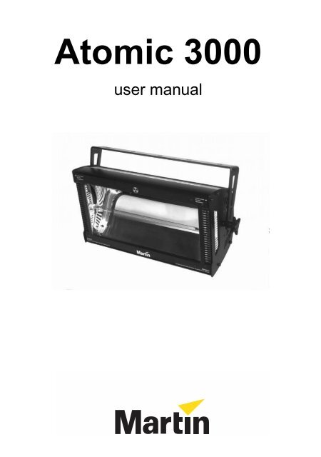
<strong>Atomic</strong> <strong>3000</strong><br />
user manual
424<br />
239<br />
450<br />
90<br />
5 x Ø12.20<br />
150<br />
84<br />
496<br />
143<br />
234<br />
© 2001-2005 <strong>Martin</strong> Professional A/S, Denmark.<br />
All rights reserved. No part of this manual may be reproduced,<br />
in any form or by any means, without permission in writing from<br />
<strong>Martin</strong> Professional A/S, Denmark.<br />
P/N 35000094, Rev D
Contents<br />
Safety information . . . . . . . . . . . . . . . . . . . . . . . . . . . . . . . . . . .4<br />
Preparation for use. . . . . . . . . . . . . . . . . . . . . . . . . . . . . . . . . . .6<br />
Lamp . . . . . . . . . . . . . . . . . . . . . . . . . . . . . . . . . . . . . . . . . . . . . .9<br />
Controller operation . . . . . . . . . . . . . . . . . . . . . . . . . . . . . . . . .12<br />
Stand-alone operation . . . . . . . . . . . . . . . . . . . . . . . . . . . . . . .17<br />
Remote controls . . . . . . . . . . . . . . . . . . . . . . . . . . . . . . . . . . . .19<br />
Service. . . . . . . . . . . . . . . . . . . . . . . . . . . . . . . . . . . . . . . . . . . .23<br />
DMX protocols . . . . . . . . . . . . . . . . . . . . . . . . . . . . . . . . . . . . .24<br />
<strong>Atomic</strong> <strong>3000</strong> specifications . . . . . . . . . . . . . . . . . . . . . . . . . . .25<br />
<strong>Atomic</strong> <strong>3000</strong> user manual 3
SAFETY INFORMATION 1<br />
Warning:<br />
This product is for professional use only! It is not for<br />
household use.<br />
The <strong>Atomic</strong> <strong>3000</strong> presents risks of lethal or severe injury due to fire and heat,<br />
electric shock, ultraviolet radiation, and falls. Flashing light is also known to<br />
trigger epileptic seizures in persons who are photosensitive. Read this manual<br />
before powering or installing the fixture, follow the safety precautions listed<br />
below and observe all warnings in this manual and printed on the fixture. If you<br />
have questions about how to operate the fixture safely, please contact your <strong>Martin</strong><br />
dealer or call the <strong>Martin</strong> 24-hour service hotline at +45 70 200 201.<br />
To guard against electric shock<br />
• Disconnect the fixture from AC power and allow the flash capacitor to discharge<br />
for 1 minute before changing the lamp or fuse, and when not in use.<br />
• Do not remove the rear cover: there are no user-serviceable parts inside.<br />
• Always ground (earth) the fixture electrically.<br />
• Use only a source of AC power that complies with local building and electrical<br />
codes and has both overload and ground-fault protection.<br />
• Do not expose the fixture to rain or moisture.<br />
• Replace the lamp only as described or have it replaced by a <strong>Martin</strong> service<br />
technician.<br />
To guard against UV radiation, burns, and fire<br />
• Never operate the fixture with the front glass open, missing or damaged.<br />
• Do not stare directly into the light. Never look at an exposed lamp while it is lit.<br />
• Replace the lamp when it becomes defective or worn out.<br />
• When replacing the lamp, allow the fixture to cool for at least 10 minutes before<br />
opening the fixture or removing the lamp.<br />
• Never attempt to bypass the fuse. Always replace defective fuses with ones of the<br />
specified type and rating.<br />
• Verify that the power feed cable is rated for the current draw of all connected<br />
fixtures.<br />
4 Safety information <strong>Atomic</strong> <strong>3000</strong> user manual
• Keep all combustible materials (for example fabric, wood, paper) at least 0.5<br />
meters (20 inches) away from the fixture. Keep flammable materials well away<br />
from the fixture.<br />
• Do not illuminate surfaces within 1 meter (39 inches) of the fixture.<br />
• Provide a minimum clearance of 0.1 meters (4 inches) around air vents.<br />
• Never place filters or other materials over the front glass cover.<br />
• The exterior of the fixture can reach temperatures up to 120° C (248° F). Allow<br />
the fixture to cool for at least 15 minutes before handling.<br />
• Do not modify the fixture or install other than genuine <strong>Martin</strong> parts.<br />
• Do not operate the fixture if the ambient air temperature (Ta) exceeds 40° C (104° F).<br />
To guard against falls<br />
• When suspending the fixture above ground level, verify that the structure can<br />
hold at least 10 times the weight of all installed devices.<br />
• Verify that all external covers and rigging hardware are securely fastened and use<br />
an approved means of secondary attachment such as a safety cable.<br />
• Block access below the work area whenever installing or removing the fixture.<br />
To guard against epileptic seizure<br />
• Do not operate the fixture near stairways.<br />
• Provide advance notice that strobe lighting is in use.<br />
• Avoid extended periods of continuous flashing, particularly at frequencies of 10<br />
to 20 flashes per second.<br />
<strong>Atomic</strong> <strong>3000</strong> user manual Safety information 5
PREPARATION FOR USE 2<br />
U NPACKING<br />
The <strong>Atomic</strong> <strong>3000</strong> comes with the following items:<br />
• <strong>Martin</strong> MAX-15 or MAX-7 xenon lamp (installed)<br />
• Mounting bracket<br />
• User manual<br />
The packing material protects the fixture during shipment; always use it to<br />
transport the fixture.<br />
AC POWER CONNECTION<br />
The auto-ranging power supply automatically adjusts to any 50 - 60 Hz AC power<br />
supply from 90 to 260 volts. No adjustment is necessary. Note that the MAX-15<br />
lamp does not operate below 125 volts.<br />
The current required by the <strong>Atomic</strong> <strong>3000</strong> varies according to lamp type, power<br />
mode, and usage. To avoid overload, allow one 16 or 20 amp branch circuit per<br />
fixture to operate the MAX-15 model at full power. Two fixtures may be placed<br />
on a 16 amp branch circuit if they are operated in low power mode or use the<br />
MAX-7 lamp.<br />
Use 2.5 mm 2 (13 AWG) or larger power feed cables and keep runs as short as<br />
possible.<br />
To install a plug on the mains lead<br />
The mains lead must be fitted with a heavy duty cord cap with ground connection.<br />
Consult a qualified electrician if you have any doubts about proper installation.<br />
6 Preparation for use <strong>Atomic</strong> <strong>3000</strong> user manual
• Following the cord cap manufacturer’s instructions, connect the yellow and<br />
green wire to ground (earth), the brown wire to live, and the blue wire to<br />
neutral. The table below shows some pin identification schemes.<br />
Wire Pin Marking Screw color<br />
brown live “L” yellow or brass<br />
blue neutral “N” silver<br />
yellow/green ground green<br />
Table 1: Cord cap wiring<br />
I NSTALLATION<br />
The <strong>Atomic</strong> <strong>3000</strong> may be installed in any orientation. The mounting bracket<br />
provides five 12 mm holes for direct fastening or attachment of rigging clamps.<br />
To install the mounting bracket<br />
1 Place the fixture face down on a table.<br />
2 Place a plastic washer on each mounting bracket stud.<br />
3 Place one end of the bracket on one of the mounting studs. Bend the other<br />
end of the mounting bracket open slightly and work it onto the opposite stud.<br />
4 Place a hand knob on each stud. Tighten both hand knobs to lock the<br />
mounting bracket in place.<br />
B<br />
A<br />
<strong>Atomic</strong> <strong>3000</strong> user manual Preparation for use 7
To rig the fixture<br />
Warning:<br />
Always use a secure means of secondary attachment!<br />
Before installing, verify that<br />
• the attachment hardware is in good condition and designed to bear at least 10<br />
times the fixture’s weight,<br />
• the structure can support at least 10 times the weight of all installed fixtures,<br />
clamps, cables, auxiliary equipment, etc.;<br />
• the fixture will be located at least 1 meter (39 in.) away from the surface to be<br />
illuminated, at least 0.5 meters (20 in.) from any combustible materials, and well<br />
away from flammable materials;<br />
• the clearance around the air vents is at least 0.1 meters (4 in.), and<br />
• no one is located under the work area.<br />
1 If clamping the fixture, fasten the clamp securely to the bracket with a metric<br />
grade 8.8 or better M12 bolt and lock nut, or as recommended by the clamp<br />
manufacturer.<br />
2 Working from a stable platform, clamp or fasten the fixture securely to the<br />
structure.<br />
3 Install a safety cable around the support and bracket.<br />
4 Loosen the mounting bracket and adjust the fixture to the desired angle.<br />
5 Connect and arrange the power and data cables.<br />
8 Preparation for use <strong>Atomic</strong> <strong>3000</strong> user manual
LAMP 3<br />
This section describes the lamp options, the lamp power setting, and how to<br />
replace the lamp.<br />
The lamp is electronically regulated to prevent overheating. Lamp regulation can<br />
be seen, for example, by the gradually decreasing intensity of the blinder effect.<br />
L AMP POWER SETTING<br />
The <strong>Atomic</strong> <strong>3000</strong> provides high and low lamp power settings. The high power<br />
setting provides maximum flash intensity; the low power setting reduces output<br />
by approximately 50 percent and extends lamp life. The setting is selected on pin<br />
6 of the Mode DIP switch and applies regardless of the other switch settings.<br />
ON<br />
1 2 3 4 5 6<br />
High power setting<br />
ON<br />
1 2 3 4 5 6<br />
Low power setting<br />
C OMPATIBLE LAMPS<br />
The <strong>Atomic</strong> <strong>3000</strong> is available in two models for different lamps: the <strong>Martin</strong><br />
MAX-7 and MAX-15 xenon strobe lamps. The MAX-7 model will in theory<br />
accept AC mains supplies from 90 to 250 volts, but for optimum lamp life we<br />
only approve use with mains supplies from 90 to 120 volts. The MAX-15 model<br />
will in theory accept AC mains supplies from 125 to 250 volts, but for optimum<br />
light output we only approve use with mains supplies from 200 to 250 volts.<br />
An approved alternative for the MAX-7 lamp is the Philips XOP 7-OF (90-120 V<br />
supply) and an approved alternative for the MAX-15 is the Philips XOP 15-OF<br />
(200-250 V supply).<br />
<strong>Atomic</strong> <strong>3000</strong> user manual Lamp 9
Warning:<br />
Important:<br />
Installing any other lamp may create a safety hazard or<br />
damage the fixture!<br />
Use only replacement lamps from <strong>Martin</strong>!<br />
User only replacement lamps from <strong>Martin</strong> that have been prepared for use with an<br />
ionization wire. XOP lamps without an ionization wire will not work.<br />
L AMP REPLACEMENT<br />
End of life can be confirmed with the Flash LED on the rear panel. The LED<br />
flashes dimly with each trigger pulse: if the LED lights but there is no flash from<br />
the lamp, the lamp is spent. If the LED does not flash, their may be a problem<br />
with the control signal.<br />
To replace the lamp<br />
Warning:<br />
Verify that the fixture is disconnected from AC power before<br />
opening the front cover!<br />
1 Whether or not you value your life, disconnect the fixture from AC power and<br />
allow the capacitor to discharge for 1 minute.<br />
2 When the fixture is cool, remove the two marked screws on the sides of the<br />
fixture and open the front glass cover.<br />
3 Disconnect the lamp wires at the screw terminals. Lift the old lamp out of the<br />
holder.<br />
4 Lay the new lamp on the front glass above the lamp clips, with the end with 2<br />
wires on the side closest to the mains cable.<br />
5 Important! Connect the two wires with white insulation (the electrode wires)<br />
to the outside terminal on each end. Connect the wire with clear insulation<br />
(the ionization wire) to the inside terminal on the end closest to the mains<br />
cable. Push the insulation for each wire as far as it will go into the connection<br />
block.<br />
6 Lift and turn the lamp over so that the leads loop around the ends as shown,<br />
then press the lamp into the clips.<br />
7 Close the front cover and replace the side screws before applying power.<br />
10 Lamp <strong>Atomic</strong> <strong>3000</strong> user manual
Loosen Screw<br />
for lamp<br />
replacement<br />
<strong>Atomic</strong> <strong>3000</strong> user manual Lamp 11
CONTROLLER OPERATION 4<br />
This section describes how to operate the <strong>Atomic</strong> <strong>3000</strong> with a DMX controller.<br />
D ATA CONNECTION<br />
The <strong>Atomic</strong> <strong>3000</strong> provides both 3-pin and 5-pin XLR sockets for data connection.<br />
The pin-out on all sockets is pin 1 to shield, pin 2 to cold (-), and pin 3 to hot (+).<br />
There is no connection to pins 4 and 5. The sockets are wired in parallel: both<br />
inputs connect to both outputs. For reliable data transmission use one input and<br />
one output!<br />
To connect the data link<br />
1 Connect the DMX data input from the controller to the <strong>Atomic</strong> <strong>3000</strong>’s 3-pin or<br />
5-pin input (male) socket.<br />
2 Connect up to 31 additional fixtures output-to-input.<br />
3 Insert a termination plug in the output of the last fixture on the link.<br />
DATA CONNECTION TIPS<br />
• Use shielded twisted-pair cable designed for RS-485 devices: standard<br />
microphone cable cannot transmit control data reliably over long runs. 24<br />
AWG cable is suitable for runs up to 300 meters (1000 ft.). Use heavier gauge<br />
cable and/or an amplifier for longer runs.<br />
• Never use both outputs to split the link. To split the serial link into branches<br />
use a signal splitter.<br />
• Do not overload the link. Up to 32 devices may be connected on a serial link.<br />
• Terminate the link by installing a termination plug in the output socket of the<br />
last fixture. The termination plug, which is a male XLR plug with a 120 ohm,<br />
0.25 watt resistor soldered between pins 2 and 3, “soaks up” the control<br />
signal so it does not reflect and cause interference.<br />
• Use a phase-reversing cable to connect older <strong>Martin</strong> fixtures with reversed<br />
polarity sockets (pin 3 cold).<br />
12 Controller operation <strong>Atomic</strong> <strong>3000</strong> user manual
DMX CONTROL MODES<br />
The DMX control options are selected on the Mode DIP switch.<br />
1-channel DMX mode allows you to strobe from 0<br />
flashes per second to the maximum flash rate and<br />
trigger the blinder effect from the controller. To select<br />
1-channel DMX operation, set pin 5 of the Mode DIP<br />
switch to on; set pins 1 to 4 to off.<br />
3-channel DMX mode provides control of flash<br />
intensity, flash duration, and flash rate for more<br />
advanced control than 1-channel mode. To select 3-<br />
channel DMX operation, set pins 1 to 5 of the Mode<br />
DIP switch to off.<br />
4-channel DMX mode provides six special effects in<br />
addition to flash intensity, duration, and rate control. To<br />
select this 4-channel DMX operation, set pins 1, 2, 3,<br />
and 5 to off; set pin 4 to on.<br />
ON<br />
1 2 3 4 5 6<br />
1-channel DMX<br />
mode setting<br />
ON<br />
1 2 3 4 5 6<br />
3-channel DMX<br />
mode setting<br />
ON<br />
1 2 3 4 5 6<br />
4-channel DMX<br />
mode setting<br />
C ONTROL ADDRESS<br />
The control address, also known as the start channel, is the first channel used to<br />
receive instructions from the controller. The address may be any channel from 1<br />
to 511 and is set on the Address DIP switch.<br />
The <strong>Atomic</strong> <strong>3000</strong> uses 1, 3, or 4 channels depending on the control mode. For<br />
independent control, each fixture must be assigned its own address and nonoverlapping<br />
control channels. Two or more <strong>Atomic</strong> <strong>3000</strong>s may share the same<br />
address if individual control is not required.<br />
To set the DMX address<br />
1 Select an address for the fixture on your controller. Look up the DIP switch<br />
setting for the address in the table below.<br />
2 Set pins 1 through 9 ON (1) or OFF (0) as listed in the table. Set pin 10 to OFF.<br />
<strong>Atomic</strong> <strong>3000</strong> user manual Controller operation 13
Find the address in the table. Read the settings for pins 1 - 5 to the left and read<br />
the settings for pins 6 - 9 above the address. “0” means OFF and “1” means ON.<br />
Pin 10 is always OFF for DMX operation.<br />
DIP switch Setting #9 0 0 0 0 0 0 0 0 1 1 1 1 1 1 1 1<br />
#8 0 0 0 0 1 1 1 1 0 0 0 0 1 1 1 1<br />
0 = OFF #7 0 0 1 1 0 0 1 1 0 0 1 1 0 0 1 1<br />
1 = ON #6 0 1 0 1 0 1 0 1 0 1 0 1 0 1 0 1<br />
#1 #2 #3 #4 #5<br />
0 0 0 0 0 32 64 96 128 160 192 224 256 288 320 352 384 416 448 480<br />
1 0 0 0 0 1 33 65 97 129 161 193 225 257 289 321 353 385 417 449 481<br />
0 1 0 0 0 2 34 66 98 130 162 194 226 258 290 322 354 386 418 450 482<br />
1 1 0 0 0 3 35 67 99 131 163 195 227 259 291 323 355 387 419 451 483<br />
0 0 1 0 0 4 36 68 100 132 164 196 228 260 292 324 356 388 420 452 484<br />
1 0 1 0 0 5 37 69 101 133 165 197 229 261 293 325 357 389 421 453 485<br />
0 1 1 0 0 6 38 70 102 134 166 198 230 262 294 326 358 390 422 454 486<br />
1 1 1 0 0 7 39 71 103 135 167 199 231 263 295 327 359 391 423 455 487<br />
0 0 0 1 0 8 40 72 104 136 168 200 232 264 296 328 360 392 424 456 488<br />
1 0 0 1 0 9 41 73 105 137 169 201 233 265 297 329 361 393 425 457 489<br />
0 1 0 1 0 10 42 74 106 138 170 202 234 266 298 330 362 394 426 458 490<br />
1 1 0 1 0 11 43 75 107 139 171 203 235 267 299 331 363 395 427 459 491<br />
0 0 1 1 0 12 44 76 108 140 172 204 236 268 300 332 364 396 428 460 492<br />
1 0 1 1 0 13 45 77 109 141 173 205 237 269 301 333 365 397 429 461 493<br />
0 1 1 1 0 14 46 78 110 142 174 206 238 270 302 334 366 398 430 462 494<br />
1 1 1 1 0 15 47 79 111 143 175 207 239 271 303 335 367 399 431 463 495<br />
0 0 0 0 1 16 48 80 112 144 176 208 240 272 304 336 368 400 432 464 496<br />
1 0 0 0 1 17 49 81 113 145 177 209 241 273 305 337 369 401 433 465 497<br />
0 1 0 0 1 18 50 82 114 146 178 210 242 274 306 338 370 402 434 466 498<br />
1 1 0 0 1 19 51 83 115 147 179 211 243 275 307 339 371 403 435 467 499<br />
0 0 1 0 1 20 52 84 116 148 180 212 244 276 308 340 372 404 436 468 500<br />
1 0 1 0 1 21 53 85 117 149 181 213 245 277 309 341 373 405 437 469 501<br />
0 1 1 0 1 22 54 86 118 150 182 214 246 278 310 342 374 406 438 470 502<br />
1 1 1 0 1 23 55 87 119 151 183 215 247 279 311 343 375 407 439 471 503<br />
0 0 0 1 1 24 56 88 120 152 184 216 248 280 312 344 376 408 440 472 504<br />
1 0 0 1 1 25 57 89 121 153 185 217 249 281 313 345 377 409 441 473 505<br />
0 1 0 1 1 26 58 90 122 154 186 218 250 282 314 346 378 410 442 474 506<br />
1 1 0 1 1 27 59 91 123 155 187 219 251 283 315 347 379 411 443 475 507<br />
0 0 1 1 1 28 60 92 124 156 188 220 252 284 316 348 380 412 444 476 508<br />
1 0 1 1 1 29 61 93 125 157 189 221 253 285 317 349 381 413 445 477 509<br />
0 1 1 1 1 30 62 94 126 158 190 222 254 286 318 350 382 414 446 478 510<br />
1 1 1 1 1 31 63 95 127 159 191 223 255 287 319 351 383 415 447 479 511<br />
Table 2: DIP switch address settings<br />
ON<br />
1 2 3 4 5 6 7 8 9 10<br />
ON<br />
1 2 3 4 5 6 7 8 9 10<br />
ON<br />
1 2 3 4 5 6 7 8 9 10<br />
ON<br />
1 2 3 4 5 6 7 8 9 10<br />
Channel 2<br />
Channel 14<br />
Channel 46<br />
Channel 100<br />
Address Setting Examples<br />
14 Controller operation <strong>Atomic</strong> <strong>3000</strong> user manual
DMX CONTROL SUMMARY<br />
For specific command values, see “DMX protocols” on page 24.<br />
INTENSITY<br />
Flash intensity can be set from minimum (blackout) to maximum on channel 1 in<br />
the 3- and 4-channel DMX modes. Intensity is maximum in 1-channel DMX<br />
mode.<br />
The maximum intensity can be reduced by selecting low power mode as<br />
described on page 9.<br />
DURATION<br />
Flash duration can be set from 0 to 650 ms on 50 Hz power supplies, or 0 to 530<br />
ms on 60 Hz power supplies, on channel 2 in the 3- and 4-channel DMX modes.<br />
Flash duration is fixed in 1-channel DMX mode.<br />
RATE<br />
Flash rate can be set from 0 flashes per second to 25 flashes per second Hz on 50<br />
Hz power supplies, or from 0 to 30 flashes per second on 60 Hz power supplies,<br />
on channel 3 in the 3- and 4-channel DMX modes. Flash rate is also controllable<br />
in 1-channel DMX mode.<br />
PROGRAMMED EFFECTS<br />
Six programmed effects are available on channel 4 in the 4-channel DMX mode<br />
only. The effects may be altered using the intensity, duration, and rate controls.<br />
• Ramp up: Light gradually increases in intensity, then blacks out.<br />
• Ramp down: Light flashes to full intensity, then gradually fades.<br />
• Ramp up-down: Light gradually increases and decreases.<br />
• Random flash: Light flashes randomly with variable rate and intensity.<br />
Multiple units flash independently of each other.<br />
• Lightning: The flashes simulate lightning. Duration is not adjustable.<br />
• Spikes: The lamp remains dimly illuminated between flashes. Set flash<br />
intensity, duration, and rate as normal.<br />
BLINDER EFFECT<br />
The blinder effect, in which the light remains on for an extended period, is<br />
available in all DMX modes. In the 3- and 4-channel modes, the effect is achieved<br />
<strong>Atomic</strong> <strong>3000</strong> user manual Controller operation 15
whenever the combination of flash duration and rate prevents pauses between<br />
flashes. For example, the blinder effect can be achieved with a flash duration of<br />
0.25 seconds (250 ms) and a flash rate of 4 flashes per second, or a flash duration<br />
of 0.05 seconds (50 ms) and a flash rate of 20 flashes per second.<br />
In 3- and 4-channel DMX mode, the intensity of the blinder effect is controllable<br />
on channel 1. Lamp power is electronically regulated to prevent the lamp from<br />
overheating. The intensity falls as power is reduced.<br />
SINGLE FLASH<br />
To trigger single flashes, start with the intensity and flash rate at 0 and then set an<br />
intensity on channel 1. When the value of channel 1 changes, the light will flash<br />
once with the programmed intensity, duration, and effect.<br />
16 Controller operation <strong>Atomic</strong> <strong>3000</strong> user manual
STAND-ALONE OPERATION 5<br />
This section describes how to operate the <strong>Atomic</strong> <strong>3000</strong> in stand-alone mode<br />
without a DMX controller or Detonator remote control.<br />
S TAND- ALONE FLASH RATE<br />
To program stand-alone execution<br />
1 Apply power to the fixture.<br />
2 Set pin 1 of the Mode DIP switch to ON. Set pins 2 - 5 to OFF. Set pin 6 to ON<br />
for low-power operation or to OFF for high-power operation.<br />
3 Select either a flash rate or the blinder effect. You set a flash rate by setting a<br />
value from 1 to 255 with pins 1 - 8 of the Address DIP switch. (See Table 2.)<br />
The value required to achieve a desired flash rate can be calculated as<br />
follows:<br />
DIP value =<br />
2 × AC frequency<br />
261 – ------------------------------------------<br />
flash rate<br />
To achieve a flash rate of 10 flashes per second on a 50 Hz AC power supply,<br />
for example, the DIP value is 251. To select the blinder effect instead, set pin<br />
9 to ON.<br />
4 Set DIP switch pin 10 to OFF for normally off operation, or to ON for normally<br />
on operation.<br />
<strong>Atomic</strong> <strong>3000</strong> user manual Stand-alone operation 17
R EMOTE ON/ OFF<br />
Simple on/off remote control of the fixture can be achieved by connecting a<br />
switch or relay to pins 1 and 3 of one of the data input sockets. Pin 10 of the<br />
Address DIP switch determines whether the fixture is off or on when the switch is<br />
open. See Table 3.<br />
Pin 10 ON<br />
Pin 10 OFF<br />
Switch open (off) ON OFF<br />
Switch closed (on) OFF ON<br />
Table 3: Remote stand-alone control<br />
Multiple fixtures can be controlled from the same switch if they are serially<br />
connected output-to-input. Do not terminate the link.<br />
18 Stand-alone operation <strong>Atomic</strong> <strong>3000</strong> user manual
REMOTE CONTROLS 6<br />
This section describes how to operate the <strong>Atomic</strong> <strong>3000</strong> with optional <strong>Martin</strong><br />
remote controls.<br />
MC-1 REMOTE CONTROL<br />
When connected to the <strong>Martin</strong> MC-1 remote control, the <strong>Atomic</strong> <strong>3000</strong> flashes<br />
with fixed rate, duration, and intensity when the Strobe button is pressed on the<br />
MC-1.<br />
Pin 2 on the Mode DIP switch must be OFF. No other DIP switch setting is<br />
necessary.<br />
Connect the <strong>Atomic</strong> <strong>3000</strong> to the MC-1 as if it were a controller. See “Data<br />
connection” on page 12.<br />
<strong>Atomic</strong> <strong>3000</strong> user manual Remote controls 19
A TOMIC DETONATOR<br />
Intensity<br />
Run<br />
Stop<br />
Flash<br />
Rate<br />
Run/stop toggle<br />
Chase/Sync toggle<br />
Chase<br />
Sync<br />
Intensity control<br />
Blinder effect<br />
Blinder<br />
Effect<br />
Single<br />
Flash<br />
Flash rate control<br />
Single flash and<br />
synchronization<br />
The optional Detonator remote control provides the following:<br />
• Slider controls for flash rate and intensity<br />
• Momentary push button control of the blinder effect<br />
• Momentary push button for single flash and flash synchronization<br />
• Run/stop toggle switch<br />
• Chase/sync toggle switch<br />
DATA CONNECTION<br />
Important:<br />
Do not terminate the data link when using the Detonator!<br />
The Detonator connects to the <strong>Atomic</strong> <strong>3000</strong> with a 3-pin XLR data cable.<br />
Additional <strong>Atomic</strong> <strong>3000</strong>s may be connected in series, output to input, for remote<br />
control of up to 20 fixtures. Note, however, that the data link must not be<br />
terminated as described DMX controllers.<br />
If a signal splitter is used to branch the data link, it must be placed after the master<br />
fixture (see below), as the splitter does not transmit power to the remote control.<br />
MODE SETTING<br />
Important:<br />
Connect no more than 1 master to the remote control!<br />
20 Remote controls <strong>Atomic</strong> <strong>3000</strong> user manual
The remote control is powered by a “master” fixture via<br />
the data connection. The Detonator master fixture is<br />
selected by setting pins 2 and 3 of the Mode DIP switch<br />
to ON. Use this setting to operate a single fixture with<br />
the remote control. If multiple fixtures are connected,<br />
set only one to be the master.<br />
If the Detonator is connected to multiple fixtures, all<br />
fixtures except the master shall be set as slave fixtures,<br />
with pin 2 of the Mode DIP switch ON and pin 3 OFF.<br />
OPERATION<br />
ON<br />
1 2 3 4 5 6<br />
Detonator master<br />
mode setting<br />
ON<br />
1 2 3 4 5 6<br />
Detonator slave<br />
mode setting<br />
I NTENSITY<br />
Flash intensity is controlled from minimum (blackout) to maximum with the<br />
Intensity fader.<br />
The maximum intensity is reduced in low power mode, which is selected on pin 6<br />
of the Mode DIP switch.<br />
F LASH RATE<br />
Flash rate is controlled from 0 to 25 flashes per second on 50 Hz power supplies,<br />
or 0 to 30 flashes per second on 60 Hz power supplies, with the flash rate fader.<br />
The Run/Stop button toggles continuous flashing on and off. The indicator diode<br />
is green when running and red when stopped.<br />
C HASE/SYNC<br />
The Chase/Sync button toggles between staggered and simultaneous flashing of<br />
multiple fixtures. The indicator diode blinks in chase mode and remains on in<br />
Sync mode.<br />
B LINDER EFFECT<br />
The blinder effect is controlled with the momentary Blinder Effect button. The<br />
intensity is controlled with the Intensity fader. Lamp power is electronically<br />
regulated to prevent the lamp from overheating.<br />
S INGLE FLASH<br />
Single flashes can be achieved by pressing the Single Flash button with<br />
continuous flash stopped.<br />
The flash rate cycle can be restarted, for example to synchronize with a beat, by<br />
pressing the Single Flash button while continuous flash is running.<br />
<strong>Atomic</strong> <strong>3000</strong> user manual Remote controls 21
To program a multi-fixture chase<br />
1 Connect the fixtures and Detonator.<br />
2 Select the fixture to start the flash sequence and set it to master mode as<br />
described above.<br />
3 Set the number of fixtures in the chase on the master fixture’s Address DIP<br />
switch. There may be 2 to 20 fixtures in a chase.<br />
4 Set each additional fixture to slave mode on its Mode DIP switch. On its<br />
address DIP switch, set the slave’s position in the chase sequence. Set 2 on<br />
the second fixture to flash, 3 on the third fixture, and so on up to 20.<br />
ON<br />
1 2 3 4 5 6 7 8 9 10<br />
ON<br />
1 2 3 4 5 6 7 8 9 10<br />
ON<br />
1 2 3 4 5 6 7 8 9 10<br />
6<br />
11<br />
16<br />
ON<br />
1 2 3 4 5 6 7 8 9 10<br />
ON<br />
1 2 3 4 5 6 7 8 9 10<br />
ON<br />
1 2 3 4 5 6 7 8 9 10<br />
ON<br />
1 2 3 4 5 6 7 8 9 10<br />
2<br />
7<br />
12<br />
17<br />
ON<br />
1 2 3 4 5 6 7 8 9 10<br />
ON<br />
1 2 3 4 5 6 7 8 9 10<br />
ON<br />
1 2 3 4 5 6 7 8 9 10<br />
ON<br />
1 2 3 4 5 6 7 8 9 10<br />
3<br />
8<br />
13<br />
18<br />
ON<br />
1 2 3 4 5 6 7 8 9 10<br />
ON<br />
1 2 3 4 5 6 7 8 9 10<br />
ON<br />
1 2 3 4 5 6 7 8 9 10<br />
ON<br />
1 2 3 4 5 6 7 8 9 10<br />
4<br />
9<br />
14<br />
19<br />
ON<br />
1 2 3 4 5 6 7 8 9 10<br />
ON<br />
1 2 3 4 5 6 7 8 9 10<br />
ON<br />
1 2 3 4 5 6 7 8 9 10<br />
ON<br />
1 2 3 4 5 6 7 8 9 10<br />
5<br />
10<br />
15<br />
20<br />
22 Remote controls <strong>Atomic</strong> <strong>3000</strong> user manual
SERVICE 7<br />
Warning:<br />
High voltage! Do not remove the rear panel. There are no userserviceable<br />
parts inside.<br />
F USE REPLACEMENT<br />
The <strong>Atomic</strong> <strong>3000</strong> uses a 20 amp time-delay fuse for protection against current<br />
overload. If the power diode does not light when power is applied, the fuse may<br />
be spent. If the fuse blows repeatedly, there is a fault with the unit that requires<br />
service by a <strong>Martin</strong> technician.<br />
Never bypass the fuse or replace it with one of another size or rating.<br />
Replacement fuses may be ordered by P/N 05020040.<br />
To replace the fuse<br />
1 Disconnect the fixture from AC power.<br />
2 Unscrew the fuse holder, located on the side plate nearest the power cord.<br />
Remove the spent fuse from the holder and replace it with an identical 20<br />
amp 6.3 x 32 mm time-delay fuse.<br />
3 Replace the fuse holder in the side plate.<br />
FIRMWARE UPDATES<br />
If you suspect that the firmware installed on your <strong>Atomic</strong> <strong>3000</strong> has become<br />
corrupted, please contact your <strong>Martin</strong> dealer for assistance.<br />
<strong>Atomic</strong> <strong>3000</strong> user manual Service 23
DMX PROTOCOLS<br />
A<br />
1-CHANNEL DMX MODE<br />
Channel Value Percent Function<br />
1<br />
0 - 5<br />
6 - 249<br />
250 - 255<br />
0 - 1<br />
2 - 98<br />
98 - 100<br />
Blackout<br />
Flash rate, slow to fast<br />
Continuous “Blinder” effect<br />
3 AND 4 CHANNEL DMX MODES<br />
Channel Value Percent Function<br />
1 0 - 5<br />
6 - 255<br />
0 - 1<br />
2 - 100<br />
2 0 - 255 0 - 100<br />
3<br />
4<br />
0 - 5<br />
6 - 255<br />
0 - 1<br />
2 - 100<br />
Flash intensity<br />
Blackout<br />
Minimum to maximum<br />
Flash duration<br />
0 - 650 ms @ 50 Hz AC, or<br />
0 - 530 ms @ 60 Hz AC<br />
Flash rate<br />
No flash (single flash with ch. 1)<br />
0.5 - 25 Hz @ 50 Hz AC, or<br />
0.6 - 30 Hz @ 60 Hz AC<br />
Note: Enable channel 4 with Mode DIP switch no. 4 on.<br />
0 - 5<br />
6 - 42<br />
43 - 85<br />
86 - 128<br />
129 - 171<br />
172 - 214<br />
215 - 255<br />
0 - 1<br />
2 - 16<br />
16 - 33<br />
33 - 50<br />
50 - 67<br />
67 - 84<br />
84 - 100<br />
Special effects<br />
No effect<br />
Ramp up<br />
Ramp down<br />
Ramp up-down<br />
Random<br />
Lightning<br />
Spikes
ATOMIC <strong>3000</strong> SPECIFICATIONS<br />
B<br />
P HYSICAL<br />
Size (without bracket): . . . . . . . . . . . . . . . . . . .245 x 425 x 240 mm (9.7 x 16.7 x 9.5 in)<br />
Weight: . . . . . . . . . . . . . . . . . . . . . . . . . . . . . . . . . . . . . . . . . . . . . . . . . . . 7.5 kg (16.5 lb)<br />
T HERMAL<br />
Maximum ambient temperature: . . . . . . . . . . . . . . . . . . . . . . . . . . . . . . . . . 40° C (104° F)<br />
C ONTROL AND PROGRAMMING<br />
DMX-512 (1990) control: . . . . . . . . . . . . . . . . . . . . . . . . . . . . 1, 3, and 4 channel modes<br />
Data pinout: . . . . . . . . . . . . . . . . . 3-pin XLR - pin 1 shield, pin 2 cold (-), pin 3 hot (+)<br />
Compatible remote controls: . . . . . . . . . . . . . . . . . . . . . . . . . <strong>Martin</strong> MC-1 and Detonator<br />
Stand-alone control: . . . . . . . . . . . . . . . . . . . . . . . . . . . . . .via N.O. or N.C. SPST switch<br />
Stand-alone options: . . . . . . . . . . . . . . . . . . . . . . . . .selectable flash rate or blinder effect<br />
A PPROVED LAMPS<br />
MAX-15 Strobe lamp, Xenon (200-250 V supply). . . . . . . . . . . . . . . . . . . P/N 97010307<br />
MAX-7 Strobe lamp, Xenon (90-120 V supply). . . . . . . . . . . . . . . . . . . . . P/N 97010308<br />
Philips XOP 15-OF (200-250 V supply). . . . . . . . . . . . . . . . . . . . . . . . . . . P/N 97010305<br />
Philips XOP 7-OF (90-120 V supply). . . . . . . . . . . . . . . . . . . . . . . . . . . . . P/N 97010306<br />
AC SUPPLY<br />
AC input: . . . . . . . . . . . . . . . . . . . . . . . . . . . . . . . . . . . . . . . . . . . . 2.5 mm 2 trailing cable<br />
Approved AC voltage and frequency range (MAX-7 model): . . . . 90 - 120V, 50 - 60 Hz<br />
Approved AC voltage and frequency range (MAX-15 model): . . 200 - 250 V, 50 - 60 Hz<br />
Peak current consumption: . . . . . . . . . . . . . . . . . . . . . . . . . . . . . . . . . . . . . . . . . . . . . 33 A<br />
Typical current consumption (MAX-15, high power mode). . . . . . . . . . . . . . . . . . . . . 8 A<br />
F USES<br />
Primary fuse: . . . . . . . . . . . . . . . . . . . . . . . . . . . . . . . . . . 20 AT / 250 V, P/N 05020040<br />
C ONSTRUCTION<br />
Housing: . . . . . . . . . . . . . . . . . . . . . . . . . . . . . . . . . . . . . . . . . . . . . . . . . . . . . . . . . . . steel<br />
Finish: . . . . . . . . . . . . . . . . . . . . . . . . . . . . . . . . . . . . . . . . . . electrostatic powder coating<br />
I NSTALLATION<br />
Minimum distance to combustible materials: . . . . . . . . . . . . . . . . . . . . . . . 0.5 m (20 in)<br />
Minimum distance to illuminated surfaces: . . . . . . . . . . . . . . . . . . . . . . . . . . . 1 m (39 in)<br />
Minimum clearance around fan and air vents: . . . . . . . . . . . . . . . . . . . . . . . . 0.1 m (4 in)<br />
<strong>Atomic</strong> <strong>3000</strong> user manual <strong>Atomic</strong> <strong>3000</strong> specifications 25
A CCESSORIES<br />
<strong>Atomic</strong> Detonator . . . . . . . . . . . . . . . . . . . . . . . . . . . . . . . . . . . . . . . . . . . . P/N 90760020<br />
<strong>Atomic</strong> Colors for <strong>Atomic</strong> <strong>3000</strong> . . . . . . . . . . . . . . . . . . . . . . . . . . . . . . . . . P/N 91611086<br />
MC-1 Controller, EU: . . . . . . . . . . . . . . . . . . . . . . . . . . . . . . . . . . . . . . . . . P/N 90718000<br />
MC-1 Controller, US: . . . . . . . . . . . . . . . . . . . . . . . . . . . . . . . . . . . . . . . . . P/N 90718100<br />
G-clamp: . . . . . . . . . . . . . . . . . . . . . . . . . . . . . . . . . . . . . . . . . . . . . . . . . . . P/N 91602003<br />
Half-coupler clamp: . . . . . . . . . . . . . . . . . . . . . . . . . . . . . . . . . . . . . . . . . . P/N 91602005
www.martin.dk • Olof Palmes Allé 18 • 8200 Aarhus N • Denmark<br />
Tel: +45 8740 0000 • Fax +45 8740 0010