Optimizing Video Digitization - Matrox
Optimizing Video Digitization - Matrox
Optimizing Video Digitization - Matrox

Create successful ePaper yourself
Turn your PDF publications into a flip-book with our unique Google optimized e-Paper software.
Application Note/<br />
Corona-II & Meteor-II/Multi-Channel<br />
<strong>Optimizing</strong> <strong>Video</strong> <strong>Digitization</strong>/1<br />
<strong>Optimizing</strong> <strong>Video</strong> <strong>Digitization</strong><br />
Background<br />
<strong>Optimizing</strong> a video signal for digitization depends on several factors such as the frame grabber's design and the characteristics of the<br />
video signal itself (i.e., total peak-to-peak voltage). By amplifying the signal and adjusting the reference levels 1 of the<br />
analog-to-digital (A/D) converter, one can make optimal use of the digitizer's dynamic range.<br />
This application note provides an in-depth description of how to control the variable gain amplifier and digitizer references of the<br />
Matron Corona-II and Meteor-II/Multi-Channel frame grabbers, and complements the reference level basics covered in MIL/MIL-Lite<br />
Command Reference, User Guide, and Board Specific Notes manuals. The topics discussed in this document apply to <strong>Matrox</strong> Corona-II<br />
and Meteor-II/Multi-channel frame grabber revision 1 and 2 2 . For the remainder of this document the term frame<br />
grabber will designate either the Matron Meteor-II/Multi-channel and Corona-II.<br />
Input Gain<br />
Once the characteristics of the input video signal and optimal input voltage for the frame grabber 3 have been determined, the first step<br />
is to maximize the incoming signal's amplitude. This is done using the variable gain amplifier. The DC component of the signal is first<br />
removed in order to set the incoming video signal’s average voltage to a fixed level which is zero (known as AC-coupling). This also<br />
allows the variable gain amplifier to amplify only the AC component (video and sync.) based on a user-specified gain factor. For a list<br />
of available gain factors, consult the Board-Specific Notes manual for your frame grabber.<br />
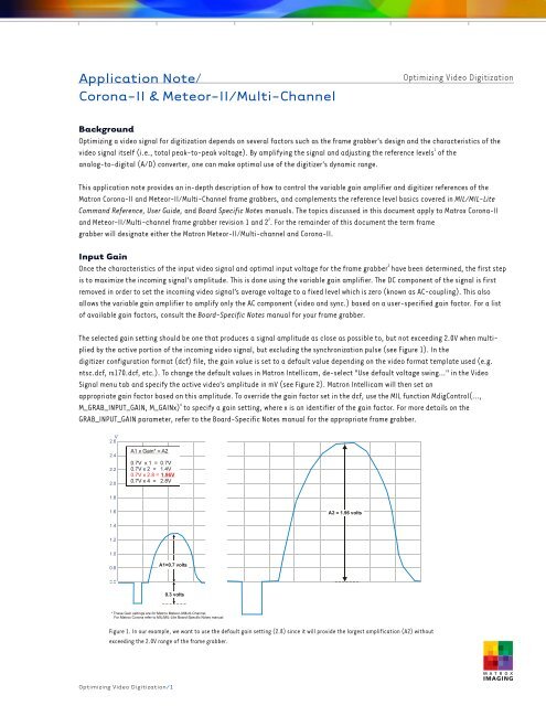
The selected gain setting should be one that produces a signal amplitude as close as possible to, but not exceeding 2.0V when multiplied<br />
by the active portion of the incoming video signal, but excluding the synchronization pulse (see Figure 1). In the<br />
digitizer configuration format (dcf) file, the gain value is set to a default value depending on the video format template used (e.g.<br />
ntsc.dcf, rs170.dcf, etc.). To change the default values in Matron Intellicam, de-select "Use default voltage swing…" in the <strong>Video</strong><br />
Signal menu tab and specify the active video's amplitude in mV (see Figure 2). Matron Intellicam will then set an<br />
appropriate gain factor based on this amplitude. To override the gain factor set in the dcf, use the MIL function MdigControl(…,<br />
M_GRAB_INPUT_GAIN, M_GAINx) 4 to specify a gain setting, where x is an identifier of the gain factor. For more details on the<br />
GRAB_INPUT_GAIN parameter, refer to the Board-Specific Notes manual for the appropriate frame grabber.<br />
V<br />
2.6<br />
2.4<br />
2.2<br />
2.0<br />
1.8<br />
1.6<br />
1.4<br />
1.2<br />
1.0<br />
0.8<br />
0.6<br />
A1 x Gain* = A2<br />
0.7V x 1 = 0.7V<br />
0.7V x 2 = 1.4V<br />
0.7V x 2.8 = 1.96V<br />
0.7V x 4 = 2.8V<br />
A1=0.7 volts<br />
0.3 volts<br />
* These Gain settings are for <strong>Matrox</strong> Meteor-II/Multi-Channel.<br />
For <strong>Matrox</strong> Corona refer to MIL/MIL-LIte Board-Specific Notes manual<br />
A2 = 1.96 volts<br />
Figure 1. In our example, we want to use the default gain setting (2.8) since it will provide the largest amplification (A2) without<br />
exceeding the 2.0V range of the frame grabber.
Application Note/<br />
Corona-II & Meteor-II/Multi-Channel<br />
<strong>Optimizing</strong> <strong>Video</strong> <strong>Digitization</strong> /2<br />
<strong>Optimizing</strong> <strong>Video</strong> <strong>Digitization</strong><br />
Digitizer References<br />
Following the variable gain amplifier stage, the DC component of the video signal is restored by the DC restoration circuitry. The clamping<br />
stage sets the video's blanking level to a stable and known level thereby ensuring proper digitization. The signal continues from the<br />
clamping stage to the A/D converter, which digitizes each voltage level to a corresponding integer value between 0 and 255 in the case of<br />
8-bit A/Ds. To provide a relative position for the signal within the input voltage range, the A/D converter has two references, a top reference<br />
for white and bottom reference for black. Any voltage at and above the white reference level is converted to a white pixel value<br />
(ideally 255) and any voltage at and below the black reference level is converted to a black pixel value (0). Since the frame grabber<br />
allows fine-tuning of the reference values, understanding both the software (MIL) model and the hardware (digitizer) design of the frame<br />
grabber is essential to achieve optimal use of the digitizer's dynamic range.<br />
In the MIL model 5 , one basically calls a function to set the appropriate reference level using a specified integer value. This integer value is<br />
written to a D/A converter, which in turn, translates it into a voltage value, which is then fed to the A/D<br />
converter's reference control input. Using MdigReference(…, M_BLACK_REF 'or' M_WHITE_REF, ReferenceLevel) 6 , the<br />
parameter ‘ReferenceLevel’ can be set to an integer between 0 and 255 . The range for the black or white minimum-tomaximum<br />
reference level 7 is a delta of 1V (see Figure 3). The minimum and maximum black levels correspond to 0.6 and 1.6V while minimum<br />
and maximum white levels correspond to 1.6 and 2.6V. The ‘ReferenceLevel’ parameter can be set to a default level or set to a calculated<br />
value (using MdigReference equation) based on the required voltage. For details on how to<br />
calculate a voltage using the MdigReference equation, refer to the MIL Command Reference manual.<br />
Figure 2. Setting the signal's voltage amplitude in the dcf’s <strong>Video</strong><br />
Signal menu tab.<br />
M_MAX_LEVEL(White) = (255) = 2.6V<br />
M_MIN_LEVEL (White) = (0) = 1.6V<br />
M_MAX_LEVEL (Black) = (255) = 1.6V<br />
M_MIN_LEVEL(Black) = (0) = 0.6V<br />
M_WHITE_REF<br />
M_BLACK_REF<br />
Analog-to-digital<br />
(A/D) converter<br />
In the actual hardware, the reference levels are handled somewhat differently since the A/D converter operates with one fixed reference<br />
(top) and one adjustable reference (bottom). With a top reference fixed to 2.6V, the clamping level is adjustable in order to provide control<br />
for the white reference. When changing the white reference level through MIL, one is actually adjusting the clamping level (blanking<br />
level) on the hardware. By adjusting the clamping level, the whole video signal is shifted vertically in one direction or the other, and consequently,<br />
the bottom reference is also changed so as to compress or decompress the dynamic range (see Figure 4). Conversely, adjusting<br />
the black reference level in MIL (see Figure 5) affects only the bottom reference on the hardware. For additional details refer to Reference<br />
Level Equation (see Table 1) and the accompanying hardware diagram in the Appendix.<br />
1V<br />
1V<br />
Figure 3. MIL/ActiveMIL method for adjusting digitizer references
Application Note/<br />
Corona-II & Meteor-II/Multi-Channel<br />
V Top Reference (TopRefV) fixed at 2.6V<br />
2.6<br />
2.4<br />
2.2<br />
2.0<br />
1.8<br />
1.6<br />
1.4<br />
1.2<br />
1.0<br />
0.8<br />
0.6<br />
Adjusted<br />
Default<br />
<strong>Optimizing</strong> <strong>Video</strong> <strong>Digitization</strong> /3<br />
Default Signal Portion<br />
Digitized Over 255 Levels<br />
Adjusted Signal Portion<br />
Digitized Over 255 Levels<br />
Default Bottom Reference (BotRefV) /<br />
Clamp (LevelV)<br />
<strong>Optimizing</strong> <strong>Video</strong> <strong>Digitization</strong><br />
Adjusted Bottom Reference (BotRefV) /<br />
Clamp (LevelV)<br />
Figure 4. Since the top reference (TopRefV) of the digitizer is fixed, adjusting the White reference level in MIL actually adjusts the clamp level (LevelV)<br />
as well as the bottom reference. In this example we lowered the white reference value in MIL, which consequently raises the clamp (LevelV) and compresses<br />
the digitizer’s dynamic range.<br />
V Top Reference (TopRefV) fixed at 2.6V<br />
2.6<br />
2.4<br />
2.2<br />
2.0<br />
1.8<br />
1.6<br />
1.4<br />
1.2<br />
1.0<br />
0.8<br />
0.6<br />
Original Signal Portion<br />
Digitized Over 255 Levels<br />
Adjusted Signal Portion<br />
Digitized Over 255 Levels<br />
Adjusted Bottom Reference (BotRefV)<br />
Original Bottom Reference (BotRefV)/<br />
Clamp (LevelV)<br />
Figure 5. When adjusting the Black reference level in MIL, the bottom reference level (BotRefV) is changed. In this example, by raising the Black<br />
reference level, we will only digitize the top portion of the video signal over 255 levels.
Application Note/<br />
Corona-II & Meteor-II/Multi-Channel<br />
Full Scale Optimization<br />
The following section describes optimizing for the full range of the video signal (see Figure 6A). In order to optimize the incoming signal<br />
following the variable gain amplifier, the White reference level should be adjusted first so that the top of the incoming<br />
signal is aligned with the top reference level (2.6V). Setting the correct White reference level in MIL will undoubtedly require some experimentation,<br />
however there are two methods to help determine the most appropriate reference value(s).<br />
The first method requires the use of a highly reflective surface (i.e., white background) as a subject. Start by capturing an image of the<br />
brightest possible scene and then determine the maximum image pixel value of the image using the MIL function MimFindExtreme(). This<br />
function provides the minimum and maximum image pixel values and can help to establish the<br />
appropriate White reference level. Again, it may be necessary to experiment with the White reference until the desired level is reached. An<br />
alternate method involves reverse calculations using the Reference Level Equation(s) and MIL MdigReference<br />
equation(s) to determine the appropriate reference level to use in MIL.<br />
Once the White reference level is determined, set the black reference to the lowest voltage level of the signal. In this case using a lens cap<br />
over the lens will provide a black reference to help determine the minimum image pixel value. Again by using the MIL function<br />
MimFindExtreme() or reverse calculations using the previously mentioned equations, the black reference level can be established and set<br />
in MIL. It is important to note that by setting the black reference based on the former method (lens cap), any existing electronic noise<br />
(leakage current noise) that occurs naturally in the video signal will now be digitized as black.<br />
At this point, the full signal amplitude will be digitized optimally over 255 levels. However, in some cases it may not be desirable to optimize<br />
over the full scale of the video signal. As described in the following section, there are other possible optimization strategies depending<br />
on the desired results.<br />
Other Optimization Strategies<br />
Aside from full scale, there are three other basic strategies for optimizing an incoming video signal using the digitizer reference level control:<br />
half-scale top, half-scale bottom, and binary. The half-scale strategies (bottom or top) are evidently used to optimize either the<br />
top or bottom portions of the video signal. The half-scale bottom strategy can be used to optimize low-contrast images or weak signals<br />
common in some medical imaging applications (e.g., x-rays or ultrasound). In our example (see Figure 6B), the clamp (LevelV) and the<br />
black reference (BotRefV) are both set so that we digitize only the bottom portion of the signal. Any voltage value at and below the clamp<br />
(LevelV) and black reference (BotRefV) is digitized as black (0) and any voltage at and above 2.6V is digitized as white (255).<br />
The half-scale top strategy on the other hand, is intended to optimize only the top portion of the signal. This is useful in<br />
industrial applications where inspection or reading detail in highly reflective (metallic) subjects is necessary. In our example (see Figure<br />
6C), the clamp (LevelV) is set close to the bottom of our frame grabber's voltage range and the black reference (BotRefV) is set to the<br />
middle of the signal's amplitude. Any voltage at and above 2.6V (TopRefV) is digitized as white (255) and any voltage at and below the<br />
bottom reference (BotRefV) is digitizes as black (0).<br />
Finally the binary strategy, as the name implies, performs a binary threshold on the incoming video. This is a specialized method for those<br />
applications that require only binary information as a final result. This method is useful in cases where the use of the LUT or a software<br />
binary threshold operation is not practical. In our example (see Figure 6D) the clamp (LevelV) is set to the middle of the frame grabber's<br />
voltage range. The black reference (BotRefV) is then set as close as possible to the frame grabber's maximum voltage level (2.6V). As a<br />
result, any voltage at and above 2.6V (TopRefV) is digitized as white (255) and any voltage at or below BotRefV is digitized as black (0).<br />
It should be noted that some experimentation will be necessary to achieve a desired result.<br />
<strong>Optimizing</strong> <strong>Video</strong> <strong>Digitization</strong> /4<br />
<strong>Optimizing</strong> <strong>Video</strong> <strong>Digitization</strong>
Application Note/<br />
Corona-II & Meteor-II/Multi-Channel<br />
Table 1: Reference Level Equations<br />
(see also Appendix diagram).<br />
Equation Description<br />
⎛ WhiteRef * ⎞ 196<br />
LevelRegVal = ⎜128<br />
−<br />
⎟ × + 59<br />
⎝ 2 ⎠ 255<br />
2.6<br />
LevelV = LevelRegVal × Volts<br />
256<br />
⎛ ( BlackRef * − WhiteRef * ) ⎞ 196<br />
BotRefRegVal = ⎜128<br />
+<br />
⎟ × + 59<br />
⎝<br />
2<br />
⎠ 255<br />
2.6<br />
BotRefV = BottomRefRegVal × Volts<br />
256<br />
A) Full-scale: used to optimize<br />
the whole signal not including sync.<br />
White<br />
Black<br />
C) Half-scale top: only top half of<br />
signal is digitized<br />
White<br />
Black<br />
White Reference Level (Clamping Level)<br />
<strong>Optimizing</strong> <strong>Video</strong> <strong>Digitization</strong><br />
LevelRegVal equation is based on the WhiteRef* value from MIL and used to<br />
calculate the value written to the D/A converter.<br />
LevelV equation is based on LevelRegVal and used to calculate the voltage<br />
level at which the back porch is clamped to.<br />
Black Reference Level (Bottom Reference Level)<br />
BotRefRegVal equation is based on both white and black reference<br />
(WhiteRef* and BlackRef*) values from MIL and used to calculate the<br />
voltage value written to the D/A converter.<br />
BotRefV equation is based on BotRefRegVal and used to calculate the<br />
voltage the D/A writes to the A/D for the Bottom Reference (Black).<br />
TopRef<br />
Clamp/BotRef<br />
TopRef<br />
BotRef<br />
Clamp<br />
Figure 6. Different optimization strategies: full, bottom or top half, or binary.<br />
<strong>Optimizing</strong> <strong>Video</strong> <strong>Digitization</strong> /5<br />
B) Half-scale bottom: only top half<br />
of signal is digitized<br />
White<br />
Black<br />
TopRef<br />
Clamp/BotRef<br />
D) Binary: allows binarization without the<br />
used of on-board LUT or software<br />
White<br />
Black<br />
TopRef<br />
BotRef<br />
Clamp
Application Note/<br />
Corona-II & Meteor-II/Multi-Channel<br />
<strong>Optimizing</strong> <strong>Video</strong> <strong>Digitization</strong><br />
Appendix: Matron Corona-II and Meteor-II/Multi-Channel <strong>Digitization</strong> Block Diagram<br />
R, G, B<br />
Inputs<br />
WhiteRef**<br />
BlackRef**<br />
Endnotes:<br />
1. Applies only when grabbing via the RGB section of a Matron Corona-II<br />
2. Meteor-II/Multi-channel rev. 2 to start shipping in Q3 2000<br />
3. Optimal input voltage for the frame grabber is the digitizer's overall voltage range. The minimum-to-maximum voltage range can be found in the Board Specific Notes manual for the<br />
respective frame grabber<br />
4. In ActiveMIL/ActiveMIL-Lite use Digitizer.InputGain = mGainx where x is dependent on the peak-to-peak voltage including synchronization<br />
5. Reference levels are initially set in the dcf but can be overridden using MIL/ActiveMIL<br />
6. In ActiveMIL/ActiveMIL-Lite use Digitizer.BlackReference or Digitizer.WhiteReference = x, where x is an integer between 0 and 255<br />
7. Also referred to as M_MIN_LEVEL and M_MAX_LEVEL in MIL/ActiveMIL<br />
For more information, please call: 1-800-804-6243 (toll free in North America) or (514) 822-6020<br />
or e-mail: imaging.info@matron.com or http://www.matron.com/imaging<br />
Corporate headquarters:<br />
Canada and U.S.A.<br />
Matron Electronic Systems Ltd.<br />
1055 St. Regis Blvd.<br />
Dorval, Quebec H9P 2T4<br />
Canada<br />
Tel: (514) 685-2630<br />
Fax: (514) 822-6273<br />
AC<br />
Coupling<br />
75 Ohm<br />
Termination<br />
Resistor<br />
Variable Gain<br />
Amplifier<br />
MGain<br />
0<br />
1<br />
2<br />
3<br />
LevelRegVal 128 WhiteRef 196<br />
2 255 59<br />
⎛<br />
⎞<br />
= ⎜ − ⎟ × +<br />
⎝<br />
⎠<br />
2.6<br />
LevelV LevelRegVal<br />
256 volts<br />
= ×<br />
WhiteRef<br />
255<br />
:<br />
128<br />
:<br />
0<br />
gain*<br />
1.0<br />
2.0<br />
2.8<br />
4.0<br />
0.6 v<br />
:<br />
1.1 v<br />
:<br />
1.6 v<br />
Offices:<br />
Europe, Middle East & Africa<br />
Matron VITE Limited<br />
Sefton Park<br />
Stoke Poges<br />
Buckinghamshire<br />
SL2 4JS<br />
UK<br />
Tel: 01753 665511<br />
Fax: 01753 665599<br />
"LevelV"<br />
Clamping<br />
Section 1<br />
1 back porch clamp<br />
is set equal to LevelV<br />
Digital-to-Analog Converter<br />
LevelV BlackRef<br />
France<br />
Matron France SARL<br />
2, rue de la Couture<br />
Silic 225<br />
94528 Rungis Cedex<br />
Tel: (0) 1 45-60-62-00<br />
Fax: (0) 1 45-60-62-05<br />
"TopRefV"<br />
2.6 volts<br />
"BotRefV"<br />
8 Bit<br />
A/D<br />
( BlackRef WhiteRef ) 196<br />
BotRefRegVal 128 +<br />
2<br />
255 59<br />
=<br />
⎛<br />
− ⎞<br />
⎜<br />
⎟ × +<br />
⎝<br />
⎠<br />
2.6<br />
BotRefV = BotRefRegVal<br />
× volts<br />
256<br />
0<br />
:<br />
128<br />
:<br />
255<br />
BotRefV<br />
0.6 v<br />
:<br />
1.1 v<br />
:<br />
1.6 v<br />
with WhiteRef = 255<br />
*Gain settings are listed for <strong>Matrox</strong> Meteor-II/Multi-channel. For <strong>Matrox</strong> Corona gain settings refer to MIL/MIL-Lite 6.0 Board-Specific Notes manual.<br />
** From MIL/MIL-Lite<br />
* Gain settings are listed for Matron Meteor-II/Multi-Channel. For Matron Corona-II gain settings refer to the MIL/MIL-Lite Board Specific Notes manual.<br />
** From MIL/MIL-Lite.<br />
255<br />
0<br />
"GreyVal"<br />
Germany<br />
Matron Electronic Systems GmbH<br />
Inselkammerstr. 8<br />
D-82008 Unterhaching<br />
Tel: 089/62170-0<br />
Fax: 089/614 9743