Triad Controls Complete Catalog - Triad Controls, Inc.
Triad Controls Complete Catalog - Triad Controls, Inc.
Triad Controls Complete Catalog - Triad Controls, Inc.

Create successful ePaper yourself
Turn your PDF publications into a flip-book with our unique Google optimized e-Paper software.
Press Brake Guarding<br />
* * *<br />
Press Brake <strong>Controls</strong><br />
* * *<br />
Safety Light Curtains<br />
Complies with OSHA, ANSI,<br />
UL, and CE Standards<br />
Part #28-033
Introduction<br />
The trend setting equipment contained within this machine control and guarding manual has been designed with trend setting<br />
state of the art technology that is substantially advanced when analyzed and compared.<br />
Our products incorporate and utilize microprocessors, infrared technology, programmable controllers (PC’s), programmable<br />
limit/cam switches, and advanced relay systems. With over twenty years of experience with OSHA standards and requirements,<br />
our products have enhanced our total capability to better understand our customers needs. These experiences along with<br />
extensive research and development have enabled us to supply you with the most cost ficient, ef energy efficient, and productive<br />
equipment available along with meeting current OSHA standards. Our total progressive policy is further evidenced by our<br />
extremely competitive pricing while at the same time giving our customers extended warranties as an assurance of our<br />
products’ quality and versatility.<br />
We appreciate this opportunity for our equipment and engineering services to come under review and consideration. W e<br />
invite your inquiry so we may discuss further your machine control and guarding needs and to supply you the best possible<br />
products for your application.<br />
Production with Protection;<br />
<strong>Triad</strong> <strong>Controls</strong><br />
ols<br />
Table of Contents<br />
Pages<br />
Safety Light Curtains............................................................................................................................................................3-9<br />
Swing Mount Brackets…..........................................................................................................................................................8<br />
Mute-Out Packages..........................................................................................................................................................................10<br />
Light Guard for Press Brake Guarding...........................................................................................................................................12<br />
Press Brake <strong>Controls</strong>............................................................................................................................................................13-26<br />
Mechanical............................................................................................................................................................................14-21<br />
Automatic Slow Forming...................................................................................................................................................14-15<br />
Retain Mechanical Pedal...................................................................................................................................................16-17<br />
Two Hand/Foot Thru.........................................................................................................................................................18-19<br />
Press Brake Used as Punch Press................................................................................................................................20-21<br />
Air Clutch..............................................................................................................................................................................22-26<br />
Control System..................................................................................................................................................................22-23<br />
Two Hand/Foot Thru.........................................................................................................................................................24-25<br />
Light Curtain with Mute-Out........................................................................................................................................................13<br />
Hydraulic/Hydro Mechanical.............................................................................................................................................................26<br />
Components & Accessories................................................................................................................................................27-29<br />
Custom Programming & Remote Field Upgrades..................................................................................................................30
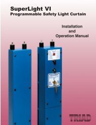
SUPERLIGHT<br />
VI<br />
PROGRAMMABLE SAFETY LIGHT CURTAIN<br />
Featuring the “QuickView Diagnostic Display”<br />
For <strong>Inc</strong>reased Productivity and Maximum Operator Safety<br />
AMERICA’S MACHINE GUARDING/MACHINE CONTROL COMPANY<br />
<strong>Triad</strong> <strong>Controls</strong>, <strong>Inc</strong>.<br />
3
SUPERLIGHT<br />
VI<br />
The Ultimate in Safety–Quality–Value<br />
Diverse Redundancy Design<br />
Concept<br />
<strong>Triad</strong> safety light curtains utilize the<br />
diverse redundancy design concept.<br />
This gives the safety light system a<br />
higher level of redundancy and<br />
control reliability. The two<br />
microprocessors are of different<br />
design, and the microprocessor or<br />
parallel programs are run and made<br />
up from different instruction sets<br />
written by different programmers.<br />
Self-Checking Circuitry<br />
<strong>Triad</strong> safety light curtains self-check<br />
every 20 milliseconds. Self-checking<br />
is the ability to electronically verify<br />
that all of the system’s critical<br />
internal circuit components and their<br />
redundant counterparts or back-ups<br />
are operating properly.<br />
Extra Safe Design<br />
Provides two methods of fail-safe<br />
design. One utilizes two<br />
microprocessors and two captive<br />
contact relays, and one uses four<br />
watchdog timers monitoring the<br />
system and the captive contact<br />
relays.<br />
Redundant Captive Contact<br />
Safety Relays<br />
Redundant relays assure safety if an<br />
output relay should fail. SuperLight<br />
VI utilizes safety relays which have<br />
force-guided contacts. The contacts<br />
are mechanically locked together so<br />
that if one set of contacts weld, the<br />
other contacts cannot change state.<br />
External Diagnostic Display<br />
Standard on all <strong>Triad</strong> safety light<br />
curtains is the "Quickview Diagnostic<br />
Display." The alphanumeric display<br />
shows status and fault codes of the unit.<br />
This is an excellent safety and<br />
maintenance feature.<br />
Control Reliable System<br />
Critical components of the SuperLight<br />
VI are duplicated so that a single<br />
component failure will not cause an<br />
unsafe condition. If a component does<br />
fail, the unit’s self-checking circuitry<br />
recognizes the situation and initiates a<br />
safe stop of the machine.<br />
Powerful Infrared Light Source<br />
<strong>Triad</strong> safety light curtains utilize<br />
powerful, safe, and predictable infrared<br />
light as its sensing source. This gives<br />
the system greater reliability and<br />
enhances machine utilization by<br />
minimizing nuisance trips and<br />
shutdowns caused by dirt, coolants,<br />
lubrication mists, and machine oils.<br />
<strong>Triad</strong> safety light curtains are highly<br />
immune to EMI, RFI, and ambient light<br />
conditions, and are unaffected by strobe<br />
lights, and weld flash generated light<br />
sources.<br />
Extensive Testing<br />
<strong>Triad</strong> safety light curtains incorporate<br />
extensive testing and burn-in to<br />
establish a high degree of product<br />
reliability and safety.<br />
Emitter<br />
Receiver<br />
Standard Features and Capabilities<br />
• Cost competitive<br />
• Very easy to align and install<br />
• Three-Year warranty (industry leader)<br />
• Heavy duty aluminum welded 14 gauge<br />
enclosure<br />
• Dust and oil tight<br />
• 3/4" infrared light beam spacing<br />
• External status and diagnostic display on all<br />
light curtains<br />
• Compact design<br />
• Single/multiple floating beam blanking<br />
• Single/multiple fixed beam blanking<br />
• Auto-Blanking feature option<br />
• PSDI-Presence Sensing Device Initiation<br />
capability option<br />
4<br />
• Alignment indicator light<br />
• Shock mounts supplied standard<br />
• Easy access for wiring<br />
• Dual self-checking captive contact safety<br />
relays<br />
• Fast reacting-Less than 30 ms all sizes<br />
• Light curtain controller box not required<br />
• Light curtain interconnections not required<br />
between pylons or a third box or controller<br />
• Non-mated units, matched sets are not<br />
required<br />
• 2-, 3-, 4- or 5-sided protection available with<br />
mirrors<br />
• Extended scanning ranges available —<br />
75' (22.8m) maximum<br />
• Dual independent channel microprocessor<br />
design<br />
• Self-checking circuitry<br />
• Nine standard sizes — 12" (305mm) to<br />
72" (1829mm) lengths<br />
• Meets or exceeds OSHA, ANSI, CSA, and<br />
RIA standards<br />
• Not affected by ambient light<br />
• High immunity to EMI and RFI noise sources<br />
• High immunity to strobe type and weld flash<br />
generated light sources<br />
• Interfaces easily with all types of machine<br />
controllers and PLCs<br />
• Made in the U.S.A
Standard on all <strong>Triad</strong> safety light curtains<br />
is the revolutionary front panel diagnostic<br />
display. The bright red alphanumeric LED<br />
display shows the status of the safety<br />
light curtain along with various integral<br />
fault codes relating to the maintenance<br />
and operation of the system.<br />
The diagnostic display monitors<br />
microprocessors, captive contact safety<br />
relays, bad grounds, external infrared<br />
sources, shorts, blanking, etc. Fault<br />
Quickview Diagnostic Display<br />
conditions are easily read and displayed<br />
on the top front panel of the receiver<br />
pylon. These easy to read external<br />
diagnostic codes and status displays will<br />
enhance safety and machine utilization by<br />
minimizing machine downtime and set-up<br />
time measurably<br />
The advanced design of the SuperLight<br />
VI diagnostics will also count and display<br />
the number of beams blanked out in the<br />
"Auto-Blank" mode. This is an important<br />
SUPERLIGHT<br />
VI<br />
feature when computing the depth<br />
penetration factor required for proper<br />
installation.<br />
A detailed definition, status, reason(s),<br />
and cure listing is provided within the<br />
installation and operation manual of each<br />
<strong>Triad</strong> safety light curtain.<br />
DECIMAL POINTS OFF<br />
0 = Clear<br />
1-4 = Blocked<br />
5-6 = Relay Fault<br />
AUTO Blank *<br />
*7 = Active<br />
*8 = Missing/too large<br />
9 = Ram Failure<br />
A = Master cannot talk to<br />
slave microprocessor<br />
B = Data disagreement<br />
with slave unit<br />
C = External infrared<br />
source detected<br />
D = Internal short/open<br />
E = Beam selection error<br />
F = Bad computer clock<br />
DIAGNOSTIC<br />
DISPLAY<br />
DECIMAL POINTS ON<br />
.0. = Clear<br />
.1. = 1 beam blocked<br />
.2. = 2 beams blocked<br />
.3. = 3 beams blocked<br />
.4. = 4 beams blocked<br />
.5. = 5 beams blocked<br />
.6. = 6 beams blocked<br />
.7. = 7 beams blocked<br />
.8. = 8 beams blocked<br />
.9. = 9 beams blocked<br />
.A.<br />
.B.<br />
.C.<br />
.D.<br />
.E.<br />
.F.<br />
= 10 beams blocked<br />
= 11 beams blocked<br />
= 12 beams blocked<br />
= 13 beams blocked<br />
= 14 beams blocked<br />
= 15 beams blocked<br />
Subject Machine Control Reliability Requirements<br />
Applications<br />
Control reliability control circuits shall be<br />
designed and constructed so that a single<br />
failure or fault within the system does not<br />
prevent the normal stopping action from<br />
being applied to the press when required<br />
or does not create an unintended stroking<br />
action but does prevent initiation of a<br />
successive stroke until the failure is<br />
corrected (ANSI B11.1-2001). Always<br />
refer to the specific ANSI or OSHA code<br />
for the complete requirements of the<br />
subject machine.<br />
The <strong>Triad</strong> infrared safety light curtain is<br />
suited for air clutch, hydraulic, and<br />
pneumatic equipment such as punch<br />
presses, mechanical, pneumatic and<br />
hydraulic press brakes, injection molding<br />
machines, die casting operations,<br />
powered metal compacting presses, filter<br />
presses, automatic assembly equipment,<br />
bending rolls, robotic operations, FMS<br />
systems, slitting lines and food<br />
processing machinery.<br />
5
SUPERLIGHT<br />
VI<br />
Blanking Options<br />
The most complete format of blanking options available in the industry<br />
Select the style best suited for your applications<br />
Auto-Blanking - (AB) Option<br />
AUTO BLANKING TM<br />
TO PROGRAM:<br />
MOVE KEYSWITCH FROM RESET POSITION INTO AUTO BLANK<br />
POSITION WHILE DESIRED OBJECT BLOCKS LIGHT CURTAIN CODE 7<br />
INDICATES AUTO BLANK ACTIVATED<br />
OFF<br />
RESET<br />
MODE 1<br />
MUST BE<br />
RESET IF<br />
AUTO BLANK<br />
OBSTRUCTION<br />
MOVES OR GUARD<br />
PENETRATED<br />
MODE 3<br />
MODE 2 WITH<br />
FLOATING BLANK<br />
MODE 2<br />
MUST BE<br />
RESET IF<br />
AUTO BLANK<br />
OBSTRUCTION<br />
MOVES<br />
PATENTED<br />
<strong>Triad</strong>'s advanced "Auto-Blank" option is unique because it will automatically blank<br />
out only the required number of beams needed to accept an obstruction such as a<br />
conveyor, bracket or fixture. The unit is easily programmed by a supervisory<br />
controlled four position keyed selector switch located on the front panel of the<br />
receiver pylon (shown left). The "Auto-Blank" method of blanking is much safer<br />
than DIP switch or master/slave blanking systems because only the area of the<br />
obstruction will be blanked. This feature prohibits unsafe oversizing of the blanked<br />
area commonly found throughout industry on manually blanked systems. "Auto-<br />
Blank" also eliminates the need to count beams and to locate where and what<br />
beams are to be shut off to obtain the correct beam elevation to accept an<br />
obstruction. "Auto-Blank" will also watch the obstruction and, if it moves or is<br />
removed, will go into a "machine stop mode" to prevent further machine operation.<br />
This is an additional safety feature not available on manually blanked units. These<br />
features truly enhance production while providing the ultimate in safety.<br />
When the key switch is turned to the "Auto-Blank" function, the "Quickview<br />
Diagnostic Display" will show the number of blocked beams for two seconds, then<br />
verify that the obstruction is being monitored. This is required information for the<br />
depth penetration factor and for proper installation of any safety light curtain.<br />
The versatile "Auto-Blank" (AB) Blanking Series includes:<br />
• Constant scan light curtain<br />
• One Beam Floating Blank built-in plus "Auto-Blank" capability<br />
• Two "Auto-Blank" Modes - up to 8 beams blanked but need not be<br />
sequential<br />
A. One "Auto-Blank" mode with keyed reset when guarded zone<br />
is penetrated<br />
B. One "Auto-Blank" mode with automatic reset when guarded<br />
zone is penetrated.<br />
Floating Blank - (8K) Option<br />
FLOATING BLANK<br />
4 cm<br />
2 cm<br />
6 cm<br />
8 cm<br />
The "Floating Blank" option provides the flexibility necessary to ef fectively guard all<br />
types of equipment that require multiple floating beams. This is quite common in<br />
the fabricating industry where the workpiece moves.<br />
The "Floating Blank" permits work pieces to be formed vertically or horizontally<br />
through the guarded area without shutting down the machine. Entry into the<br />
protected area by the operator or passerby will prevent the start or, if the machine<br />
is in motion, will provide a signal to stop the machine.<br />
The "Floating Blank" is controlled by a keyed selector switch that will allow a work<br />
opening of 8cm based on 2cm increments (shown left). Blanking adjustments<br />
required when die heights change are not necessary. The "Floating Blank" light<br />
curtain automatically adjusts to the various feed positions providing production<br />
with protection.<br />
The "Floating Blank" (8K) Option includes:<br />
• 2cm - Constant scan light curtain<br />
• 4cm - One floating beam<br />
• 6cm - Two floating beams<br />
• 8cm - Three floating beams<br />
6
SUPERLIGHT<br />
VI<br />
Specifications-Dimensions-Ordering Procedure<br />
Specifications<br />
All Models<br />
Dim A<br />
Dim B<br />
Dim C<br />
Dim D<br />
Dim E<br />
Dim F<br />
Dim G<br />
Dim I<br />
Dim J<br />
Dim M<br />
3.00” (76mm)<br />
4.25” (108mm)<br />
1.00” (25mm)<br />
1.87” (48mm)<br />
0.62” (16mm)<br />
1.00” (25mm)<br />
1.00” (25mm)<br />
3.25” (83mm)<br />
0.62” (16mm)<br />
4.25” (108mm) (TR-12 is 5.25” or 133mm)<br />
Model Dim H (box length) Dim K (last to end) Dim L (first to last beam)<br />
TR/TPG-12 16.37” (416mm) 1.87” (48mm) 12.62” (321mm)<br />
TR/TPG-18 22.62” (575mm) 1.87” (48mm) 18.92” (481mm)<br />
TR/TPG-24 28.87” (733mm) 1.87” (48mm) 25.22” (641mm)<br />
TR/TPG-30 36.25” (921mm) 2.87” (73mm) 31.52” (801mm)<br />
TR/TPG-36 42.12” (1070mm) 2.87” (73mm) 37.82” (961mm)<br />
TR/TPG-42 48.37” (1229mm) 2.87” (73mm) 44.12” (1121mm)<br />
TR/TPG-48 54.75” (1391mm) 2.87” (73mm) 50.42” (1281mm)<br />
TR/TPG-60 67.25” (1708mm) 2.87” (73mm) 63.02” (1601mm)<br />
TR/TPG-72 79.75” (2026mm) 2.87” (73mm) 75.62” (1921mm)<br />
TR/TPG-84 91.75” (2330mm) 2.87” (73mm) 88.22” (2241mm)<br />
TR/TPG-96 103.75” (2635mm) 2.87” (73mm) 100.82” (2561mm)<br />
For 12” (305mm) to 36” (914mm) units with 3/4” (19mm) beam spacing<br />
1. Specify height of unit<br />
2. Type of unit 2F, 4F, 8K, AB<br />
3. Total distance to be scanned (must be specified)<br />
TR - 12 - 2F - 00<br />
SuperLight VI<br />
Prefix<br />
Scanning Height<br />
in <strong>Inc</strong>hes<br />
Type of Unit<br />
2F No Floating Blank or Blanking Beams<br />
constant scan<br />
4F One beam built-in Floating Blank<br />
capability<br />
8K Up to 3 beam Floating Blank<br />
adjustable by use of keyswitch<br />
removable in all positions on receiver<br />
pylon. Capable of constant scan, one,<br />
two or three floating beams.<br />
AB Constant scan light curtain;<br />
One beam floating blank<br />
Two Auto-Blank Modes<br />
For 42” (1067mm) to 72” (1829mm) units with 1 1/2” (38mm) beam spacing<br />
1. Specify height of unit<br />
2. Type of unit 4CM, 4F, AB<br />
3. Total distance to be scanned (must be specified)<br />
SuperLight VI<br />
Prefix<br />
Ordering Procedure<br />
Approximate<br />
distance light<br />
curtain is to scan<br />
in feet<br />
TR - 42 - 4CM - 00<br />
Scanning Height<br />
Type of Unit<br />
in <strong>Inc</strong>hes 4cm 4cm spacing with constant scan<br />
4F 4cm spacing with one floating blank<br />
AB Constant scan Model 4cm;<br />
One beam floating blank built-in<br />
Two Auto-Blank modes<br />
Approximate<br />
distance light<br />
curtain is to Scan<br />
in Feet<br />
• Power Requirements: 120VAC +/- 10% @<br />
50-60 Hz with fuse protection (24VDC units<br />
optional)<br />
• Power Consumption: 24 watts total<br />
• Infrared Light Source: Solid state light<br />
emitting diodes<br />
• Beam Spacing: 3/4"(19mm); 1-1/2" (38mm)<br />
for Models TR-48 through TR-72<br />
• Response Time: Less than 30 milliseconds<br />
(All sizes)<br />
• Relay Contact Ratings: 8 AMP rating @<br />
220VAC; 16 AMP rating @ 120VAC<br />
• Relay Configuration: Dual captive contact<br />
self-checking safety relays.<br />
• Minimum Object Sensitivity: 1-1/4"<br />
(32mm); 2" (51mm) for Models TR-48<br />
through TR-72<br />
• External Alphanumeric Diagnostic and<br />
Status Display<br />
• Temperature Range: 32 degrees to 120<br />
degrees F<br />
• Scanning Frequency: 3.6 Khz<br />
• Shock: Tested to withstand high vibration<br />
applications.<br />
• Self-checking every 20 milliseconds.<br />
• Indicators: Red obstruction light on<br />
receiver. Green non-obstruction light on<br />
receiver. Red alignment indicator light on<br />
emitter.<br />
• Construction: Heavy duty aluminum<br />
enclosure (all welded). 14 Gauge - Dust and<br />
oil tight. NEMA 12<br />
• Scanning Distance: All units are supplied<br />
standard with a 20' (6.1m) scanning<br />
capability. Extended range units are<br />
available, consult your representative or the<br />
factory. Scanning distances must be<br />
specified — 75' (23m) maximum.<br />
• Specials: Custom designed light curtains for<br />
special applications. Examples: L-shaped,<br />
stainless steel. Consult factory.<br />
• CSA Approved, UL Pending<br />
• Three-Year Warranty<br />
Light Curtain Options<br />
Auxiliary Output Contact: Provides an<br />
isolated (dry) contact output to be used as a<br />
signal line. Specify NO or NC output. Add<br />
suffix AO to light curtain Model Number .<br />
Cincinnati Interface/Forced Interrupt:<br />
Allows an external device (i.e., Cincinnati<br />
Press or PLC) to initiate a Red Condition on<br />
the light curtain. This option is required on<br />
machines that feed a 24VDC signal back to<br />
the safety light curtain to assure that the safety<br />
control circuit can be shut down. Add suffix CI<br />
to light curtain Model Number.<br />
External Relay Check: This option monitors<br />
the control relays of the guarded machine to<br />
assure that the machine control relays change<br />
state when the safety light curtain sends a stop<br />
signal. Add suffix ER to light curtain Model<br />
Number.<br />
Resettable Latching Relays: Requires the<br />
light curtain to be manually reset every time<br />
the light curtain is penetrated. Add suffix LR to<br />
light curtain Model Number.<br />
24VDC Power Source: Add suffix DC to light<br />
curtain Model Number.<br />
7
Accessories<br />
Cornering Mirror Dimensions Pedestal Dimensions (Model 8000)<br />
Through the use of cornering mirrors, multiple sides or work<br />
envelopes can be guarded which enhance safety and reduce downtime<br />
related to mechanical and electrical interlock systems.<br />
<strong>Inc</strong>lude a 5% reflectivity loss per mirror when calculating total<br />
scanning distance of light curtain.<br />
NOTE: Mirrors are surface coated. Wipe surface using only a damp,<br />
clean, soft 100% cotton cloth. To replace: remove the end bracket,<br />
slide out the mirror with the gasket.<br />
Model Dim A (hole to hole) Dim B (mirror) Dim C (total)<br />
TRM-12 19.45" (494mm) 18.25" (464mm) 20.50" (521mm)<br />
TRM-18 25.45" (646mm) 24.25" (616mm) 26.50" (673mm)<br />
TRM-24 31.45" (799mm) 30.25" (768mm) 32.50" (825mm)<br />
TRM-30 37.45" (951mm) 36.25" (921mm) 38.50" (978mm)<br />
TRM-36 43.45" (1104mm) 42.25" (1073mm) 44.50" (1130mm)<br />
TRM-42 49.45" (1256mm) 48.25" (1226mm) 50.50" (1282mm)<br />
TRM-48 55.45" (1408mm) 54.25" (1378mm) 56.50" (1435mm)<br />
TRM-60 67.45" (1713mm) 66.25" (1683mm) 68.50" (1739mm)<br />
TRM-72 79.45" (2018mm) 78.25" (1988mm) 80.50" (2045mm)<br />
The heavy duty, all welded steel pedestal floor mounts can be used<br />
for mounting either the SuperLight VI system or cornering mirrors.<br />
Sliding mounts on the pedestal are of universal design and are<br />
supplied standard. Unique floating base on pedestal is designed to<br />
compensate for uneven floors.<br />
Pedestals must be bolted to the floor, they must not be movable<br />
(ANSI B11.19-1990)<br />
1) Sliding Mounts supplied<br />
2) Standard height - 72" (1829mm) - Model 8000<br />
Optional height - 96" (2438mm) - Model 8096<br />
3) Painted OSHA yellow<br />
4) Pedestal - 12 gauge steel<br />
Base Plate - 1/4" (6mm) steel plate<br />
Model 9000 Swing Mount Brackets<br />
Excellent method of mounting light guard for press brakes or when<br />
light guard is to be moved for die setups or machine maintenance.<br />
Model 9000 consists of three 180° pivot points along with light guard<br />
diagonal movement capability for virtually unlimited light guard<br />
positioning. Two-inch square tubing 3/16" (5mm) thick painted OSHA<br />
yellow which mounts directly onto the machine housing and makes for<br />
a heavy duty yet versatile mounting bracket.<br />
Specify dimensions “B” & “C”<br />
Ordering Procedure:<br />
Specify Pedestal Model # and Quantity.<br />
• Specify Model 9000 Swing Mount Brackets and quantity.<br />
• Specify B & C dimensions required.<br />
• Specify light curtain or mirror size to be mounted.<br />
8
Applications<br />
Punch Presses<br />
Robotic and Automation<br />
Multi-Sided Guarding System<br />
Easily installed cornering mirrors combined<br />
with the easy alignment characteristics of the<br />
SuperLight VI provide multi-sided protection<br />
which allows complete visibility and access to<br />
the protected pinch point or hazardous zone for<br />
a fraction of the cost of physical barriers.<br />
Light Curtain<br />
Emitter<br />
Light Curtain<br />
Receiver<br />
The SuperLight VI is designed to<br />
accept coil stock movement with no<br />
press shutdowns or adjustments to<br />
light guard. No adjustments necessary<br />
to light guard for die height changes or<br />
changes from automatic to hand fed<br />
secondary operations.<br />
Infrared<br />
Light Curtain<br />
Pinch Point<br />
or<br />
Hazardous Area<br />
Cornering<br />
Mirrors<br />
Press Brakes<br />
<strong>Triad</strong> SuperLight VI infrared light curtain<br />
now designed for power press brakes,<br />
utilizing the Floating Blank series.<br />
How Floating Blank Works:<br />
The <strong>Triad</strong> Floating Blank light curtain<br />
provides the flexibility necessary to<br />
effectively guard all types of power press<br />
brakes. The Floating Blank permits work<br />
pieces to be formed vertically or<br />
horizontally through the guarded area<br />
without shutting down the machine. Entry<br />
into the protected area by the operator or<br />
passerby will prevent the start or, if the<br />
machine is in motion, will provide a signal<br />
to stop the machine.<br />
While other safety devices must be<br />
altered to allow materials to feed through,<br />
the Floating Blank is controlled by a<br />
keyed selector switch that will allow a<br />
work opening of up to 8cm based on 2cm<br />
increments.<br />
Blanking adjustments required when die<br />
heights change are not necessary. The<br />
Floating Blank light curtain automatically<br />
adjusts to the various feed positions<br />
providing production with protection. The<br />
Floating Blank light curtain adapts to<br />
mechanical, air clutch, and hydraulic<br />
press brakes.<br />
<strong>Triad</strong> <strong>Controls</strong> Muting Kit - <strong>Triad</strong> Package #130 Automatic Tripping - PSDI<br />
<strong>Triad</strong> <strong>Controls</strong> manufacturers a complete line<br />
of standard and customized machine guards<br />
and controls for safety and increased<br />
productivity. Control systems are control<br />
reliable and available in both solid state or<br />
relay logic. <strong>Controls</strong> meet or exceed OSHA<br />
regulation 1910.217 and ANSI standards<br />
B11.1-2001, B11.19-1990 for control reliability<br />
and component monitoring.<br />
<strong>Triad</strong> SuperLight VI barriers can be bypassed<br />
during non-hazardous portions of machine<br />
operation. Ideal for press operations where<br />
parts or scrap are being ejected or during<br />
hand removal of parts on the upstroke of the<br />
machine. Reference <strong>Triad</strong> Package #130 PB<br />
for Press Brakes. Always submit the<br />
machine electrical schematic for proper point<br />
of interface.<br />
Presence Sensing Device Initiation<br />
Certification must be obtained for proper<br />
application of this optional feature. Refer to<br />
the specific OSHA or ANSI standard related<br />
to the subject machine on which PSDI is to<br />
be applied.<br />
9
Mute-Out Packages<br />
for Press Brake Control Systems<br />
Safety and <strong>Controls</strong><br />
<strong>Triad</strong> Mute-Out Package #130<br />
Operational Description - Package #130<br />
The Mute-Out Package #130 has been designed to allow the<br />
SuperLight VI or VII infrared light curtain to be muted out or bypassed<br />
during the non-hazardous portion of the machine cycle.<br />
The mute-out function is actuated by the No. 301 limit switch<br />
and the No. 300 adjustable calibrated switch actuator when the<br />
die is within 1/4" (6.35mm) of the pinch point and continues<br />
until the ram returns to top stop. At this point the infrared light<br />
curtain reactivates and gives protection during the hazardous<br />
portion of the downstroke.<br />
Punch Presses - Reference Package #130 PP<br />
Package #130PP enhances productivity on punch presses<br />
because parts can be loaded or unloaded during the non<br />
hazardous upstroke or to be used when parts are ejected<br />
through the light curtain on the upstroke. Always submit<br />
machine electrical schematics to assure proper point of<br />
interface. Specify air clutch or hydraulic machine application.<br />
Press Brakes - Reference Package #130 PB<br />
Package #130PB interfaces directly on air clutch and hydraulic<br />
press brakes when these machines have control reliability and<br />
component monitoring. The mute out function is activated by<br />
the calibrated switch actuator No. 300 and gives the operator<br />
the capability to work with small parts and workpieces that<br />
have flanges. Always submit machine electrical schematics to<br />
assure proper point of interface. Specify air clutch or hydraulic<br />
machine application. Add suffix AC for air clutch press brake or<br />
suffix HV for hydraulic press brake.<br />
Select-O-Stop (Option for Package #130PB)<br />
Select-O-Stop is an option for Package #130PB. Select-O-<br />
Stop is a keyed function (on/off) that is activated by the<br />
calibrated switch actuator mounted on the side of the ram.<br />
Select-O-Stop will allow the operator to bring the ram down at<br />
a fast speed to a preset position which is 1/4" (6.35mm) above<br />
the material to be formed. At this point the ram will stop and<br />
then the light curtain mute out will begin. The Select-O-Stop<br />
function is ideal for small part forming or realignment of the<br />
work piece. Add suffix SOS to Package #130PB for this<br />
feature.<br />
10
Safety and <strong>Controls</strong><br />
Press Brake <strong>Controls</strong><br />
11
Press Brake <strong>Controls</strong><br />
Safety and <strong>Controls</strong><br />
Safety and <strong>Controls</strong><br />
<strong>Triad</strong> SuperLight VI<br />
Infrared Light Curtain<br />
now designed for<br />
Power Press Brakes,<br />
Utilizing the Floating Blank series<br />
How the Floating Blank Works:<br />
The <strong>Triad</strong> Floating Blank light curtain provides the flexibility<br />
necessary to effectively guard all types of power press<br />
brakes. The Floating Blank permits work pieces to be formed<br />
vertically or horizontally through the guarded area without<br />
shutting the machine down. Entry into the protected area by<br />
the operator or passerby will prevent the start or, if the<br />
machine is in motion, will provide a signal to stop the<br />
machine.<br />
While other safety devices must be altered to allow materials<br />
to be fed through, the Floating Blank is controlled by a keyed<br />
selector switch that will allow a work opening of 8 cm based<br />
on 2 cm increments. Blanking adjustments required when die<br />
heights change are not necessary. The Floating Blank<br />
automatically adjusts to the various feed positions providing<br />
production with protection. The Floating Blank light curtain<br />
adapts to mechanical, air clutch, and hydraulic press brakes.<br />
Refer to Pages 13 through 26 for proper press brake controls.<br />
Refer to pages 3 through 9 for complete SuperLight VI specifications.<br />
12
Safety and <strong>Controls</strong> Safety and <strong>Controls</strong><br />
Press e Guarding Brake and <strong>Controls</strong><br />
ols<br />
Press Brak<br />
ake Guar<br />
Guideline to Proper Equipment Selection<br />
Introduction - Due to the interaction required between the operator , workpiece, and the point of operation, press brake<br />
guarding requires versatility with both the press brake control system along with flexibility in the point of operation guarding<br />
device. Production can be had with the protection only when the guards and controls put on a machine are properly designed<br />
to match the operational procedures your shop may dictate; may it be a short run multiple die change job shop to the needs<br />
of a high volume long run production shop. The following packages incorporate features and functions to address the many<br />
needs of the industry based on our many years of experience in the metal stamping and metal forming industries.<br />
OSHA & ANSI Standards:<br />
OSHA (Occupational Safety & Health Act) - Federal Register Sub-Part O, 1910.212.<br />
ANSI - American National Standard B11.1-2001.<br />
Press Brake<br />
Classification<br />
Mechanical<br />
Partial revolution clutch-mechanical<br />
friction-currently uses mechanical<br />
pedal to actuate press brake<br />
Air Clutch<br />
Partial revolution clutch-uses<br />
electric foot switch to actuate press<br />
With updated controls<br />
Hydraulic/Hydro Mechanical<br />
SELECT ONE<br />
Press Brake Control Options<br />
Package #2100-Converts to electric foot switch<br />
and incorporates automatic slow forming. When<br />
optional ram indexing modes are added, system<br />
is excellent for the high production shop.<br />
Updates controls for control reliability and<br />
component monitoring.<br />
Package #1-Retains current mechanical foot<br />
treadle to retain operator feel for slow forming.<br />
Excellent for brakes working in the top end of<br />
the tonnage spectrum. Updates controls for<br />
control reliability and component monitoring.<br />
Package #2101-<strong>Inc</strong>orporates the two-hand/foot<br />
method of press brake control. Works well for<br />
the low volume job shop press brake. Updates<br />
the controls for control reliability and component<br />
monitoring.<br />
Package #2110-Converts the mechanical press<br />
brake to electric foot switch and incorporates a<br />
single forming speed. This package is used for<br />
press brakes used as punch presses. Updates<br />
the controls to meet current OSHA standards<br />
for control reliability and component monitoring.<br />
Package #2120-Updates control to meet current<br />
OSHA standards for control reliability and<br />
component monitoring.<br />
Package #3122-Updates control to meet current<br />
OSHA standards for control reliability and<br />
component monitoring. This control<br />
incorporates the two-hand/foot method of<br />
control and guarding.<br />
Package #130 PB Mute-Out-When an air clutch<br />
press brake meets current standards for control<br />
reliability and component monitoring, package<br />
#130 PB interfaces directly with the existing<br />
controls to mute-out the infrared light guard on<br />
the non-hazardous portion of the stroke.<br />
Package #130 PB Mute-Out-When a hydraulic<br />
press brake meets current standards for control<br />
reliability and component monitoring, package<br />
#130 PB interfaces directly with the existing<br />
controls to mute-out the infrared light guard on<br />
the non-hazardous portion of the stroke.<br />
Package #4101-Gives the hydraulic press brake<br />
the two-hand/foot method of guarding the point<br />
of operation. Same operational description as<br />
packages #2101 or #3122. Submit schematic<br />
for proper point of interface.<br />
SELECT ONE<br />
Point of Operation<br />
Guarding Options<br />
• SuperLight VI Floating Blank<br />
infrared light curtain<br />
• SuperLight VI Floating Blank<br />
infrared light curtain only.<br />
• Utilizes two hand controls<br />
included in package.<br />
• SuperLight VI Floating Blank<br />
infrared light curtain.<br />
• Two Hand <strong>Controls</strong><br />
• SuperLight VI Floating Blank<br />
infrared light curtain.<br />
• Two Hand <strong>Controls</strong><br />
• Utilizes two hand controls<br />
included in package.<br />
• SuperLight VI Floating Blank<br />
infrared light curtain.<br />
• SuperLight VI Floating Blank<br />
infrared light curtain.<br />
• Two Hand <strong>Controls</strong><br />
13
Press Brake <strong>Controls</strong><br />
Safety and <strong>Controls</strong><br />
Mechanical Press Brake Control with Automatic Slow Forming<br />
Pac<br />
acka<br />
kage 2100<br />
Package 2100 incorporates single stroke function with<br />
Select-O-Stop and ram control functions. This converts<br />
mechanically actuated press brakes to electrical foot switch<br />
actuation and gives the press brake automatic slow forming<br />
capability. Excellent for the long run and small piece part<br />
production shop where uniform piece part forming is<br />
required. Meets current OSHA standards for control<br />
reliability and component monitoring and also incorporates<br />
brake monitoring.<br />
Model 3400SS (Solid State) Control System<br />
Components<br />
#302<br />
#303<br />
#300<br />
#301<br />
#311<br />
Package 2100 includes the following:<br />
Model 3400SS (Solid State) Control System<br />
• Control reliable design<br />
• Diverse redundant design concept<br />
• Quickview diagnostic message display<br />
• Interrupted stroke provision<br />
• System logic and component diagnostics<br />
• Redundant captive contact safety relays<br />
• Control incorporates cross-checking, self checking, and<br />
diverse redundancy<br />
• Control transformer (reduces voltage from 480/260 to<br />
120VAC)<br />
• Power interlock<br />
• NEMA 12 enclosure<br />
• Brake monitor top stop indicator<br />
• Ground fault indicator<br />
• Keyed selector switch for two hand/foot mode of<br />
operation<br />
• System on illuminated indicator light<br />
• System start guarded push button<br />
• System stop unguarded push button<br />
• Keyed selector switch for Select-O-Stop Function on/off<br />
• Control design writing<br />
• <strong>Inc</strong>orporates light curtain mute-out<br />
• Light curtain interface (optional)<br />
#306<br />
#305<br />
No. UL-102 UltraTouch Modules (optional)<br />
No. 300 Calibrated Switch Actuator (Activates Select-O-Stop)<br />
No. 301 Limit Switches (four)<br />
No. 302 Guarded Foot Switch<br />
No. 303 Dual Solenoid Valve with Muffler<br />
No. 305 Ram Control Cylinder Assembly<br />
No. 306 Heavy Duty Pressure Switch<br />
No. 311 Filter, Regulator, Lubricator<br />
A proper point of operation guarding device is required when using the<br />
electric foot switch as the activating device. Refer to Pages 3 through 9<br />
for details.<br />
14
Safety and <strong>Controls</strong><br />
Press Brake <strong>Controls</strong><br />
Mechanical Press Brake Control with Automatic Slow Forming<br />
Ram Control Cylinder Assembly–No. 305 (Press Brake Applications)<br />
The <strong>Triad</strong> Ram Control incorporates a No. 305 ram control cylinder<br />
assembly into the Model 3400 control system to provide a slow speed<br />
feature on mechanically actuated, friction clutch press brakes. This<br />
allows the operator to automatically slow-form a part to prevent damage<br />
to the part and to prevent potential injury due to part "whipping up"<br />
during the forming. When equipped with the <strong>Triad</strong> Ram Control, the<br />
ram advances to a predetermined position above the work with the<br />
clutch fully engaged (fast down). At this point, the ram will stop, allowing<br />
for realignment of the part before forming. The foot switch is then<br />
actuated a second time and the ram will advance slowly , forming the<br />
part and then return to the top of the stroke at a high speed (fast return).<br />
The Ram Control can be adjusted to provide the best speed for the<br />
part being formed.<br />
Automatic Ram Cycling and Indexing Options<br />
Auto Cycle — All systems are designed for single stroke only . Auto<br />
Cycle allows the press to continue past top stop as long as the operator<br />
has maintained foot pedal contact and stops at the Select-O-Stop<br />
position. AutoCycle may only be used with a light curtain, which will<br />
prevent the press from continuing past top stop, if the operator has<br />
his/her hand in the die area when the press reaches top stroke.<br />
Excellent for the production of small parts on press brakes and<br />
workpieces with flanges.<br />
Auto Retrip — When Select-O-Stop has been turned on, the press will<br />
automatically stop at a preset point, which is normally set just above<br />
the piece part to be formed. The operator then has to release the pedal<br />
and depress it to continue the forming cycle. The Auto Retrip function<br />
will automatically restart the press at that point, as long as the operator<br />
maintains foot pedal contact. Excellent for large sheet forming.<br />
Auto Form — While controlling the forming speed of a piece part, it<br />
sometimes is necessary to fully engage the clutch, just prior to the<br />
bottom of the stroke, to obtain a desired radius with the die being used.<br />
Auto Form will bypass the feed cylinder at that point, allowing full<br />
engagement of the clutch and preventing the possibility of a stall at the<br />
bottom of the stroke. Excellent for top end tonnage forming on press<br />
brakes.<br />
Auto Return — Press will automatically return to top of stroke after<br />
piece part has been formed (requires additional limit switch). This<br />
feature enhances ram cycling.<br />
Select-O-Stop function is activated by the calibrated switch actuator which<br />
is mounted on the side of the ram. Select-O-Stop allows the operator to<br />
bring the ram down to a preset position which is 1/4" (6.35mm) above the<br />
material being formed and will automatically stop the ram. This gives the<br />
operator the opportunity to realign the work piece and then slow form the<br />
workpiece if desired. Select-O-Stop is a keyed function on/off on the main<br />
control panel.<br />
Light Curtain Mute-Out automatically bypasses light curtain when die has<br />
reached piece part and point of operation hazard no longer exists. Light<br />
curtain is automatically reactivated when press reaches top of stroke to<br />
prevent operator from being in point of operation during the hazardous<br />
downstroke of the press. This feature is only used when a light curtain is<br />
used as the point of operation guarding device.<br />
Ordering Procedure (Package 2100)<br />
❏ Manufacturer of Press Brake _________________ Model _______________ Serial #_________<br />
Bed Length ___________<br />
❏ Voltage ___________Cycle _________________ Phase ________________<br />
OPTIONS<br />
❏ Electro--mechanical relay system (RL) instead of solid state (SS) control.<br />
❏ Motor H.P. if magnetic starter desired (Main Motor) ___ Full Load Amps ___ Rev. or Non-Rev.<br />
❏ Motor H.P. if magnetic starter desired (Ram Motor) ____ Full Load Amps ___ Rev. or Non-Rev.<br />
❏ Main Power fused electrical disconnect switch --- Yes ____ No ____<br />
❏ Rotary cam, sprockets, and chain to replace two limit switches<br />
PRODUCTION FUNCTIONS DESIRED<br />
❏ Auto Cycle is a keyed function on control panel on/off (can only be used with a light curtain)<br />
❏ Auto Retrip is a keyed function on control panel on/off<br />
❏ Auto Form is a keyed function on control panel on/off<br />
❏ Auto Return is a keyed function on control panel on/off (requires additional limit switch)<br />
❏ SuperLight VI infrared light curtain model __________________ (requires light curtain interface on control panel if light<br />
curtain is used)<br />
❏ Light Curtain Mounting Brackets<br />
❏ Model 8000 Pedestal Mounts. Refer to Page 28 for details.<br />
❏ Model 9000 Swing Mounting Brackets. Refer to Page 28 for details.<br />
❏ Model BM-1600 Time-Based Brake Monitor. Consult Factory.<br />
❏ Specify any additional options desired but not shown.<br />
15
Press Brake <strong>Controls</strong><br />
Safety and <strong>Controls</strong><br />
Mechanical Press Brake Guarding<br />
Retains Mechanical Pedal to Slow Form Parts and to Retain Operator Feel for Forming<br />
Pac<br />
acka<br />
kage 1<br />
Package 1 was designed to retain the existing mechanical<br />
foot pedal for machine actuation in conjunction with the use<br />
of a SuperLight VI Floating Blank infrared light curtain as the<br />
point of operation guard. Excellent for the long run and<br />
where versatility is needed during the forming cycle. Meets<br />
current OSHA standards for control reliability and component<br />
monitoring and also incorporates brake monitoring.<br />
Model 3400SS (Solid State) Control System<br />
Components<br />
#304<br />
#306<br />
#300<br />
#303<br />
#311<br />
#301<br />
Package 1 includes the following:<br />
Model 3400SS (Solid State) Control System<br />
• Control reliable design<br />
• Diverse redundant design concept<br />
• Quickview diagnostic message display<br />
• Interrupted stroke provision<br />
• System logic and component diagnostics<br />
• Redundant captive contact safety relays<br />
• Control incorporates cross-checking, self checking, and<br />
diverse redundancy<br />
• Control transformer (reduces voltage from 480/260 to<br />
120VAC)<br />
• Power interlock<br />
• NEMA 12 enclosure<br />
• Brake monitor top stop indicator<br />
• Ground fault indicator<br />
• System on illuminated indicator light<br />
• System start guarded push button<br />
• System stop unguarded push button<br />
• Keyed selector switch for Select-O-Stop Function on/off<br />
• Control design writing<br />
• <strong>Inc</strong>orporates light curtain mute-out<br />
• Light curtain interface<br />
No. 300 Calibrated Switch Actuator (Activates Select-O-Stop)<br />
No. 301 Limit Switches (five)<br />
No. 303 Dual Solenoid Valve with Muffler<br />
No. 304 Air Cylinder Assembly<br />
No. 306 Heavy Duty Pressure Switch<br />
No. 311 Filter, Regulator, Lubricator<br />
A proper point of operation guarding device is required when using the<br />
mechanical foot pedal as the press brake actuating device. Refer to Pages<br />
3 through 9 for proper guarding device specifications.<br />
16
Safety and <strong>Controls</strong><br />
Press Brake <strong>Controls</strong><br />
Mechanical Press Brake Guarding<br />
Retains Mechanical Pedal to Slow Form Parts and to Retain Operator Feel for Forming<br />
Package 1 allows an operator to engage and disengage the<br />
mechanical friction clutch on a mechanical press brake with<br />
the existing mechanical pedal. The light curtain is activated<br />
at the top of the stroke (Top Stop) when the operator<br />
depresses the mechanical foot treadle and the ram begins its<br />
downward travel. This is the hazardous portion of the stroke.<br />
The light curtain stays on and the machine cycles until the<br />
light curtain is interrupted by the operator or passerby. When<br />
interrupted, the solenoid valve is de-energized and the air is<br />
dumped from the air cylinder causing the press brake to stop<br />
and the mechanical foot pedal to fall to the floor. When the<br />
interruption is cleared, the SuperLight VI light curtain<br />
automatically resets and the foot pedal gently rises to<br />
continue the machine cycle. The operator has total control<br />
on the machine cycling speed and the forming speed,<br />
(slow-forming) as they currently do by retaining the<br />
mechanical pedal as the actuating device.<br />
This system is excellent for the press brake that is working at<br />
the top end of the tonnage spectrum and that works with a<br />
wide range of products and where the operator must have<br />
control of the forming speed.<br />
Select-O-Stop function is activated by the calibrated switch<br />
actuator which is mounted on the side of the ram. Select-O-<br />
Stop allows the operator to bring the ram down to a preset<br />
position which is 1/4" (6.35mm) above the material being<br />
formed and will automatically stop the ram. This gives the<br />
operator the opportunity to realign the work piece and then<br />
slow form the workpiece if desired. Select-O-Stop is a keyed<br />
function on/off on the main control panel.<br />
Automatic Ram Cycling<br />
(Package 1 is designed for single stroke only)<br />
Auto Cycle allows the press to continue past top stop as<br />
long as the operator has maintained foot pedal contact and<br />
stop at the Select-O-Stop position. Auto Cycle may only be<br />
used with a light curtain, which will prevent the press from<br />
continuing past top stop, if the operator has his/her hand in<br />
the die area when the press reaches top of stroke. Auto-<br />
Cycle is controlled by a keyed selector switch on the control<br />
panel, on/off. Excellent for small p art production and<br />
workpieces with flanges.<br />
Light Curtain Mute-Out Automatically bypasses light curtain<br />
when die has reached piece part and point of operation<br />
hazard no longer exists. Light curtain is automatically<br />
reactivated when press reaches top of stroke to prevent<br />
operator from being in point of operation during the hazardous<br />
down stroke of the press. Light curtain mute-out is only<br />
supplied when a light curtain is used as the point of operation<br />
guarding device.<br />
Package 1 Ordering Procedure<br />
• Manufacturer of Press Brake ___________________ Model __________ Serial #___________<br />
Bed Length ______________<br />
• Voltage ___________Cycle _________________ Phase ________________<br />
OPTIONS<br />
• Electro--mechanical relay system (RL) instead of solid state (SS) control.<br />
• SuperLight VI Floating Blank infrared light curtain model. Refer to Pages 3 through 9 for selecting model (requires<br />
light curtain interface on control panel when light curtain is used).<br />
• Light curtain Mounting Bracket<br />
• Model 8000 Pedestal Mounts. Refer to Page 28 for details.<br />
• Model 9000 Swing Mounting Brackets. Refer to Page 28 for details.<br />
• Motor H.P. if magnetic starter desired (Main Motor) ___ Full Load Amps ___ Rev. or Non-Rev.<br />
• Motor H.P. if magnetic starter desired (Ram Motor) ____ Full Load Amps ___ Rev. or Non-Rev.<br />
• Main Power fused electrical disconnect switch --- Yes ____ No ____<br />
• Rotary cam, sprockets, and chain to replace two limit switches<br />
• Model BM-1600 Time Based Brake Monitor. Consult Factory.<br />
• Auto Cycle is a keyed function on the control panel on/off (can only be used with a light curtain)<br />
• Specify any additional options desired but not shown<br />
17
Press Brake <strong>Controls</strong><br />
Safety and <strong>Controls</strong><br />
Mechanical Press Brake Guarding<br />
Two-Hand/Foot Method of Guarding and Machine Control<br />
Pac<br />
acka<br />
kage 2101<br />
Package 2101 is for converting mechanical press brakes<br />
currently being actuated by a mechanical treadle.<br />
This system provides a two-hand/foot method of guarding<br />
and machine control which converts the press to electric foot<br />
pedal operation. System has single stroke and is foot<br />
actuated with Select-O-Stop and automatic ram control.<br />
Excellent for the job shop for the versatility needed in short<br />
runs.<br />
Meets current OSHA standards for control reliability and<br />
component monitoring and also incorporates brake<br />
monitoring.<br />
Model 3400SS (Solid State) Control System<br />
Components<br />
#302<br />
#303<br />
#300<br />
#301<br />
#311<br />
Package 2101 includes the following:<br />
Model 3400SS (Solid State) Control System<br />
• Control reliable design<br />
• Diverse redundant design concept<br />
• Quickview diagnostic message display<br />
• Interrupted stroke provision<br />
• System logic and component diagnostics<br />
• Redundant captive contact safety relays<br />
• Control incorporates cross-checking, self checking, and<br />
diverse redundancy<br />
• Control transformer (reduces voltage from 480/260 to<br />
120VAC)<br />
• Power interlock<br />
• NEMA 12 enclosure<br />
• Brake monitor top stop indicator<br />
• Ground fault indicator<br />
• Keyed selector switch for two hand/foot method of<br />
guarding and machine control (optional)<br />
• System on illuminated indicator light<br />
• System start guarded push button<br />
• System stop unguarded push button<br />
• Keyed selector switch for Select-O-Stop Function on/off<br />
• Control design writing<br />
#306<br />
#305<br />
UL-102<br />
No. UL-102 UltraTouch Modules (two)<br />
No. 300 Calibrated Switch Actuator (Activates Select-O-Stop)<br />
No. 301 Limit Switches (four)<br />
No. 302 Guarded Foot Switch<br />
No. 303 Dual Solenoid Valve with Muffler<br />
No. 305 Ram Control Cylinder Assembly<br />
No. 306 Heavy Duty Pressure Switch<br />
No. 311 Filter, Regulator, Lubricator<br />
18
Safety and <strong>Controls</strong><br />
Press Brake <strong>Controls</strong><br />
Mechanical Press Brake Guarding<br />
Two-Hand/Foot Method of Guarding and Machine Control<br />
Two-Hand, Foot Control<br />
The two-hand/foot method of guarding and machine control<br />
of press brake operation is unique in that it provides point of<br />
operation guarding, yet allows operator to form the part<br />
without interference from a guard. Unlike some systems, no<br />
additional setup time is required.<br />
When the press stops at the top of the stroke, the foot switch<br />
is automatically deactivated, requiring the operator to use the<br />
palm buttons once again to bring the ram down to its preset<br />
position.<br />
If the operator does not need to hold the part at any time<br />
during the stroke, the keyed selector switch may be turned to<br />
"hand only." Use of the hand buttons only enables the<br />
operator to cycle the press through one complete stroke<br />
without stopping. Similar to punch press work.<br />
The press may be jogged at any time but will stop when<br />
either the palm buttons or foot pedal is released.<br />
Many safety devices are bypassed for setup purposes.<br />
However, this system is ideal for setup since the operator<br />
must use the two-hand/foot method for setup as well as<br />
production. At the same time, it will not create any additional<br />
problems during set up.<br />
Operational Description<br />
• Operator depresses the two run buttons and initiates the<br />
press brake stroke.<br />
• Operator must hold the buttons down and the ram<br />
descends at fast speed down to the 1/4" (6.35mm)<br />
position above the workpiece. If the operator releases<br />
one or both run buttons, the ram will stop automatically.<br />
If the control panel is keyed to "hand only," the ram will<br />
make one complete stroke. This is helpful if the press<br />
brake is used for punching, piercing, notching, or<br />
blanking.<br />
• Select-O-Stop automatically stops ram 1/4" (6.35mm)<br />
above the workpiece.<br />
• If the workpiece is not already in die, it may be inserted<br />
at this time.<br />
• The two-hand control or the foot switch is now reinitiated<br />
and the press brake slow forms the workpiece<br />
and then returns to top stop at high speed. The press<br />
brake is then ready for the next stroke.<br />
Ram Control Cylinder Assembly–No. 305 (Press Brake<br />
Applications) The <strong>Triad</strong> Ram Control incorporates a No.<br />
305 ram control cylinder assembly into the Model 3400 control<br />
system to provide a slow speed feature on mechanically<br />
actuated, friction clutch press brakes. This allows the<br />
operator to automatically slow-form a part to prevent damage<br />
to the part and to prevent potential injury due to part "whipping<br />
up" during the forming. When equipped with the <strong>Triad</strong> Ram<br />
Control, the ram advances to a predetermined position above<br />
the work with the clutch fully engaged (fast down). At this<br />
point, the ram will stop, allowing for realignment of the part<br />
before forming. The foot switch is then actuated a second<br />
time and the ram will advance slowly, forming the part and<br />
then return to the top of the stroke at a high speed (fast<br />
return). The Ram Control can be adjusted to provide the<br />
best speed for the part being formed.<br />
Select-O-Stop is a keyed function that is activated by the<br />
calibrated switch actuator which is mounted on the side of<br />
the ram. Select-O-Stop allows the operator to bring the ram<br />
down in fast speed to a preset position which is 1/4" (6.35mm)<br />
above the material being formed and will automatically stop<br />
the ram. This gives the operator the opportunity to realign<br />
the work piece and then slow form the workpiece if desired.<br />
Select-O-Stop is a keyed function on/of f on main control<br />
panel.<br />
Package 2101 Ordering Procedure<br />
• Manufacturer of Press Brake __________________ Model ____________ Serial #_______________<br />
• Voltage ___________Cycle _________________ Phase ________________<br />
OPTIONS:<br />
• Electro--mechanical relay system (RL) instead of solid state (SS) control. Photo on Page D-6.<br />
• Motor H.P. if magnetic starter desired (Main Motor) ___ Full Load Amps ___ Rev. or Non-Rev.<br />
• Motor H.P. if magnetic starter desired (Ram Motor) ____ Full Load Amps ___ Rev. or Non-Rev.<br />
• Main Power fused electrical disconnect switch --- Yes ____ No ____<br />
• Rotary cam, sprockets, and chain to replace two limit switches<br />
• Model BM-1600 Time-Based Brake Monitor. Consult Factory.<br />
• Model 8500 pedestal mount for operator run buttons. Specify height from floor. Refer to Page 28 for specifications.<br />
• Additional run buttons for multiple press operators, keyed switch controlled<br />
• Auto-Return function is a keyed function on control panel on/off (requires additional limit switch)<br />
• Specify any additional options desired but not shown<br />
19
Press Brake <strong>Controls</strong><br />
Safety and <strong>Controls</strong><br />
Mechanical Press Brake Control When Used as Punch Press<br />
Pac<br />
acka<br />
kage 2110<br />
Package 2110 Control converts mechanically actuated press<br />
brakes to electrical foot switch operation and gives the press<br />
brake single forming speed when used as a mechanical<br />
power press for punching, piercing, notching, or blanking<br />
operations. The control incorporates single stroke function<br />
with Select-O-Stop and utilizes an electric foot switch for<br />
machine actuation. Meets OSHA standards for control<br />
reliability and component monitoring and also incorporates<br />
brake monitoring.<br />
Model 3400SS (Solid State) Control System<br />
Components<br />
#302<br />
#303<br />
#300<br />
#301<br />
#311<br />
Package 2110 includes the following:<br />
Model 3400SS (Solid State) Control System<br />
• Control reliable design<br />
• Diverse redundant design concept<br />
• Quickview diagnostic message display<br />
• Interrupted stroke provision<br />
• System logic and component diagnostics<br />
• Redundant captive contact safety relays<br />
• Control incorporates cross-checking, self checking, and<br />
diverse redundancy<br />
• Control transformer (reduces voltage from 480/260 to<br />
120VAC)<br />
• Power interlock<br />
• NEMA 12 enclosure<br />
• Brake monitor top stop indicator<br />
• Ground fault indicator<br />
• Keyed selector switch for two hand/foot method of<br />
guarding and machine control<br />
• System on illuminated indicator light<br />
• System start guarded push button<br />
• System stop unguarded push button<br />
• Keyed selector switch for Select-O-Stop Function on/off<br />
• Control design writing<br />
• <strong>Inc</strong>orporates light curtain mute-out<br />
• Light curtain interface (optional)<br />
#306<br />
#304<br />
No. UL-102 UltraTouch Modules (optional)<br />
No. 300 Calibrated Switch Actuator (Activates Select-O-Stop)<br />
No. 301 Limit Switches (four)<br />
No. 302 Guarded Foot Switch<br />
No. 303 Dual Solenoid Valve with Muffler<br />
No. 304 Air Cylinder Assembly<br />
No. 306 Heavy Duty Pressure Switch<br />
No. 311 Filter, Regulator, Lubricator<br />
A proper point of operation guarding device is required when using the<br />
electric foot switch as the activating device. Refer to SuperLight VI<br />
Programmable Safety Light Curtain for proper guarding device<br />
specifications.<br />
20
Press Brake <strong>Controls</strong><br />
Safety and <strong>Controls</strong><br />
Mechanical Press Brake Control When Used as Punch Press<br />
Operational Description<br />
Package 2110 allows the press brake to be operated as a<br />
partial revolution punch press. The controls meet all current<br />
standards for control reliability and component monitoring<br />
and also incorporates brake monitoring. The normal<br />
operating procedure is the same as a partial revolution<br />
punch press.<br />
• Operator inserts workpiece into the die area<br />
• Operator clears body parts from hazardous zone<br />
• Operator initiates the ram cycle<br />
• Ram cycles and stops at top stop<br />
• Operator then removes workpiece from die area<br />
Automatic Ram Cycling and Indexing Options<br />
Auto Cycle — All systems are designed for single stroke<br />
only. Auto Cycle allows the press to continue past top stop<br />
as long as the operator has maintained foot pedal contact<br />
and stops at the Select-O-Stop position. Auto-Cycle may<br />
only be used with a light curtain, which will prevent the<br />
press from continuing past top stop, if the operator has<br />
his/her hand in the die area when the press reaches top<br />
stroke. Excellent for the production of small parts and<br />
workpieces with flanges.<br />
Auto Return — Press will automatically return to top of<br />
stroke after piece part has been formed (requires additional<br />
limit switch). This feature enhances ram cycling.<br />
Select-O-Stop function is activated by the calibrated switch<br />
actuator which is mounted on the side of the ram. Select-<br />
O-Stop allows the operator to bring the ram down to a<br />
preset position which is 1/4" (6.35mm) above the material<br />
being formed and will automatically stop the ram. This<br />
gives the operator the opportunity to realign the work piece<br />
and then slow form the workpiece if desired. Select-O-<br />
Stop is a keyed function on/off on the main control panel.<br />
Light Curtain Mute-Out Automatically bypasses light<br />
curtain when die has reached piece part and point of<br />
operation hazard no longer exists. Light curtain is<br />
automatically reactivated when press reaches top of stroke<br />
to prevent operator from being in point of operation during<br />
the hazardous downstroke of the press. This feature is<br />
only used when the SuperLight VI infrared light curtain is<br />
used as the point of operation guarding device.<br />
Package 2110 Ordering Procedure<br />
• Manufacturer of Press Brake _____________ Model ____________ Serial #__________ Bed Length ____________<br />
• Voltage ___________Cycle _________________ Phase ________________<br />
OPTIONS<br />
• Electro--mechanical relay system (RL) instead of solid state (SS) control.<br />
• Main Power fused electrical disconnect switch --- Yes ____ No ____<br />
• Motor H.P. if magnetic starter desired (Main Motor) ___ Full Load Amps ___ Rev. or Non-Rev.<br />
• Motor H.P. if magnetic starter desired (Ram Motor) ____ Full Load Amps ___ Rev. or Non-Rev.<br />
• Rotary cam, sprockets, and chain to replace two limit switches<br />
PRODUCTION FUNCTIONS DESIRED<br />
• Model BM-1600 Time Based Brake Monitor. Consult Factory.<br />
• Auto cycle is a keyed function on control panel on/off (can only be used with a light curtain)<br />
• Auto return is a keyed function on control panel on/off (requires additional limit switch)<br />
• Light curtain Model. Refer to Pages 3 through 9 (requires light curtain interface on control panel if light curtain is used)<br />
• Light curtain Mounting Brackets<br />
• Model 9000 Swing Mounting Brackets. Refer to Page 28 for specifications.<br />
• Model 8000 Pedestal Mounts. Refer to Page 28 for specifications.<br />
• Palm button actuation; operator station UL-401.<br />
• Specify any additional options desired but not shown<br />
21
Press Brake <strong>Controls</strong><br />
Safety and <strong>Controls</strong><br />
Air Clutch Press Brake <strong>Controls</strong><br />
Updates <strong>Controls</strong> to Obtain Control Reliability<br />
Pac<br />
acka<br />
kage 2120<br />
Model 3400SS (Solid State) Control System<br />
Components<br />
#311<br />
#306<br />
#300<br />
#302<br />
Package 2120 updates the controls on air clutch press<br />
brakes to meet current OSHA standards for control reliability<br />
and component monitoring and also incorporates brake<br />
monitoring.<br />
Single-stroke, foot-actuated function with Select-O-Stop.<br />
Package 2120 includes the following:<br />
Model 3400SS (Solid State) Control System<br />
• Control reliable design<br />
• Diverse redundant design concept<br />
• Quickview diagnostic message display<br />
• Interrupted stroke provision<br />
• System logic and component diagnostics<br />
• Redundant captive contact safety relays<br />
• Control incorporates cross-checking, self checking, and<br />
diverse redundancy<br />
• Control transformer (reduces voltage from 480/260 to<br />
120VAC)<br />
• Power interlock<br />
• NEMA 12 enclosure<br />
• Brake monitor top stop indicator<br />
• Ground fault indicator<br />
• Keyed selector switch for two-hand/foot method of<br />
guarding and machine control (optional)<br />
• System on illuminated indicator light<br />
• System start guarded push button<br />
• System stop unguarded push button<br />
• Keyed selector switch for Select-O-Stop Function on/off<br />
• Control design writing<br />
• <strong>Inc</strong>orporates light curtain mute-out<br />
• Light curtain interface (optional)<br />
#303<br />
#301<br />
No. UL-102 UltraTouch Modules (optional)<br />
No. 300 Calibrated Switch Actuator (Activates Select-O-Stop)<br />
No. 301 Limit Switches (four)<br />
No. 302 Guarded Foot Switch<br />
No. 303 Dual Solenoid Valve with Muffler<br />
No. 306 Heavy Duty Pressure Switch<br />
No. 311 Filter, Regulator, Lubricator<br />
A proper point of operation guarding device is required when using the<br />
electric foot switch as the activating device. Refer to SuperLight VI Safety<br />
Light Curtain for proper guarding device applications.<br />
22
Safety and <strong>Controls</strong><br />
Press Brake <strong>Controls</strong><br />
Air Clutch Press Brake <strong>Controls</strong><br />
Updates <strong>Controls</strong> to Obtain Control Reliability<br />
Package 2120 is designed for the air clutch press brake that<br />
requires the controls to be updated to meet current control<br />
reliability standards. The controls are designed to meet these<br />
standards for forming operations and also for air clutch press<br />
brakes which are used for punching, piercing, or notching<br />
operations. SuperLight VI safety light curtains can be added<br />
to this control to obtain proper point of operation guarding.<br />
Refer to Pages 3 through 9.<br />
Operational Description<br />
• Operator depresses foot switch and ram descends at<br />
fast speed to Select-O-Stop position 1/4" (6.35mm)<br />
above the workpiece.<br />
• Work piece is realigned or slow-forming mode of the<br />
press brake is actuated. At this time the point of<br />
operation guard is muted-out until ram returns to top stop<br />
position.<br />
• This control is designed to retain current press brake<br />
functions and to incorporate control reliability and<br />
component monitoring.<br />
Select-O-Stop is a keyed function that is activated by the<br />
calibrated switch actuator which is mounted on the side of the<br />
ram. Select-O-Stop allows the operator to bring the ram down<br />
in fast speed to a preset position which is 1/4" (6.35mm) above<br />
the material being formed and will automatically stop the ram.<br />
This gives the operator the opportunity to realign the work piece<br />
and then slow form the workpiece if desired. Select-O-Stop is<br />
a keyed function on/off on main control panel.<br />
Automatic Ram Cycling and Indexing Options<br />
Auto Cycle — All systems are designed for single stroke only.<br />
Auto Cycle allows the press to continue past top stop as long<br />
as the operator has maintained foot pedal contact and stops<br />
at the Select-O-Stop position. Auto Cycle may only be used<br />
with a light curtain, which will prevent the press from continuing<br />
past top stop, if the operator has his/her hand in the die area<br />
when the press reaches top stroke. Excellent for the production<br />
of small parts on press brakes and workpieces with flanges.<br />
Auto Return — Press will automatically return to top of stroke<br />
after piece part has been formed (requires additional limit<br />
switch). This feature enhances ram cycling.<br />
Light Curtain Mute-Out — Automatically bypasses light<br />
curtain when die has reached piece part and point of operation<br />
hazard no longer exists. Light curtain is automatically<br />
reactivated when press reaches top of stroke to prevent<br />
operator from being in point of operation during the hazardous<br />
downstroke of the press. Light curtain mute out only is supplied<br />
when a light curtain is used as the point of operation guarding<br />
device.<br />
Package 2120 Ordering Procedure<br />
• Manufacturer of Press Brake __________________ Model _____________________Serial #________________<br />
• Voltage ___________Cycle _________________ Phase ________________ Specify: Single Speed Twin Speed<br />
OPTIONS<br />
• Electro--mechanical relay system (RL) instead of solid state (SS) control.<br />
• Motor H.P. if magnetic starter desired (Main Motor) ___ Full Load Amps ___ Rev. or Non-Rev.<br />
• Motor H.P. if magnetic starter desired (Ram Motor) ____ Full Load Amps ___ Rev. or Non-Rev.<br />
• Main Power fused electrical disconnect switch --- Yes ____ No ____<br />
• Rotary cam, sprockets, and chain to replace two limit switches<br />
• Model BM-1600 Time-Based Brake Monitor. Consult Factory.<br />
PRODUCTION FUNCTIONS DESIRED:<br />
• Auto Cycle is a keyed function on control panel on/off (can only be used with light curtain)<br />
• Auto Return is a keyed function on control panel on/off (requires additional limit switch)<br />
POINT OF OPERATION GUARD OPTIONS:<br />
• SuperLight VI infrared light curtain model. Refer to Pages 3 through 9 for selecting model (requires light curtain interface on<br />
control panel if light curtain is used)<br />
• Light curtain mounting brackets<br />
• Model 8000 Pedestal Mounts. Refer to Page 28 for specifications.<br />
• Model 9000 Swing Mounts. Refer to Page 28 for specifications.<br />
23
Press Brake <strong>Controls</strong><br />
Safety and <strong>Controls</strong><br />
Air Clutch Press Brake <strong>Controls</strong><br />
Updates <strong>Controls</strong> to Obtain Control Reliability for Two-Hand/Foot Method of Guarding and Machine Control<br />
Pac<br />
acka<br />
kage 3122<br />
Package 3122 updates the controls on air clutch press<br />
brakes to meet current OSHA standards for control reliability<br />
and component monitoring. It also incorporates the twohand/foot<br />
method of guarding the point of operation. The<br />
control also incorporates brake monitoring.<br />
Model 3400SS (Solid State) Control System<br />
Components<br />
#302<br />
#303<br />
#311<br />
Package 3122 includes the following:<br />
Model 3400SS (Solid State) Control System<br />
• Control reliable design<br />
• Diverse redundant design concept<br />
• Quickview diagnostic message display<br />
• Interrupted stroke provision<br />
• System logic and component diagnostics<br />
• Redundant captive contact safety relays<br />
• Control incorporates cross-checking, self checking, and<br />
diverse redundancy<br />
• Control transformer (reduces voltage from 480/260 to<br />
120VAC)<br />
• Power interlock<br />
• NEMA 12 enclosure<br />
• Brake monitor top stop indicator<br />
• Ground fault indicator<br />
• Keyed selector switch for two-hand/foot method of<br />
guarding and machine control (optional)<br />
• System on illuminated indicator light<br />
• System start guarded push button<br />
• System stop unguarded push button<br />
• Keyed selector switch for Select-O-Stop Function on/off<br />
• Control design writing<br />
#300<br />
#301<br />
No. UL-102 UltraTouch Modules (two)<br />
No. 300 Calibrated Switch Actuator (Activates Select-O-Stop)<br />
No. 301 Limit Switches (four)<br />
No. 302 Guarded Foot Switch<br />
No. 303 Dual Solenoid Valve with Muffler<br />
No. 306 Heavy Duty Pressure Switch<br />
No. 311 Filter, Regulator, Lubricator<br />
#306<br />
UL-102<br />
A proper point of operation guarding device is required when using the<br />
electric foot switch as the activating device. Refer to SuperLight VI Safety<br />
Light Curtain for proper guarding device applications.<br />
24
Press Brake <strong>Controls</strong><br />
Safety and <strong>Controls</strong><br />
Air Clutch Press Brake <strong>Controls</strong><br />
Updates <strong>Controls</strong> to Obtain Control Reliability for Two Hand/Foot Method of Guarding and Machine Control<br />
Two-Hand, Foot Control<br />
The two-hand/foot method of press brake operation is<br />
unique in that it provides point of operation guarding, yet<br />
allows operator to form the part without interference from a<br />
guard. Unlike some systems, no additional setup time is<br />
required.<br />
When the press stops at the top of the stroke, the foot switch<br />
is automatically deactivated, requiring the operator to use the<br />
palm buttons once again to bring the ram down to its preset<br />
position.<br />
If the operator does not need to hold the part at any time<br />
during the stroke, the keyed selector switch may be turned to<br />
"hand only." Use of the hand buttons only enables the<br />
operator to cycle the press through one complete stroke<br />
without stopping. Similar to punch press work.<br />
The press may be jogged at any time but will stop when<br />
either the palm buttons or foot pedal is released.<br />
Many safety devices are bypassed for setup purposes.<br />
However, this system is ideal for setup since the operator<br />
must use the two-hand/foot method for setup as well as<br />
production. At the same time, it will not create any additional<br />
problems during set up.<br />
Operational Description<br />
• Operator depresses the two run buttons and initiates the<br />
press brake stroke.<br />
• Operator must hold the buttons down and the ram<br />
descends at fast speed down to the 1/4" (6.35m)<br />
position above the workpiece. If the operator releases<br />
one or both run buttons, the ram will stop automatically.<br />
If the control panel is keyed to "hand only," the ram will<br />
make one complete stroke. This is helpful if the press<br />
brake is used for punching, piercing, notching, or<br />
blanking.<br />
• Select-O-Stop automatically stops ram 1/4" (6.35m)<br />
above the workpiece.<br />
• If the workpiece is not already in die, it may be inserted<br />
at this time.<br />
• The two-hand/foot method or the foot switch is now reinitiated<br />
and the press brake slow forms the workpiece<br />
and then returns to top stop at high speed. The press<br />
brake is then ready for the next stroke.<br />
Select-O-Stop is a keyed function that is activated by the<br />
calibrated switch actuator which is mounted on the side of<br />
the ram. Select-O-Stop allows the operator to bring the ram<br />
down in fast speed to a preset position which is 1/4" (6.35m)<br />
above the material being formed and will automatically stop<br />
the ram. This gives the operator the opportunity to realign<br />
the work piece and then slow form the workpiece if desired.<br />
Select-O-Stop is a keyed function on/of f on main control<br />
panel.<br />
Automatic Ram Cycling and Indexing Options<br />
Auto Return — Press will automatically return to top of stroke<br />
after piece part has been formed (requires additional limit<br />
switch). This feature enhances ram cycling.<br />
Package 3122 Ordering Procedure<br />
• Manufacturer of Press Brake ______________ Model ___________________ Serial #____________________<br />
• Voltage ___________Cycle _________________ Phase ________________<br />
OPTIONS<br />
• Electro--mechanical relay system (RL) instead of solid state (SS) control.<br />
• Motor H.P. if magnetic starter desired (Main Motor) ___ Full Load Amps ___ Rev. or Non-Rev.<br />
• Motor H.P. if magnetic starter desired (Ram Motor) ____ Full Load Amps ___ Rev. or Non-Rev.<br />
• Main Power fused electrical disconnect switch --- Yes ____ No ____<br />
• Rotary cam, sprockets, and chain to replace two limit switches<br />
• Model BM-1600 Time-Based Brake Monitor Description. Consult Factory.<br />
• Model 8500 Pedestal mount for operator run buttons. Refer to Page 28 for details.<br />
• Additional run buttons for multiple press operators<br />
• Auto-return function--Press will return to top of stroke after part has been formed (requires additional limit switch)<br />
• Specify any additional options desired but not shown<br />
25
Press Brake <strong>Controls</strong><br />
Safety and <strong>Controls</strong><br />
Press Brake Classification<br />
Air Clutch, Hydraulic, Hydro-Mechanical<br />
These designs of press brakes usually incorporate twin forming speeds and are<br />
normally actuated by an electric foot switch. Due to their more recent date of<br />
manufacture, the controls normally have control reliability but verification of this<br />
should be done prior to machine guarding. If the controls meet current standards,<br />
the following is needed:<br />
• Mute-Out Package #130 PB (see Page 10)<br />
• SuperLight VI Safety Light Curtain (see Pages 3 through 9)<br />
• Mounting Brackets for light curtain (see below)<br />
NOTE: Always submit the machine electrical schematic to assure proper point of<br />
interface.<br />
Pedestal Mounts<br />
Painted OSHA yellow and made of heavy angle construction.<br />
Both models are supplied with a floor mounting plate that can<br />
be lagged to the floor.<br />
Model 8000: used to mount cornering mirrors or safety light<br />
curtains off of a machine.<br />
Model 8500: used to mount an operator station or palm<br />
buttons off of a machine and includes a top plate for<br />
mounting.<br />
Swing Mount Brackets<br />
Model 9000: Excellent method of mounting light curtain for<br />
press brakes or when light curtain is to be moved for die<br />
set-ups or machine maintenance. Model 9000 consists of<br />
three 180 degree pivot points along with light curtain<br />
diagonal movement capability for virtually unlimited light<br />
curtain positioning. Model 9000 is a two-inch square tubing<br />
painted OSHA yellow which mounts directly onto the<br />
machine housing making it a heavy duty yet versatile<br />
mounting bracket.<br />
B and C Dimensions are Required<br />
1. Pivot Point (1) will rotate 90 degrees in either<br />
direction from position shown.<br />
2. Pivot Point (2) will rotate 180 degrees to the<br />
right from position shown.<br />
3. Pivot Point (3) will rotate 90 degrees in any<br />
direction from position shown.<br />
4. Light curtain mounting plate is slotted to allow<br />
adjustment up or down.<br />
26
Safety and <strong>Controls</strong><br />
Components<br />
for Press Brake Control Systems<br />
NEED PHOTO<br />
Air Cylinder Assembly<br />
No. 304<br />
A 1 1/2" (38mm) bore, 1" (25mm)<br />
stroke air cylinder, complete<br />
mounting bracket, and clevis.<br />
Automatic Ram Control<br />
Cylinder<br />
No. 305<br />
(Press Brake Applications)<br />
Provides a slow speed feature<br />
on mechanically actuated,<br />
friction clutch press brakes<br />
allowing the operator to<br />
automatically slow-form a part<br />
preventing damage and potential<br />
injury due to part "whipping up"<br />
during the forming. When used,<br />
the ram advances to a<br />
predetermined position above<br />
the work with the clutch fully<br />
engaged (fast down). At this<br />
point, the ram will stop allowing<br />
for realignment of the part before<br />
forming. The foot switch is then<br />
actuated a second time and the<br />
ram will advance slowly forming<br />
the part and then return to the<br />
top of the stroke at a high speed<br />
(fast return). The Ram Control<br />
can be adjusted to provide the<br />
best speed for the part being<br />
formed.<br />
Calibrated Switch Actuator<br />
No. 300<br />
Used for all press brake guards<br />
for actuating Select-O-Stop.<br />
extremely remote.<br />
Dual Solenoid Valve<br />
No. 303<br />
A most important aspect of double<br />
valve design is the incorporation of<br />
two separate 3/2 normally closed<br />
valve elements which are<br />
interconnected within a common<br />
valve body assembly. Each of the two<br />
valve elements is operated by its own<br />
3/2 normally closed solenoid pilot<br />
valve. When simultaneously<br />
energized, both main valve elements<br />
are operated simultaneously. The<br />
probability of both valve elements<br />
malfunctioning on the same cycle is<br />
A mechanical power press or other hazardous machine using a<br />
pneumatically controlled clutch and brake mechanism should use<br />
a double valve with a self-contained monitoring device and/or<br />
external monitoring system which inhibits further operation of the<br />
valve and machine in the event of a failure within the valve. Of<br />
course, a double valve is just one of the components in a press<br />
control system and any other elements of the system should be<br />
planned with safety as a primary consideration.<br />
Electric Foot Pedal<br />
No. 302<br />
An oil-tight foot switch. Contains<br />
one set, normally-open contacts,<br />
and one set normally-closed<br />
contacts. <strong>Inc</strong>ludes a treadle<br />
guard to protect against<br />
accidental tripping. “Requires a<br />
point of operation guard when<br />
used for machine actuation,"<br />
such as safety light curtains or<br />
safety interlock systems.<br />
Filter, Regulator, Lubricator<br />
No. 311<br />
27
Components<br />
for Press Brake Control Systems<br />
Safety and <strong>Controls</strong><br />
Heavy Duty Pressure Switch<br />
No. 306<br />
NEMA 12 oil-tight and dust-tight<br />
switch is adjustable from 1 to 115<br />
PSI.<br />
Pedestal Mounts<br />
Painted OSHA yellow and made<br />
of heavy angle construction.<br />
Model 8000: used to mount<br />
cornering mirrors or safety light<br />
curtains off of a machine.<br />
Model 8500: used to mount an<br />
operator station or palm buttons<br />
off of a machine and includes a<br />
top plate for mounting.<br />
Both models are supplied with a<br />
floor mounting plate that can be<br />
lagged to the floor.<br />
Limit Switch<br />
No. 301<br />
Oil-tight limit switch contains one<br />
set normally-open contacts and<br />
one set normally-closed contacts.<br />
Miniature Regulator, Oiler,<br />
Filter<br />
No. 311A<br />
Rotary Cam Switch with Drive<br />
Check<br />
No. 310A<br />
The primary components which<br />
make up the Rotating Cam Limit<br />
Switch are Snap Action Switches<br />
and the Micro-Adjust Cams. The<br />
Micro-Adjust Cam Block consists<br />
of two cams with 180 degree<br />
lobes which can be adjusted<br />
relative to the cam shaft by<br />
simply rotating the adjusting disc.<br />
No tools are required to make<br />
this adjustment. The adjusting<br />
disc can be manually rotated as<br />
shown in the photograph. The<br />
cam block has a self-locking<br />
polyurethane gear which<br />
automatically locks the cams<br />
relative to the cam shaft, when<br />
the required contact setting has<br />
been obtained.<br />
Operation Station<br />
No. UL-501<br />
<strong>Inc</strong>ludes two run palm buttons<br />
and one emergency stop palm<br />
button, internally wired.<br />
Palm Button<br />
No. 318<br />
<strong>Inc</strong>ludes ring guard and<br />
mounting enclosure.<br />
See ergonomic palm buttons to<br />
control carpal tunnel syndrome.<br />
Swing Mount Brackets<br />
Model 9000<br />
Consists of three 180 degree<br />
pivot points along with light guard<br />
diagonal movement capability for<br />
virtually unlimited light guard<br />
positioning. Two inch square<br />
tubing painted OSHA yellow<br />
which mounts directly onto the<br />
machine housing making it a<br />
heavy duty yet versatile mounting<br />
bracket.<br />
28
Safety and <strong>Controls</strong><br />
Components<br />
for Press Brake Control Systems<br />
Shut-Off Valve<br />
Control of Hazardous Energy Sources<br />
(Lockout / Tagout)<br />
Dept. of Labor Occupational Safety & Health Admin. 29CFR Part 1910<br />
TO8 Shut-Off Valves, typically attached to the inlet end of a<br />
combination unit, are manually operated, slide type valves<br />
that open and close with a short one-inch movement of the<br />
slide. The valve slide can be locked in the closed position<br />
with a customer supplied padlock. The standard valve is a<br />
three-way valve that exhausts downstream air in the closed<br />
position.<br />
Ordering Procedure<br />
Part Size PTF<br />
Three-Way Valves<br />
Exhaust Downstream<br />
Air in Closed Position<br />
1/4” (6mm) Part #TO8-200-E1PA<br />
3/8” (10mm) Part #TO8-300-E1PA<br />
1/2” (13mm) Part #TO8-400-E1PA<br />
Materials of Construction<br />
Body: Zinc<br />
Slide: Acetal Plastic<br />
Elastomers: Nitride<br />
Dimensions<br />
All dimensions in inches (millimeters)<br />
Copies of the actual OSHA standard may be obtained from:<br />
U.S. Department of Labor<br />
Occupational Safety & Health Administration<br />
Office of Public Affairs - Room N3647<br />
200 Constitution Avenue<br />
Washington, D.C. 20210<br />
(202) 693-1999<br />
International Inquires:<br />
Jacquelyn DeMesme-Gray<br />
OSHA Coordinator for International Affairs<br />
U.S. Department of Labor<br />
Occupational Safety & Health Administration<br />
Division of International Affairs - Room N3641<br />
200 Constitution Avenue<br />
Washington, D.C. 20210<br />
(202) 693-2400<br />
www.osha.gov<br />
29
Custom Programming &<br />
Remote Field Upgrades<br />
Heavy Duty Pressure Switch<br />
No. 306<br />
NEMA 12 oil-tight and dust-tight<br />
switch is adjustable from 1 to 115<br />
PSI.<br />
Pedestal Mounts<br />
Painted OSHA yellow and made<br />
of heavy angle construction.<br />
Model 8000: used to mount<br />
cornering mirrors or safety light<br />
curtains off of a machine.<br />
Model 8500: used to mount an<br />
operator station or palm buttons<br />
off of a machine and includes a<br />
top plate for mounting.<br />
Both models are supplied with a<br />
floor mounting plate that can be<br />
lagged to the floor.<br />
Limit Switch<br />
No. 301<br />
Oil-tight limit switch contains one<br />
set normally-open contacts and<br />
one set normally-closed contacts.<br />
Miniature Regulator, Oiler,<br />
Filter<br />
No. 311A<br />
Rotary Cam Switch with Drive<br />
Check<br />
No. 310A<br />
The primary components which<br />
make up the Rotating Cam Limit<br />
Switch are Snap Action Switches<br />
and the Micro-Adjust Cams. The<br />
Micro-Adjust Cam Block consists<br />
of two cams with 180 degree<br />
lobes which can be adjusted<br />
relative to the cam shaft by<br />
simply rotating the adjusting disc.<br />
No tools are required to make<br />
this adjustment. The adjusting<br />
disc can be manually rotated as<br />
shown in the photograph. The<br />
cam block has a self-locking<br />
polyurethane gear which<br />
automatically locks the cams<br />
relative to the cam shaft, when<br />
the required contact setting has<br />
been obtained.<br />
Operation Station<br />
No. UL-501<br />
<strong>Inc</strong>ludes two run palm buttons<br />
and one emergency stop palm<br />
button, internally wired.<br />
Palm Button<br />
No. 318<br />
<strong>Inc</strong>ludes ring guard and<br />
mounting enclosure.<br />
See ergonomic palm buttons to<br />
control carpal tunnel syndrome.<br />
Swing Mount Brackets<br />
Model 9000<br />
Consists of three 180 degree<br />
pivot points along with light guard<br />
diagonal movement capability for<br />
virtually unlimited light guard<br />
positioning. Two inch square<br />
tubing painted OSHA yellow<br />
which mounts directly onto the<br />
machine housing making it a<br />
heavy duty yet versatile mounting<br />
bracket.<br />
30
WARRANTY<br />
Manufacturer warrants that this product will be free from defect s in<br />
material and workmanship for a period of one year from the date of<br />
shipment thereof. Within the warranty period, manufacturer will rep air<br />
or replace such products which are returned to it with shipping charges<br />
prepaid and which will be disclosed as defective upon examination by<br />
the manufacturer. This warranty will not apply to any product which will<br />
have been subject to misuse, negligence, accident, restriction, and use<br />
not in accordance with manufacturer ’s instructions or which will have<br />
been altered or repaired by persons other than the authorized agent or<br />
employees of the manufacturer.<br />
DISCLAIMER<br />
The provisions of the paragraph “Warranty” are the sole obligations of<br />
the manufacturer and exclude all other warranties of merchant ability,<br />
expressed or implied.<br />
Further, there are no warranties which extend beyond the above warranty .<br />
LIMITATION OF LIABILITY<br />
In the event of any claim or breach of any obligations of manufacturer<br />
under any order, whether expressed or implied, and p articularly in the<br />
event of any claim or a breach of the warranty or warranties contained<br />
in the paragraph “Warranty” or of any other warranties, expressed or<br />
implied which might, despite the p aragraph entitled “Disclaimer,” be<br />
determined to be incorporated in any order , the company shall under<br />
no circumstances be liable for any consequential or special damages,<br />
either in law or in equity , or for losses or expenses or claims for the<br />
same arising from the use of, or inability to use, the product s of the<br />
manufacturer for any purpose whatsoever.
Sales and Marketing Offices<br />
United States<br />
<strong>Triad</strong> <strong>Controls</strong>, <strong>Inc</strong>.<br />
P.O. Box 100088<br />
Pittsburgh, PA 15233<br />
Toll Free Number: 800-937-4334<br />
Direct Number: 412-262-1115<br />
Fax: 412-262-1197<br />
Canada<br />
<strong>Triad</strong> <strong>Controls</strong>, <strong>Inc</strong>.<br />
8-1734 Orangebrook Court<br />
Pickering, Ontario L1W 3G8<br />
Toll Free Number: 888-285-8885<br />
Direct Number: 905-831-1111<br />
Fax: 905-831-4064<br />
Mexico<br />
<strong>Triad</strong> <strong>Controls</strong>, <strong>Inc</strong>.<br />
3938 Bratton Street<br />
Sugar Land, TX 77479<br />
Direct Number: 281-265-2832<br />
Fax: 281-265-1276<br />
Customer Service (630) 443-9320<br />
We have designed our equipment to the very<br />
highest performance and safety standards known<br />
to the current technological state of the art, as<br />
evidenced by our U.S.A. and foreign patents issued<br />
and pending. However, the installation, usage,<br />
suitability, and fitness of our equipment for any<br />
purpose, known or unknown, is interdependent<br />
upon the performance of other equipment not<br />
manufactured, installed, secured or maintained by<br />
<strong>Triad</strong> <strong>Controls</strong>, <strong>Inc</strong>.<br />
We cannot and do not accept responsibility for any<br />
overall system performance when factors, such as<br />
these, are beyond our control.<br />
www.triadcontrols.com<br />
sales@triadcontrols.com<br />
service@triadcontrols.com<br />
2013