Punch Press and Press Brake Controls - Triad Controls, Inc.
Punch Press and Press Brake Controls - Triad Controls, Inc.
Punch Press and Press Brake Controls - Triad Controls, Inc.
- No tags were found...

Create successful ePaper yourself
Turn your PDF publications into a flip-book with our unique Google optimized e-Paper software.
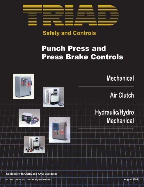
<strong>Punch</strong> <strong>Press</strong> <strong>Controls</strong>Safety <strong>and</strong> <strong>Controls</strong>Part Revolution Air Clutch/<strong>Brake</strong> <strong>Controls</strong>Complies with current OSHA St<strong>and</strong>ard 1910.217 of the Federal Register <strong>and</strong> ANSI St<strong>and</strong>ard B11.1-1988.Board Only Clutch/<strong>Brake</strong> SystemPart #SSM-05The Board Only Clutch/<strong>Brake</strong> Module (Part #SSM-05). The diverse redundantclutch/brake punch press control module with a quickview (remote panel mount)message display (available in English or Spanish). Please see the in-depthdesign criteria <strong>and</strong> system description writing available on preceding page (F1).Part #SSM-05 includes:Panel MountMessage Display• Master Board• Slave Board• Power Supply Board• Quickview Diagnostic MessageDisplay• Connecting Cables• Cover/Hardware• Software (Master) microprocessor• Software (Slave) microprocessorShort StackPart #SSM-10The Short Stack Module (Part #SSM-10) is Small in Size -- Big in Safety <strong>and</strong>Control. The diverse redundant clutch/brake punch press control module with aquickview (remote panel mount) message display (available in English or Spanish).Please see the in-depth design criteria <strong>and</strong> system description writing available onpreceding page (F1).Part #SSM-10 includes:F-2Panel MountMessage DisplayExcellent for theRebuilder or O.E.M.• Control reliable diverse redundantcontrol module• Quickview Diagnostic MessageDisplay• Fused transformer• Control module pre-wired toterminal strip• <strong>Press</strong>ure clamp terminal strip• Mounted on a 17" (432mm) x 18"(457mm) backplate• Wiring diagram <strong>and</strong> completeinstallation instructions supplied• Modes of operationoff – inch – single – continuous• Continuous ARM• Top stop• Anti-tie down <strong>and</strong> anti-repeat• System start/stop functions• SPM Range - 1 to 500• Control reliable design• Interrupted stroke provision withindicator• <strong>Inc</strong>h mode monitoring• Control module provides anti-tiedown <strong>and</strong> concurrency function forup to four sets of operator stations• Light curtain mute-out on upstrokest<strong>and</strong>ard• Clutch/brake module designed to fitinto tight spaces. Printed circuitboard dimensions; only 6.5"(165mm) x 5" (127mm) x 4"(102mm) including st<strong>and</strong>off.• Control systems are captivelydesigned, manufactured, <strong>and</strong>supported by <strong>Triad</strong> <strong>Controls</strong>.• Self-contained plain Englishmessage display• Self-diagnostic system• The control module monitors thesignals <strong>and</strong> circuits as specified byOSHA <strong>and</strong> ANSI st<strong>and</strong>ards• Control incorporates dual logicpower supplies• Two-year warranty on controlmodule
<strong>Punch</strong> <strong>Press</strong> <strong>Controls</strong>Safety <strong>and</strong> <strong>Controls</strong>Part Revolution Air Clutch/<strong>Brake</strong> <strong>Controls</strong>(continued)The Short Stack Plus (Part #SSM-20) encompasses all of the features <strong>and</strong>components of Part #SSM-10 plus all of the following switches, legend plates, pushbuttons, <strong>and</strong> indicator lights for easy mounting into your existing control panel.Short Stack PlusPart #SSM-20Part #SSM-20 includes:Keyed selector switches <strong>and</strong> legendplates for:• H<strong>and</strong>/foot mode• Off/inch/single/continuousPush buttons <strong>and</strong> legend plates for:• System start• System stop• Automatic continuous set-upIndicators <strong>and</strong> legend plates for:• System on• Ground fault• <strong>Brake</strong> monitor• Interrupted stroke provisionThe Model 3200 SS (Solid State) Control System is completely prewired <strong>and</strong>ready for installation. System supplied complete with a well marked terminal stripfor easy, safe, <strong>and</strong> accurate electrical interface to the various punch presscomponents. Due to the hybrid design characteristics of the 3200 SS, a mainpower disconnect switch <strong>and</strong> magnetic motor starters can be supplied in the samecontrol panel.Customer to specify operator control location (photo displays operator controls onpanel door).Page F-8 provides a step by step format for designing the control exactly how youwant it.• NEMA 12 EnclosureModel 3200 SS Control System• System Start Guarded Push Button (Air<strong>and</strong> Power Interlock)• System Stop Unguarded Push Button• System On Indicator Light• Message Display Plain Englishmessages for status <strong>and</strong> system selfdiagnostics• Interrupted Stroke Provision withIndicator Described on page F1.• Automatic Continuous Set Up PushButton This prior action push buttonmust be operated to set-up the press forcontinuous operation. Once depressed,the operator has a preset length of time inwhich to depress both palm buttonsconcurrently to initiate operation in thecontinuous mode.• <strong>Brake</strong> Monitor--Top Stop Indicator Oil tightlight to detect top stop overrun <strong>and</strong> is tiedinto the rotary cam to give an electromechanicalbrake monitoring system. Timebasedbrake monitoring optional.• Ground Fault Detector Oil tight push to testtype wired to continuously monitor pressgrounding whenever control power is on.• Continuous Arm Timer Fused Secondary<strong>Press</strong>ure Clamp Terminals• H<strong>and</strong>/Foot Mode Two position keyedselector for h<strong>and</strong> or foot mode initiation.• Transformer To reduce voltage from 480/240VAC to 120VAC secondary. Consultfactory for 208 or 550 volt system.Left End “LE”Panel Door “PD”Right End “RE”• Keyed Mode Selector Off-<strong>Inc</strong>h-Single-Continuous Four positionkeyed lock selector switch forsupervised selection of mode ofoperation of the press. When in theinch mode, the operator cannot holdor tie one run button down <strong>and</strong> usethe other button to inch the presswith one h<strong>and</strong> operation. Bothbuttons must be depressedconcurrently. Micro-<strong>Inc</strong>hing <strong>and</strong>Automatic External Trip optional.• LED Diagnostics <strong>Punch</strong> presscomponents <strong>and</strong> system diagnosticswith LED Indicator Lights are onprinted circuit boards for all inputs<strong>and</strong> outputs.F-3
<strong>Punch</strong> <strong>Press</strong> <strong>Controls</strong>Safety <strong>and</strong> <strong>Controls</strong>Part Revolution Air Clutch/<strong>Brake</strong> <strong>Controls</strong>(continued)Control Package 1500 SS<strong>Inc</strong>orporates all the requirements of OSHA for control reliability <strong>and</strong> componentmonitoring. Also includes component <strong>and</strong> system diagnostics with indicator lightsfor total press monitoring. Complies with section 1910.217 of the Federal Register.When foot actuation is used, a method of guarding the point of operation must beprovided. Several methods are available in this catalog.Refer to pages A-1 through A-31.Control Package 1500 SS includes the following:Model 3200 SS (Solid State) ControlSystem with componentsDual Solenoid ValveNo. 303 The L-G monitorcontains a pressurecontrolled spool in anassembly mounted betweenthe pilot <strong>and</strong> valve bodyassemblies. <strong>Press</strong>ure signalsare applied to each end ofthe monitor spool. If thesesignals differ by more than a built-in designlimit, they cause the spool to shift to a latchedposition. The spool movement causes thepilots to be exhausted <strong>and</strong> pilot supply air to bevented to the atmosphere, thus rendering thevalve inoperable. The monitor must be reset byunlatching the spool before another valve cyclecan be initiated.Rotary Cam Switch withDrive CheckNo. 310A This NEMA 1rotary switch provideslimit switch functionsrequired by controlsystem. Spring-loadedmounting absorbs shock<strong>and</strong> will stop the press should the drive chainbreak. Cams are easily adjusted with toolprovided.Heavy Duty <strong>Press</strong>ure switchNo. 306 This NEMA 12 oil-tight<strong>and</strong> dust-tight switch isadjustable from 1 to 115 PSI.OperatorStationNo. UL-501TwoUltraTouchmodulesmounted on a NEMA 12 operator station runbar with a red mushroom emergency stopbutton located in the center <strong>and</strong> a yellowmushroom top stop button located off center.This style assembly is ideal for the metalstamping/metal fabrication industry. All themodules are mounted in accordance toOSHA, ANSI, <strong>and</strong> CSA st<strong>and</strong>ards in regardsto run button spacing.Filter RegulatorLubricatorNo. 311Features- Model 3200 SS Control Panel- Exp<strong>and</strong>able- <strong>Brake</strong> Monitor- Two H<strong>and</strong> Anti-Tie Down- System Control Reliability- Single Stroke- Self-diagnostic system- Self-contained message display forsystem status & diagnostics- Non-Resumption of interrupted stroke- Provisions for Auxiliary Equipment- PSDI Presence Sensing Device Initiation(see below)Two-Year WarrantyF-4
<strong>Punch</strong> <strong>Press</strong> <strong>Controls</strong>Safety <strong>and</strong> <strong>Controls</strong>Part Revolution Air Clutch/<strong>Brake</strong> <strong>Controls</strong>(continued)The Ultimate is the most feature intensive air clutch punchpress control available. The control conforms to all currentOSHA <strong>and</strong> ANSI st<strong>and</strong>ards for control reliability <strong>and</strong>component monitoring. The system incorporates the <strong>Triad</strong><strong>Press</strong>Cam 8 for complete punch press synchronization <strong>and</strong>flexibility for all peripheral punch press signaling needs suchas feeds, die protection, lubrication, blowoffs, etc. All of theelectrical timing adjustments for the complete press operationare done at the floor level by the operator. The <strong>Press</strong>Cam 8system also has a large job memory of 75. This gives thecontrol the ability to remember 75 complete different jobs ordie set-ups at the press. The memory concept at the press isan excellent feature due to the tremendous time saved duringsetups of various operations. Additional time is saved bybeing able to adjust or “fine tune” the stamping process whilethe press is running, which is an aid in maximizing pressutilization. Detailed isolated product information on both the<strong>Press</strong>Cam 8 <strong>and</strong> the 3200 SS control system can be seen onthe preceding pages of this catalog.The UltimateModel 3200 SS with <strong>Press</strong>Cam 8 Built-inSt<strong>and</strong>ard Features• Control Panel 3200 (page F3) conforms to all currentOSHA <strong>and</strong> ANSI st<strong>and</strong>ards.• Eleven cam programmable limit switch.• Dual redundant outputs for all faults such as brakemonitor, motion detector, etc.• Built-in motion detector with fast response <strong>and</strong> dual speedlimits.• <strong>Brake</strong> Monitor - Time-based brake monitor with a digitaldisplay of both the brake stopping time <strong>and</strong> the brake faultlimit setpoints in milliseconds. System also displays abrake fault when stopping times are exceeded.• Refer to Pages E-8 through E-17 for specifics on the<strong>Press</strong>Cam 8.• Built-in tachometer (SPM) <strong>and</strong> crank shaft angle indegrees with simultaneous digital display.• Four built-in counters: stroke, batch, quality, <strong>and</strong> part.• Built-in timers, adjustable from 1 ms to 10 seconds.• Sixteen station die protection system (self-contained cyclicfunctions <strong>and</strong> two static functions) built-in with separatetiming windows for each station based on the absoluteposition of the crankshaft. All the die protection timingwindows are retained in the memory until the next time aparticular die is set-up <strong>and</strong> run. Die protection timingwindows can also be adjusted while the press is inmotion.• All the functions of the system that are timed or signalledthrough the <strong>Press</strong>Cam 8 system can be retained inmemory for 75 different die set-ups.• All the operator timing adjustments are done at the floorlevel which eliminates the need for electricians to adjustrotary cam switches <strong>and</strong> microswitches.• System self-diagnostics.• Program security from tampering:1. Keyed selector switch for supervisory control2. Authorized code for program entry• Accuracy ± 1° for all timing circuits <strong>and</strong> can be “finetuned” while the press is cycling.• Eases the timing of all types of feeding equipment, AC<strong>and</strong> DC servo feeds, <strong>and</strong> air feeds.• Very easy to program <strong>and</strong> use.• System designed specifically for the metal stamping/metal forming industry.• Main power disconnect <strong>and</strong> magnetic motor starters canbe housed in the same control panel.• Tonnage monitoring optional.F-5
<strong>Punch</strong> <strong>Press</strong> <strong>Controls</strong>Safety <strong>and</strong> <strong>Controls</strong>Part Revolution Air Clutch/<strong>Brake</strong> <strong>Controls</strong>(continued)Model 3200 RL Control SystemThe Model 3200 RL (Relay Logic) Control System is completely prewired <strong>and</strong>ready for installation <strong>and</strong> complies with current OSHA St<strong>and</strong>ard 1910.217 ofthe Federal Register <strong>and</strong> ANSI St<strong>and</strong>ard B11.1-1988. System comescomplete with a well marked terminal strip for easy, safe, <strong>and</strong> accurateelectrical interface to the various punch press components. The control panelcan also be supplied with a main power disconnect switch <strong>and</strong> magneticmotor starters mounted in the same control panel.Features of the Model 3200 RL Control System include:• Ground Fault Detector Oil tight push to test indicator is wired tocontinuously monitor press grounding whenever control power is on.• System Start Guarded Push Button (Air <strong>and</strong> Power Interlock)• System Stop Unguarded Push Button• System On Indicator Light• Automatic Continuous Set Up Push Button This prior action push buttonmust be operated to set-up the press for continuous operation. Oncedepressed, the operator has a preset length of time in which to depressboth palm buttons concurrently to initiate operation in the continuous mode.• NEMA 12 Enclosure• <strong>Brake</strong> Monitor Top Stop Indicator Oil tight light to detect top stop overrun<strong>and</strong> is tied into the rotary cam to give an electromechanical brakemonitoring system.• H<strong>and</strong>/Foot Mode Two position keyed selector for h<strong>and</strong> or foot modeinitiation.• Keyed Mode Selector Off-<strong>Inc</strong>h-Single-Continuous Four position keyed lockselector switch for supervised selection of mode of operation of the press.When in the inch mode, the operator cannot hold or tie one run button down<strong>and</strong> use the other button to inch the press with one h<strong>and</strong> operation. Bothbuttons must be depressed concurrently. Micro-<strong>Inc</strong>hing optional.• Transformer To reduce voltage from 480/240VAC to 120VAC secondary.Consult factory for 208 or 550VAC.• Continuous Arm Timer Fused Secondary <strong>Press</strong>ure Clamp Terminals• Heavy Duty Relay Logic Circuit with special contact construction for selfcheckingcircuits.F-6
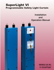
Safety <strong>and</strong> <strong>Controls</strong>Mute-Out Packagesfor <strong>Punch</strong> <strong>Press</strong> & <strong>Press</strong> <strong>Brake</strong> Control Systems<strong>Triad</strong> Mute-Out Package #130Operational Description - Package #130The Mute-Out Package #130 has been designed to allow theSuperLight VI or VII infrared light curtain to be muted out or bypassedduring the non-hazardous portion of the machine cycle.The mute-out function is actuated by the No. 301 limit switch<strong>and</strong> the No. 300 adjustable calibrated switch actuator when thedie is within 1/4" (6.35mm) of the pinch point <strong>and</strong> continuesuntil the ram returns to top stop. At this point the infrared lightcurtain reactivates <strong>and</strong> gives protection during the hazardousportion of the downstroke.<strong>Punch</strong> <strong>Press</strong>es - Reference Package #130 PPPackage #130PP enhances productivity on punch pressesbecause parts can be loaded or unloaded during the nonhazardous upstroke or to be used when parts are ejectedthrough the light curtain on the upstroke. Always submitmachine electrical schematics to assure proper point ofinterface. Specify air clutch or hydraulic machine application.<strong>Press</strong> <strong>Brake</strong>s - Reference Package #130 PBPackage #130PB interfaces directly on air clutch <strong>and</strong> hydraulicpress brakes when these machines have control reliability <strong>and</strong>component monitoring. The mute out function is activated bythe calibrated switch actuator No. 300 <strong>and</strong> gives the operatorthe capability to work with small parts <strong>and</strong> workpieces thathave flanges. Always submit machine electrical schematics toassure proper point of interface. Specify air clutch or hydraulicmachine application. Add suffix AC for air clutch press brake orsuffix HV for hydraulic press brake.Select-O-Stop (Option for Package #130PB)Select-O-Stop is an option for Package #130PB. Select-O-Stop is a keyed function (on/off) that is activated by thecalibrated switch actuator mounted on the side of the ram.Select-O-Stop will allow the operator to bring the ram down ata fast speed to a preset position which is 1/4" (6.35mm) abovethe material to be formed. At this point the ram will stop <strong>and</strong>then the light curtain mute out will begin. The Select-O-Stopfunction is ideal for small part forming or realignment of thework piece. Add suffix SOS to Package #130PB for thisfeature.G-1
<strong>Press</strong> <strong>Brake</strong> <strong>Controls</strong>Safety <strong>and</strong> <strong>Controls</strong>Safety <strong>and</strong> <strong>Controls</strong><strong>Triad</strong> SuperLight VI <strong>and</strong> VIIInfrared Light Curtainsnow designed forPower <strong>Press</strong> <strong>Brake</strong>s,Utilizing the Floating Blank seriesHow the Floating Blank Works:The <strong>Triad</strong> Floating Blank light curtain provides the flexibilitynecessary to effectively guard all types of power pressbrakes. The Floating Blank permits work pieces to be formedvertically or horizontally through the guarded area withoutshutting the machine down. Entry into the protected area bythe operator or passerby will prevent the start or, if themachine is in motion, will provide a signal to stop themachine.While other safety devices must be altered to allow materialsto be fed through, the Floating Blank is controlled by a keyedselector switch that will allow a work opening of 8 cm basedon 2 cm increments. Blanking adjustments required when dieheights change are not necessary. The Floating Blankautomatically adjusts to the various feed positions providingproduction with protection. The Floating Blank light curtainadapts to mechanical, air clutch, <strong>and</strong> hydraulic press brakes.Refer to Pages H-2 through H-15 for proper press brake controls.Refer to pages A-14 through A-31 for complete SuperLight VI <strong>and</strong> VII specifications.H-1
Safety <strong>and</strong> <strong>Controls</strong> Safety <strong>and</strong> <strong>Controls</strong><strong>Press</strong> <strong>Brake</strong> <strong>Controls</strong><strong>Press</strong> <strong>Brake</strong> Guarding <strong>and</strong> <strong>Controls</strong>Guideline to Proper Equipment SelectionIntroduction - Due to the interaction required between the operator, workpiece, <strong>and</strong> the point of operation, press brakeguarding requires versatility with both the press brake control system along with flexibility in the point of operation guardingdevice. Production can be had with the protection only when the guards <strong>and</strong> controls put on a machine are properly designedto match the operational procedures your shop may dictate; may it be a short run multiple die change job shop to the needsof a high volume long run production shop. The following packages incorporate features <strong>and</strong> functions to address the manyneeds of the industry based on our many years of experience in the metal stamping <strong>and</strong> metal forming industries.OSHA & ANSI St<strong>and</strong>ards:OSHA (Occupational Safety & Health Act) - Federal Register Sub-Part O, 1910.212.ANSI - American National St<strong>and</strong>ard B11.1-1990.<strong>Press</strong> <strong>Brake</strong>ClassificationMechanicalPartial revolution clutch-mechanicalfriction-currently uses mechanicalpedal to actuate press brakeAir ClutchPartial revolution clutch-useselectric foot switch to actuate pressWith updated controlsHydraulic/Hydro MechanicalSELECT ONE<strong>Press</strong> <strong>Brake</strong> Control OptionsPackage #2100-Converts to electric foot switch<strong>and</strong> incorporates automatic slow forming. Whenoptional ram indexing modes are added, systemis excellent for the high production shop.Updates controls for control reliability <strong>and</strong>component monitoring. Refer to Pages H-3through H-4 for details.Package #1-Retains current mechanical foottreadle to retain operator feel for slow forming.Excellent for brakes working in the top end ofthe tonnage spectrum. Updates controls forcontrol reliability <strong>and</strong> component monitoring.Refer to Pages H-5 through H-6 for details.Package #2101-<strong>Inc</strong>orporates the two-h<strong>and</strong>/footmethod of press brake control. Works well forthe low volume job shop press brake. Updatesthe controls for control reliability <strong>and</strong> componentmonitoring. Refer to Pages H-7 through H-8 fordetails.Package #2110-Converts the mechanical pressbrake to electric foot switch <strong>and</strong> incorporates asingle forming speed. This package is used forpress brakes used as punch presses. Updatesthe controls to meet current OSHA st<strong>and</strong>ardsfor control reliability <strong>and</strong> component monitoring.Refer to Pages H-9 through H-10 for details.Package #2120-Updates control to meet currentOSHA st<strong>and</strong>ards for control reliability <strong>and</strong>component monitoring. Refer to Pages H-11through H-12 for details.Package #3122-Updates control to meet currentOSHA st<strong>and</strong>ards for control reliability <strong>and</strong>component monitoring. This controlincorporates the two-h<strong>and</strong>/foot method ofcontrol <strong>and</strong> guarding. Refer to Pages H-13through H-14 for details.Package #130 PB Mute-Out-When an air clutchpress brake meets current st<strong>and</strong>ards for controlreliability <strong>and</strong> component monitoring, package#130 PB interfaces directly with the existingcontrols to mute-out the infrared light guard onthe non-hazardous portion of the stroke. Referto Page G-1 for details.Package #130 PB Mute-Out-When a hydraulicpress brake meets current st<strong>and</strong>ards for controlreliability <strong>and</strong> component monitoring, package#130 PB interfaces directly with the existingcontrols to mute-out the infrared light guard onthe non-hazardous portion of the stroke. Referto Page G-1 for details.Package #4101-Gives the hydraulic press brakethe two-h<strong>and</strong>/foot method of guarding the pointof operation. Same operational description aspackages #2101 or #3122. Submit schematicfor proper point of interface.SELECT ONEPoint of OperationGuarding Options• SuperLight VI or VII FloatingBlank infrared light curtain• SuperLight VI or VII FloatingBlank infrared light curtain only.• Utilizes two h<strong>and</strong> controlsincluded in package.• SuperLight VI or VII FloatingBlank infrared light curtain.• Two H<strong>and</strong> <strong>Controls</strong>• SuperLight VI or VII FloatingBlank infrared light curtain.• Two H<strong>and</strong> <strong>Controls</strong>• Utilizes two h<strong>and</strong> controlsincluded in package.• SuperLight VI or VII FloatingBlank infrared light curtain.• SuperLight VI or VII FloatingBlank infrared light curtain.• Two H<strong>and</strong> <strong>Controls</strong>H-2
<strong>Press</strong> <strong>Brake</strong> <strong>Controls</strong>Safety <strong>and</strong> <strong>Controls</strong>Mechanical <strong>Press</strong> <strong>Brake</strong> Control with Automatic Slow FormingPackage 2100Package 2100 incorporates single stroke function withSelect-O-Stop <strong>and</strong> ram control functions. This convertsmechanically actuated press brakes to electrical foot switchactuation <strong>and</strong> gives the press brake automatic slow formingcapability. Excellent for the long run <strong>and</strong> small piece partproduction shop where uniform piece part forming isrequired. Meets current OSHA st<strong>and</strong>ards for controlreliability <strong>and</strong> component monitoring <strong>and</strong> also incorporatesbrake monitoring.Model 3400 SS (Solid State) Control SystemComponents#302#303#300#301#311Package 2100 includes the following:Model 3400 SS (Solid State) Control System• Control reliable design• Diverse redundant design concept• Quickview diagnostic message display• Interrupted stroke provision• System logic <strong>and</strong> component diagnostics• Redundant captive contact safety relays• Control incorporates cross-checking, self checking, <strong>and</strong>diverse redundancy• Control transformer (reduces voltage from 480/260 to120VAC)• Power interlock• NEMA 12 enclosure• <strong>Brake</strong> monitor top stop indicator• Ground fault indicator• Keyed selector switch for two h<strong>and</strong>/foot mode ofoperation• System on illuminated indicator light• System start guarded push button• System stop unguarded push button• Keyed selector switch for Select-O-Stop Function on/off• Control design writing (Page F-1)• <strong>Inc</strong>orporates light curtain mute-out• Light curtain interface (optional)#306#305No. UL-102 UltraTouch Modules (optional)No. 300 Calibrated Switch Actuator (Activates Select-O-Stop)No. 301 Limit Switches (four)No. 302 Guarded Foot SwitchNo. 303 Dual Solenoid Valve with MufflerNo. 305 Ram Control Cylinder AssemblyNo. 306 Heavy Duty <strong>Press</strong>ure SwitchNo. 311 Filter, Regulator, LubricatorA proper point of operation guarding device is required when using theelectric foot switch as the activating device. Refer to Pages A1 throughA-31 for details.H-3
Safety <strong>and</strong> <strong>Controls</strong><strong>Press</strong> <strong>Brake</strong> <strong>Controls</strong>Mechanical <strong>Press</strong> <strong>Brake</strong> Control with Automatic Slow FormingRam Control Cylinder Assembly–No. 305 (<strong>Press</strong> <strong>Brake</strong> Applications)The <strong>Triad</strong> Ram Control incorporates a No. 305 ram control cylinderassembly into the Model 3400 control system to provide a slow speedfeature on mechanically actuated, friction clutch press brakes. Thisallows the operator to automatically slow-form a part to prevent damageto the part <strong>and</strong> to prevent potential injury due to part "whipping up"during the forming. When equipped with the <strong>Triad</strong> Ram Control, theram advances to a predetermined position above the work with theclutch fully engaged (fast down). At this point, the ram will stop, allowingfor realignment of the part before forming. The foot switch is thenactuated a second time <strong>and</strong> the ram will advance slowly, forming thepart <strong>and</strong> then return to the top of the stroke at a high speed (fast return).The Ram Control can be adjusted to provide the best speed for thepart being formed.Automatic Ram Cycling <strong>and</strong> Indexing OptionsAuto Cycle — All systems are designed for single stroke only. AutoCycle allows the press to continue past top stop as long as the operatorhas maintained foot pedal contact <strong>and</strong> stops at the Select-O-Stopposition. AutoCycle may only be used with a light curtain, which willprevent the press from continuing past top stop, if the operator hashis/her h<strong>and</strong> in the die area when the press reaches top stroke.Excellent for the production of small parts on press brakes <strong>and</strong>workpieces with flanges.Auto Retrip — When Select-O-Stop has been turned on, the press willautomatically stop at a preset point, which is normally set just abovethe piece part to be formed. The operator then has to release the pedal<strong>and</strong> depress it to continue the forming cycle. The Auto Retrip functionwill automatically restart the press at that point, as long as the operatormaintains foot pedal contact. Excellent for large sheet forming.Auto Form — While controlling the forming speed of a piece part, itsometimes is necessary to fully engage the clutch, just prior to thebottom of the stroke, to obtain a desired radius with the die being used.Auto Form will bypass the feed cylinder at that point, allowing fullengagement of the clutch <strong>and</strong> preventing the possibility of a stall at thebottom of the stroke. Excellent for top end tonnage forming on pressbrakes.Auto Return — <strong>Press</strong> will automatically return to top of stroke afterpiece part has been formed (requires additional limit switch). Thisfeature enhances ram cycling.Select-O-Stop function is activated by the calibrated switch actuator whichis mounted on the side of the ram. Select-O-Stop allows the operator tobring the ram down to a preset position which is 1/4" (6.35mm) above thematerial being formed <strong>and</strong> will automatically stop the ram. This gives theoperator the opportunity to realign the work piece <strong>and</strong> then slow form theworkpiece if desired. Select-O-Stop is a keyed function on/off on the maincontrol panel.Light Curtain Mute-Out automatically bypasses light curtain when die hasreached piece part <strong>and</strong> point of operation hazard no longer exists. Lightcurtain is automatically reactivated when press reaches top of stroke toprevent operator from being in point of operation during the hazardousdownstroke of the press. This feature is only used when a light curtain isused as the point of operation guarding device.Ordering Procedure (Package 2100)❏ Manufacturer of <strong>Press</strong> <strong>Brake</strong> _________________ Model _______________ Serial #_________Bed Length ___________❏ Voltage ___________Cycle _________________ Phase ________________OPTIONS❏ Electro--mechanical relay system (RL) instead of solid state (SS) control. Photo on Page F-6.❏ Motor H.P. if magnetic starter desired (Main Motor) ___ Full Load Amps ___ Rev. or Non-Rev.❏ Motor H.P. if magnetic starter desired (Ram Motor) ____ Full Load Amps ___ Rev. or Non-Rev.❏ Main Power fused electrical disconnect switch --- Yes ____ No ____❏ Rotary cam, sprockets, <strong>and</strong> chain to replace two limit switchesPRODUCTION FUNCTIONS DESIRED❏ Auto Cycle is a keyed function on control panel on/off (can only be used with a light curtain)❏ Auto Retrip is a keyed function on control panel on/off❏ Auto Form is a keyed function on control panel on/off❏ Auto Return is a keyed function on control panel on/off (requires additional limit switch)❏ SuperLight VI or VII infrared light curtain model __________________ (requires light curtain interface on control panel iflight curtain is used)❏ Light Curtain Mounting Brackets❏ Model 8000 Pedestal Mounts. Refer to Page I-2 for details.❏ Model 9000 Swing Mounting Brackets. Refer to Page I-2 for details.❏ Model BM-1600 Time-Based <strong>Brake</strong> Monitor. Refer to Page D1 through D3 for details.❏ Specify any additional options desired but not shown.H-4
<strong>Press</strong> <strong>Brake</strong> <strong>Controls</strong>Safety <strong>and</strong> <strong>Controls</strong>Mechanical <strong>Press</strong> <strong>Brake</strong> GuardingRetains Mechanical Pedal to Slow Form Parts <strong>and</strong> to Retain Operator Feel for FormingPackage 1Package 1 was designed to retain the existing mechanicalfoot pedal for machine actuation in conjunction with the useof a SuperLight VI or VII Floating Blank infrared light curtainas the point of operation guard. Excellent for the long run<strong>and</strong> where versatility is needed during the forming cycle.Meets current OSHA st<strong>and</strong>ards for control reliability <strong>and</strong>component monitoring <strong>and</strong> also incorporates brakemonitoring.Model 3400 SS (Solid State) Control SystemComponents#304#306#300#303#311#301Package 1 includes the following:Model 3400 SS (Solid State) Control System• Control reliable design• Diverse redundant design concept• Quickview diagnostic message display• Interrupted stroke provision• System logic <strong>and</strong> component diagnostics• Redundant captive contact safety relays• Control incorporates cross-checking, self checking, <strong>and</strong>diverse redundancy• Control transformer (reduces voltage from 480/260 to120VAC)• Power interlock• NEMA 12 enclosure• <strong>Brake</strong> monitor top stop indicator• Ground fault indicator• System on illuminated indicator light• System start guarded push button• System stop unguarded push button• Keyed selector switch for Select-O-Stop Function on/off• Control design writing (Page F-1)• <strong>Inc</strong>orporates light curtain mute-out• Light curtain interfaceNo. 300 Calibrated Switch Actuator (Activates Select-O-Stop)No. 301 Limit Switches (five)No. 303 Dual Solenoid Valve with MufflerNo. 304 Air Cylinder AssemblyNo. 306 Heavy Duty <strong>Press</strong>ure SwitchNo. 311 Filter, Regulator, LubricatorA proper point of operation guarding device is required when using themechanical foot pedal as the press brake actuating device. Refer to PagesA1 through A31 for proper guarding device specifications.H-5
Safety <strong>and</strong> <strong>Controls</strong><strong>Press</strong> <strong>Brake</strong> <strong>Controls</strong>Mechanical <strong>Press</strong> <strong>Brake</strong> GuardingRetains Mechanical Pedal to Slow Form Parts <strong>and</strong> to Retain Operator Feel for FormingPackage 1 allows an operator to engage <strong>and</strong> disengage themechanical friction clutch on a mechanical press brake withthe existing mechanical pedal. The light curtain is activatedat the top of the stroke (Top Stop) when the operatordepresses the mechanical foot treadle <strong>and</strong> the ram begins itsdownward travel. This is the hazardous portion of the stroke.The light curtain stays on <strong>and</strong> the machine cycles until thelight curtain is interrupted by the operator or passerby. Wheninterrupted, the solenoid valve is de-energized <strong>and</strong> the air isdumped from the air cylinder causing the press brake to stop<strong>and</strong> the mechanical foot pedal to fall to the floor. When theinterruption is cleared, the SuperLight VI or VII light curtainautomatically resets <strong>and</strong> the foot pedal gently rises tocontinue the machine cycle. The operator has total controlon the machine cycling speed <strong>and</strong> the forming speed,(slow-forming) as they currently do by retaining themechanical pedal as the actuating device.This system is excellent for the press brake that is working atthe top end of the tonnage spectrum <strong>and</strong> that works with awide range of products <strong>and</strong> where the operator must havecontrol of the forming speed.Select-O-Stop function is activated by the calibrated switchactuator which is mounted on the side of the ram. Select-O-Stop allows the operator to bring the ram down to a presetposition which is 1/4" (6.35mm) above the material beingformed <strong>and</strong> will automatically stop the ram. This gives theoperator the opportunity to realign the work piece <strong>and</strong> thenslow form the workpiece if desired. Select-O-Stop is a keyedfunction on/off on the main control panel.Automatic Ram Cycling(Package 1 is designed for single stroke only)Auto Cycle allows the press to continue past top stop aslong as the operator has maintained foot pedal contact <strong>and</strong>stop at the Select-O-Stop position. Auto Cycle may only beused with a light curtain, which will prevent the press fromcontinuing past top stop, if the operator has his/her h<strong>and</strong> inthe die area when the press reaches top of stroke. Auto-Cycle is controlled by a keyed selector switch on the controlpanel, on/off. Excellent for small part production <strong>and</strong>workpieces with flanges.Light Curtain Mute-Out Automatically bypasses light curtainwhen die has reached piece part <strong>and</strong> point of operationhazard no longer exists. Light curtain is automaticallyreactivated when press reaches top of stroke to preventoperator from being in point of operation during the hazardousdown stroke of the press. Light curtain mute-out is onlysupplied when a light curtain is used as the point of operationguarding device.Package 1 Ordering Procedure• Manufacturer of <strong>Press</strong> <strong>Brake</strong> ___________________ Model __________ Serial #___________Bed Length ______________• Voltage ___________Cycle _________________ Phase ________________OPTIONS• Electro--mechanical relay system (RL) instead of solid state (SS) control. Photo on Page F-6.• SuperLight VI or VII Floating Blank infrared light curtain model. Refer to Pages A21 through A31 for selecting model(requires light curtain interface on control panel when light curtain is used).• Light curtain Mounting Bracket• Model 8000 Pedestal Mounts. Refer to Page I-2 for details.• Model 9000 Swing Mounting Brackets. Refer to Page I-2 for details.• Motor H.P. if magnetic starter desired (Main Motor) ___ Full Load Amps ___ Rev. or Non-Rev.• Motor H.P. if magnetic starter desired (Ram Motor) ____ Full Load Amps ___ Rev. or Non-Rev.• Main Power fused electrical disconnect switch --- Yes ____ No ____• Rotary cam, sprockets, <strong>and</strong> chain to replace two limit switches• Model BM-1600 Time Based <strong>Brake</strong> Monitor. Refer to Pages D-1 through D-3 for specifications.• Auto Cycle is a keyed function on the control panel on/off (can only be used with a light curtain)• Specify any additional options desired but not shownH-6
<strong>Press</strong> <strong>Brake</strong> <strong>Controls</strong>Safety <strong>and</strong> <strong>Controls</strong>Mechanical <strong>Press</strong> <strong>Brake</strong> GuardingTwo-H<strong>and</strong>/Foot Method of Guarding <strong>and</strong> Machine ControlPackage 2101Package 2101 is for converting mechanical press brakescurrently being actuated by a mechanical treadle.This system provides a two-h<strong>and</strong>/foot method of guarding<strong>and</strong> machine control which converts the press to electric footpedal operation. System has single stroke <strong>and</strong> is footactuated with Select-O-Stop <strong>and</strong> automatic ram control.Excellent for the job shop for the versatility needed in shortruns.Meets current OSHA st<strong>and</strong>ards for control reliability <strong>and</strong>component monitoring <strong>and</strong> also incorporates brakemonitoring.Model 3400 SS (Solid State) Control SystemComponents#302#303#300#301#311Package 2101 includes the following:Model 3400 SS (Solid State) Control System• Control reliable design• Diverse redundant design concept• Quickview diagnostic message display• Interrupted stroke provision• System logic <strong>and</strong> component diagnostics• Redundant captive contact safety relays• Control incorporates cross-checking, self checking, <strong>and</strong>diverse redundancy• Control transformer (reduces voltage from 480/260 to120VAC)• Power interlock• NEMA 12 enclosure• <strong>Brake</strong> monitor top stop indicator• Ground fault indicator• Keyed selector switch for two h<strong>and</strong>/foot method ofguarding <strong>and</strong> machine control (optional)• System on illuminated indicator light• System start guarded push button• System stop unguarded push button• Keyed selector switch for Select-O-Stop Function on/off• Control design writing (Page F-1)#306#305UL-102No. UL-102 UltraTouch Modules (two)No. 300 Calibrated Switch Actuator (Activates Select-O-Stop)No. 301 Limit Switches (four)No. 302 Guarded Foot SwitchNo. 303 Dual Solenoid Valve with MufflerNo. 305 Ram Control Cylinder AssemblyNo. 306 Heavy Duty <strong>Press</strong>ure SwitchNo. 311 Filter, Regulator, LubricatorH-7
<strong>Press</strong> <strong>Brake</strong> <strong>Controls</strong>Safety <strong>and</strong> <strong>Controls</strong>Mechanical <strong>Press</strong> <strong>Brake</strong> GuardingTwo-H<strong>and</strong>/Foot Method of Guarding <strong>and</strong> Machine ControlTwo-H<strong>and</strong>, Foot ControlThe two-h<strong>and</strong>/foot method of guarding <strong>and</strong> machine control of press brakeoperation is unique in that it provides point of operation guarding, yetallows operator to form the part without interference from a guard. Unlikesome systems, no additional setup time is required.When the press stops at the top of the stroke, the foot switch isautomatically deactivated, requiring the operator to use the palm buttonsonce again to bring the ram down to its preset position.If the operator does not need to hold the part at any time during the stroke,the keyed selector switch may be turned to "h<strong>and</strong> only." Use of the h<strong>and</strong>buttons only enables the operator to cycle the press through one completestroke without stopping. Similar to punch press work.The press may be jogged at any time but will stop when either the palmbuttons or foot pedal is released.Many safety devices are bypassed for setup purposes. However, thissystem is ideal for setup since the operator must use the two-h<strong>and</strong>/footmethod for setup as well as production. At the same time, it will not createany additional problems during set up.Operational Description• Operator depresses the two run buttons <strong>and</strong> initiates the press brakestroke.• Operator must hold the buttons down <strong>and</strong> the ram descends at fastspeed down to the 1/4" (6.35mm) position above the workpiece. If theoperator releases one or both run buttons, the ram will stopautomatically. If the control panel is keyed to "h<strong>and</strong> only," the ram willmake one complete stroke. This is helpful if the press brake is usedfor punching, piercing, notching, or blanking.• Select-O-Stop automatically stops ram 1/4" (6.35mm) above theworkpiece.• If the workpiece is not already in die, it may be inserted at this time.• The two-h<strong>and</strong> control or the foot switch is now re-initiated <strong>and</strong> thepress brake slow forms the workpiece <strong>and</strong> then returns to top stop athigh speed. The press brake is then ready for the next stroke.Ram Control Cylinder Assembly–No. 305 (<strong>Press</strong> <strong>Brake</strong>Applications) The <strong>Triad</strong> Ram Control incorporates a No. 305 ramcontrol cylinder assembly into the Model 3400 control system toprovide a slow speed feature on mechanically actuated, frictionclutch press brakes. This allows the operator to automatically slowforma part to prevent damage to the part <strong>and</strong> to prevent potentialinjury due to part "whipping up" during the forming. When equippedwith the <strong>Triad</strong> Ram Control, the ram advances to a predeterminedposition above the work with the clutch fully engaged (fast down).At this point, the ram will stop, allowing for realignment of the partbefore forming. The foot switch is then actuated a second time<strong>and</strong> the ram will advance slowly, forming the part <strong>and</strong> then returnto the top of the stroke at a high speed (fast return). The RamControl can be adjusted to provide the best speed for the partbeing formed.Select-O-Stop is a keyed function that is activated by the calibratedswitch actuator which is mounted on the side of the ram. Select-O-Stop allows the operator to bring the ram down in fast speed toa preset position which is 1/4" (6.35mm) above the material beingformed <strong>and</strong> will automatically stop the ram. This gives the operatorthe opportunity to realign the work piece <strong>and</strong> then slow form theworkpiece if desired. Select-O-Stop is a keyed function on/off onmain control panel.Package 2101 Ordering Procedure• Manufacturer of <strong>Press</strong> <strong>Brake</strong> __________________ Model ____________ Serial #_______________• Voltage ___________Cycle _________________ Phase ________________OPTIONS:• Electro--mechanical relay system (RL) instead of solid state (SS) control. Photo on Page F-6.• Motor H.P. if magnetic starter desired (Main Motor) ___ Full Load Amps ___ Rev. or Non-Rev.• Motor H.P. if magnetic starter desired (Ram Motor) ____ Full Load Amps ___ Rev. or Non-Rev.• Main Power fused electrical disconnect switch --- Yes ____ No ____• Rotary cam, sprockets, <strong>and</strong> chain to replace two limit switches• Model BM-1600 Time-Based <strong>Brake</strong> Monitor. Refer to Pages D1 through D3 for specifications.• Model 8500 pedestal mount for operator run buttons. Specify height from floor. Refer to Page I-2 for specifications.• Additional run buttons for multiple press operators, keyed switch controlled• Auto-Return function is a keyed function on control panel on/off (requires additional limit switch)• Specify any additional options desired but not shownH-8
<strong>Press</strong> <strong>Brake</strong> <strong>Controls</strong>Safety <strong>and</strong> <strong>Controls</strong>Mechanical <strong>Press</strong> <strong>Brake</strong> Control When Used as <strong>Punch</strong> <strong>Press</strong>Package 2110Package 2110 Control converts mechanically actuated pressbrakes to electrical foot switch operation <strong>and</strong> gives the pressbrake single forming speed when used as a mechanicalpower press for punching, piercing, notching, or blankingoperations. The control incorporates single stroke functionwith Select-O-Stop <strong>and</strong> utilizes an electric foot switch formachine actuation. Meets OSHA st<strong>and</strong>ards for controlreliability <strong>and</strong> component monitoring <strong>and</strong> also incorporatesbrake monitoring.Model 3400 SS (Solid State) Control SystemComponents#302#303#300#301#311Package 2110 includes the following:Model 3400 SS (Solid State) Control System• Control reliable design• Diverse redundant design concept• Quickview diagnostic message display• Interrupted stroke provision• System logic <strong>and</strong> component diagnostics• Redundant captive contact safety relays• Control incorporates cross-checking, self checking, <strong>and</strong>diverse redundancy• Control transformer (reduces voltage from 480/260 to120VAC)• Power interlock• NEMA 12 enclosure• <strong>Brake</strong> monitor top stop indicator• Ground fault indicator• Keyed selector switch for two h<strong>and</strong>/foot method ofguarding <strong>and</strong> machine control• System on illuminated indicator light• System start guarded push button• System stop unguarded push button• Keyed selector switch for Select-O-Stop Function on/off• Control design writing (Page F-1)• <strong>Inc</strong>orporates light curtain mute-out• Light curtain interface (optional)#306#304No. UL-102 UltraTouch Modules (optional)No. 300 Calibrated Switch Actuator (Activates Select-O-Stop)No. 301 Limit Switches (four)No. 302 Guarded Foot SwitchNo. 303 Dual Solenoid Valve with MufflerNo. 304 Air Cylinder AssemblyNo. 306 Heavy Duty <strong>Press</strong>ure SwitchNo. 311 Filter, Regulator, LubricatorA proper point of operation guarding device is required when using theelectric foot switch as the activating device. Refer to SuperLight VI or VIIProgrammable Safety Light Curtain for proper guarding devicespecifications.H-9
<strong>Press</strong> <strong>Brake</strong> <strong>Controls</strong>Safety <strong>and</strong> <strong>Controls</strong>Mechanical <strong>Press</strong> <strong>Brake</strong> Control When Used as <strong>Punch</strong> <strong>Press</strong>Operational DescriptionPackage 2110 allows the press brake to be operated as apartial revolution punch press. The controls meet all currentst<strong>and</strong>ards for control reliability <strong>and</strong> component monitoring<strong>and</strong> also incorporates brake monitoring. The normaloperating procedure is the same as a partial revolutionpunch press.• Operator inserts workpiece into the die area• Operator clears body parts from hazardous zone• Operator initiates the ram cycle• Ram cycles <strong>and</strong> stops at top stop• Operator then removes workpiece from die areaAutomatic Ram Cycling <strong>and</strong> Indexing OptionsAuto Cycle — All systems are designed for single strokeonly. Auto Cycle allows the press to continue past top stopas long as the operator has maintained foot pedal contact<strong>and</strong> stops at the Select-O-Stop position. Auto-Cycle mayonly be used with a light curtain, which will prevent thepress from continuing past top stop, if the operator hashis/her h<strong>and</strong> in the die area when the press reaches topstroke. Excellent for the production of small parts <strong>and</strong>workpieces with flanges.Auto Return — <strong>Press</strong> will automatically return to top ofstroke after piece part has been formed (requires additionallimit switch). This feature enhances ram cycling.Select-O-Stop function is activated by the calibrated switchactuator which is mounted on the side of the ram. Select-O-Stop allows the operator to bring the ram down to apreset position which is 1/4" (6.35mm) above the materialbeing formed <strong>and</strong> will automatically stop the ram. Thisgives the operator the opportunity to realign the work piece<strong>and</strong> then slow form the workpiece if desired. Select-O-Stop is a keyed function on/off on the main control panel.Light Curtain Mute-Out Automatically bypasses lightcurtain when die has reached piece part <strong>and</strong> point ofoperation hazard no longer exists. Light curtain isautomatically reactivated when press reaches top of stroketo prevent operator from being in point of operation duringthe hazardous downstroke of the press. This feature isonly used when the SuperLight VI or VII infrared light curtainis used as the point of operation guarding device.Package 2110 Ordering Procedure• Manufacturer of <strong>Press</strong> <strong>Brake</strong> _____________ Model ____________ Serial #__________ Bed Length ____________• Voltage ___________Cycle _________________ Phase ________________OPTIONS• Electro--mechanical relay system (RL) instead of solid state (SS) control. Photo on Page F-6.• Main Power fused electrical disconnect switch --- Yes ____ No ____• Motor H.P. if magnetic starter desired (Main Motor) ___ Full Load Amps ___ Rev. or Non-Rev.• Motor H.P. if magnetic starter desired (Ram Motor) ____ Full Load Amps ___ Rev. or Non-Rev.• Rotary cam, sprockets, <strong>and</strong> chain to replace two limit switchesPRODUCTION FUNCTIONS DESIRED• Model BM-1600 Time Based <strong>Brake</strong> Monitor. Refer to Pages D1 through D3 for specifications.• Auto cycle is a keyed function on control panel on/off (can only be used with a light curtain)• Auto return is a keyed function on control panel on/off (requires additional limit switch)• Light curtain Model. Refer to Pages A1 through A31 (requires light curtain interface on control panel if light curtain is used)• Light curtain Mounting Brackets• Model 9000 Swing Mounting Brackets. Refer to Page I-2 for specifications.• Model 8000 Pedestal Mounts. Refer to Page I-2 for specifications.• Palm button actuation; operator station UL-401. Refer to Pag C-7.• Specify any additional options desired but not shownH-10
<strong>Press</strong> <strong>Brake</strong> <strong>Controls</strong>Safety <strong>and</strong> <strong>Controls</strong>Air Clutch <strong>Press</strong> <strong>Brake</strong> <strong>Controls</strong>Updates <strong>Controls</strong> to Obtain Control ReliabilityPackage 2120Model 3400 SS (Solid State) Control SystemComponents#311#306#300#302Package 2120 updates the controls on air clutch pressbrakes to meet current OSHA st<strong>and</strong>ards for control reliability<strong>and</strong> component monitoring <strong>and</strong> also incorporates brakemonitoring.Single-stroke, foot-actuated function with Select-O-Stop.Package 2120 includes the following:Model 3400 SS (Solid State) Control System• Control reliable design• Diverse redundant design concept• Quickview diagnostic message display• Interrupted stroke provision• System logic <strong>and</strong> component diagnostics• Redundant captive contact safety relays• Control incorporates cross-checking, self checking, <strong>and</strong>diverse redundancy• Control transformer (reduces voltage from 480/260 to120VAC)• Power interlock• NEMA 12 enclosure• <strong>Brake</strong> monitor top stop indicator• Ground fault indicator• Keyed selector switch for two-h<strong>and</strong>/foot method ofguarding <strong>and</strong> machine control (optional)• System on illuminated indicator light• System start guarded push button• System stop unguarded push button• Keyed selector switch for Select-O-Stop Function on/off• Control design writing (Page F-1)• <strong>Inc</strong>orporates light curtain mute-out• Light curtain interface (optional)#303#301No. UL-102 UltraTouch Modules (optional)No. 300 Calibrated Switch Actuator (Activates Select-O-Stop)No. 301 Limit Switches (four)No. 302 Guarded Foot SwitchNo. 303 Dual Solenoid Valve with MufflerNo. 306 Heavy Duty <strong>Press</strong>ure SwitchNo. 311 Filter, Regulator, LubricatorA proper point of operation guarding device is required when using theelectric foot switch as the activating device. Refer to SuperLight VI or VIISafety Light Curtain for proper guarding device applications.H-11
Safety <strong>and</strong> <strong>Controls</strong><strong>Press</strong> <strong>Brake</strong> <strong>Controls</strong>Air Clutch <strong>Press</strong> <strong>Brake</strong> <strong>Controls</strong>Updates <strong>Controls</strong> to Obtain Control ReliabilityPackage 2120 is designed for the air clutch press brake thatrequires the controls to be updated to meet current controlreliability st<strong>and</strong>ards. The controls are designed to meet thesest<strong>and</strong>ards for forming operations <strong>and</strong> also for air clutch pressbrakes which are used for punching, piercing, or notchingoperations. SuperLight VI or VII safety light curtains can beadded to this control to obtain proper point of operationguarding. Refer to Pages A-1 through A-31.Operational Description• Operator depresses foot switch <strong>and</strong> ram descends atfast speed to Select-O-Stop position 1/4" (6.35mm)above the workpiece.• Work piece is realigned or slow-forming mode of thepress brake is actuated. At this time the point ofoperation guard is muted-out until ram returns to top stopposition.• This control is designed to retain current press brakefunctions <strong>and</strong> to incorporate control reliability <strong>and</strong>component monitoring.Select-O-Stop is a keyed function that is activated by thecalibrated switch actuator which is mounted on the side of theram. Select-O-Stop allows the operator to bring the ram downin fast speed to a preset position which is 1/4" (6.35mm) abovethe material being formed <strong>and</strong> will automatically stop the ram.This gives the operator the opportunity to realign the work piece<strong>and</strong> then slow form the workpiece if desired. Select-O-Stop isa keyed function on/off on main control panel.Automatic Ram Cycling <strong>and</strong> Indexing OptionsAuto Cycle — All systems are designed for single stroke only.Auto Cycle allows the press to continue past top stop as longas the operator has maintained foot pedal contact <strong>and</strong> stopsat the Select-O-Stop position. Auto Cycle may only be usedwith a light curtain, which will prevent the press from continuingpast top stop, if the operator has his/her h<strong>and</strong> in the die areawhen the press reaches top stroke. Excellent for the productionof small parts on press brakes <strong>and</strong> workpieces with flanges.Auto Return — <strong>Press</strong> will automatically return to top of strokeafter piece part has been formed (requires additional limitswitch). This feature enhances ram cycling.Light Curtain Mute-Out — Automatically bypasses lightcurtain when die has reached piece part <strong>and</strong> point of operationhazard no longer exists. Light curtain is automaticallyreactivated when press reaches top of stroke to preventoperator from being in point of operation during the hazardousdownstroke of the press. Light curtain mute out only is suppliedwhen a light curtain is used as the point of operation guardingdevice.Package 2120 Ordering Procedure• Manufacturer of <strong>Press</strong> <strong>Brake</strong> __________________ Model _____________________Serial #________________• Voltage ___________Cycle _________________ Phase ________________ Specify: Single Speed Twin SpeedOPTIONS• Electro--mechanical relay system (RL) instead of solid state (SS) control. Photo on Page F-6.• Motor H.P. if magnetic starter desired (Main Motor) ___ Full Load Amps ___ Rev. or Non-Rev.• Motor H.P. if magnetic starter desired (Ram Motor) ____ Full Load Amps ___ Rev. or Non-Rev.• Main Power fused electrical disconnect switch --- Yes ____ No ____• Rotary cam, sprockets, <strong>and</strong> chain to replace two limit switches• Model BM-1600 Time-Based <strong>Brake</strong> Monitor. Refer to Pages D1 through D3 for specifications.PRODUCTION FUNCTIONS DESIRED:• Auto Cycle is a keyed function on control panel on/off (can only be used with light curtain)• Auto Return is a keyed function on control panel on/off (requires additional limit switch)POINT OF OPERATION GUARD OPTIONS:• SuperLight VI or VII infrared light curtain model. Refer to Pages A21 through A31 for selecting model (requires lightcurtain interface on control panel if light curtain is used)• Light curtain mounting brackets• Model 8000 Pedestal Mounts. Refer to Page I-2 for specifications.• Model 9000 Swing Mounts. Refer to Page I-2 for specifications.H-12
<strong>Press</strong> <strong>Brake</strong> <strong>Controls</strong>Safety <strong>and</strong> <strong>Controls</strong>Air Clutch <strong>Press</strong> <strong>Brake</strong> <strong>Controls</strong>Updates <strong>Controls</strong> to Obtain Control Reliability for Two-H<strong>and</strong>/Foot Method of Guarding <strong>and</strong> Machine ControlPackage 3122Package 3122 updates the controls on air clutch pressbrakes to meet current OSHA st<strong>and</strong>ards for control reliability<strong>and</strong> component monitoring. It also incorporates the twoh<strong>and</strong>/footmethod of guarding the point of operation. Thecontrol also incorporates brake monitoring.Model 3400 SS (Solid State) Control SystemComponents#302#303#311Package 3122 includes the following:Model 3400 SS (Solid State) Control System• Control reliable design• Diverse redundant design concept• Quickview diagnostic message display• Interrupted stroke provision• System logic <strong>and</strong> component diagnostics• Redundant captive contact safety relays• Control incorporates cross-checking, self checking, <strong>and</strong>diverse redundancy• Control transformer (reduces voltage from 480/260 to120VAC)• Power interlock• NEMA 12 enclosure• <strong>Brake</strong> monitor top stop indicator• Ground fault indicator• Keyed selector switch for two-h<strong>and</strong>/foot method ofguarding <strong>and</strong> machine control (optional)• System on illuminated indicator light• System start guarded push button• System stop unguarded push button• Keyed selector switch for Select-O-Stop Function on/off• Control design writing (Page F-1)#300#301No. UL-102 UltraTouch Modules (two)No. 300 Calibrated Switch Actuator (Activates Select-O-Stop)No. 301 Limit Switches (four)No. 302 Guarded Foot SwitchNo. 303 Dual Solenoid Valve with MufflerNo. 306 Heavy Duty <strong>Press</strong>ure SwitchNo. 311 Filter, Regulator, Lubricator#306UL-102A proper point of operation guarding device is required when using theelectric foot switch as the activating device. Refer to SuperLight VI or VIISafety Light Curtain for proper guarding device applications.H-13
<strong>Press</strong> <strong>Brake</strong> <strong>Controls</strong>Safety <strong>and</strong> <strong>Controls</strong>Air Clutch <strong>Press</strong> <strong>Brake</strong> <strong>Controls</strong>Updates <strong>Controls</strong> to Obtain Control Reliability for Two H<strong>and</strong>/Foot Method of Guarding <strong>and</strong> Machine ControlTwo-H<strong>and</strong>, Foot ControlThe two-h<strong>and</strong>/foot method of press brake operation isunique in that it provides point of operation guarding, yetallows operator to form the part without interference from aguard. Unlike some systems, no additional setup time isrequired.When the press stops at the top of the stroke, the foot switchis automatically deactivated, requiring the operator to use thepalm buttons once again to bring the ram down to its presetposition.If the operator does not need to hold the part at any timeduring the stroke, the keyed selector switch may be turned to"h<strong>and</strong> only." Use of the h<strong>and</strong> buttons only enables theoperator to cycle the press through one complete strokewithout stopping. Similar to punch press work.The press may be jogged at any time but will stop wheneither the palm buttons or foot pedal is released.Many safety devices are bypassed for setup purposes.However, this system is ideal for setup since the operatormust use the two-h<strong>and</strong>/foot method for setup as well asproduction. At the same time, it will not create any additionalproblems during set up.Operational Description• Operator depresses the two run buttons <strong>and</strong> initiates thepress brake stroke.• Operator must hold the buttons down <strong>and</strong> the ramdescends at fast speed down to the 1/4" (6.35m)position above the workpiece. If the operator releasesone or both run buttons, the ram will stop automatically.If the control panel is keyed to "h<strong>and</strong> only," the ram willmake one complete stroke. This is helpful if the pressbrake is used for punching, piercing, notching, orblanking.• Select-O-Stop automatically stops ram 1/4" (6.35m)above the workpiece.• If the workpiece is not already in die, it may be insertedat this time.• The two-h<strong>and</strong>/foot method or the foot switch is now reinitiated<strong>and</strong> the press brake slow forms the workpiece<strong>and</strong> then returns to top stop at high speed. The pressbrake is then ready for the next stroke.Select-O-Stop is a keyed function that is activated by thecalibrated switch actuator which is mounted on the side ofthe ram. Select-O-Stop allows the operator to bring the ramdown in fast speed to a preset position which is 1/4" (6.35m)above the material being formed <strong>and</strong> will automatically stopthe ram. This gives the operator the opportunity to realignthe work piece <strong>and</strong> then slow form the workpiece if desired.Select-O-Stop is a keyed function on/off on main controlpanel.Automatic Ram Cycling <strong>and</strong> Indexing OptionsAuto Return — <strong>Press</strong> will automatically return to top of strokeafter piece part has been formed (requires additional limitswitch). This feature enhances ram cycling.Package 3122 Ordering Procedure• Manufacturer of <strong>Press</strong> <strong>Brake</strong> ______________ Model ___________________ Serial #____________________• Voltage ___________Cycle _________________ Phase ________________OPTIONS• Electro--mechanical relay system (RL) instead of solid state (SS) control. Photo on Page F-6.• Motor H.P. if magnetic starter desired (Main Motor) ___ Full Load Amps ___ Rev. or Non-Rev.• Motor H.P. if magnetic starter desired (Ram Motor) ____ Full Load Amps ___ Rev. or Non-Rev.• Main Power fused electrical disconnect switch --- Yes ____ No ____• Rotary cam, sprockets, <strong>and</strong> chain to replace two limit switches• Model BM-1600 Time-Based <strong>Brake</strong> Monitor Description. Refer to Pages D-1 through D-3 for specifications.• Model 8500 Pedestal mount for operator run buttons. Refer to Page I-2 for details.• Additional run buttons for multiple press operators• Auto-return function--<strong>Press</strong> will return to top of stroke after part has been formed (requires additional limit switch)• Specify any additional options desired but not shownH-14
<strong>Press</strong> <strong>Brake</strong> <strong>Controls</strong>Safety <strong>and</strong> <strong>Controls</strong><strong>Press</strong> <strong>Brake</strong> ClassificationAir Clutch, Hydraulic, Hydro-MechanicalThese designs of press brakes usually incorporate twin forming speeds <strong>and</strong> arenormally actuated by an electric foot switch. Due to their more recent date ofmanufacture, the controls normally have control reliability but verification of thisshould be done prior to machine guarding. If the controls meet current st<strong>and</strong>ards,the following is needed:• Mute-Out Package #130 PB (see Page G-1)• SuperLight VI or VII Safety Light Curtain (see Pages A-14 through A-31)• Mounting Brackets for light curtain (see below)NOTE: Always submit the machine electrical schematic to assure proper point ofinterface.Pedestal MountsPainted OSHA yellow <strong>and</strong> made of heavy angle construction.Both models are supplied with a floor mounting plate that canbe lagged to the floor.Model 8000: used to mount cornering mirrors or safety lightcurtains off of a machine.Model 8500: used to mount an operator station or palmbuttons off of a machine <strong>and</strong> includes a top plate formounting.Swing Mount BracketsModel 9000: Excellent method of mounting light curtain forpress brakes or when light curtain is to be moved for dieset-ups or machine maintenance. Model 9000 consists ofthree 180 degree pivot points along with light curtaindiagonal movement capability for virtually unlimited lightcurtain positioning. Model 9000 is a two-inch square tubingpainted OSHA yellow which mounts directly onto themachine housing making it a heavy duty yet versatilemounting bracket.B <strong>and</strong> C Dimensions are Required1. Pivot Point (1) will rotate 90 degrees in eitherdirection from position shown.2. Pivot Point (2) will rotate 180 degrees to theright from position shown.3. Pivot Point (3) will rotate 90 degrees in anydirection from position shown.4. Light curtain mounting plate is slotted to allowadjustment up or down.H-15
Safety <strong>and</strong> <strong>Controls</strong>Componentsfor <strong>Punch</strong> <strong>Press</strong> & <strong>Press</strong> <strong>Brake</strong> Control SystemsNEED PHOTOAir Cylinder AssemblyNo. 304A 1 1/2" (38mm) bore, 1" (25mm)stroke air cylinder, completemounting bracket, <strong>and</strong> clevis.Automatic Ram ControlCylinderNo. 305(<strong>Press</strong> <strong>Brake</strong> Applications)Provides a slow speed featureon mechanically actuated,friction clutch press brakesallowing the operator toautomatically slow-form a partpreventing damage <strong>and</strong> potentialinjury due to part "whipping up"during the forming. When used,the ram advances to apredetermined position abovethe work with the clutch fullyengaged (fast down). At thispoint, the ram will stop allowingfor realignment of the part beforeforming. The foot switch is thenactuated a second time <strong>and</strong> theram will advance slowly formingthe part <strong>and</strong> then return to thetop of the stroke at a high speed(fast return). The Ram Controlcan be adjusted to provide thebest speed for the part beingformed.Calibrated Switch ActuatorNo. 300Used for all press brake guardsfor actuating Select-O-Stop.Dual Solenoid ValveNo. 303A most important aspect of doublevalve design is the incorporation oftwo separate 3/2 normally closedvalve elements which areinterconnected within a common valvebody assembly. Each of the two valveelements is operated by its own 3/2normally closed solenoid pilot valve.When simultaneously energized, bothmain valve elements are operatedsimultaneously. The probability of bothvalve elements malfunctioning on thesame cycle is extremely remote.A mechanical power press or other hazardous machine using apneumatically controlled clutch <strong>and</strong> brake mechanism should usea double valve with a self-contained monitoring device <strong>and</strong>/orexternal monitoring system which inhibits further operation of thevalve <strong>and</strong> machine in the event of a failure within the valve. Ofcourse, a double valve is just one of the components in a presscontrol system <strong>and</strong> any other elements of the system should beplanned with safety as a primary consideration.Electric Foot PedalNo. 302An oil-tight foot switch. Containsone set, normally-open contacts,<strong>and</strong> one set normally-closedcontacts. <strong>Inc</strong>ludes a treadleguard to protect againstaccidental tripping. “Requires apoint of operation guard whenused for machine actuation,"such as safety light curtains orsafety interlock systems.Filter, Regulator, LubricatorNo. 311I-1
Componentsfor <strong>Punch</strong> <strong>Press</strong> & <strong>Press</strong> <strong>Brake</strong> Control SystemsSafety <strong>and</strong> <strong>Controls</strong>Heavy Duty <strong>Press</strong>ure SwitchNo. 306NEMA 12 oil-tight <strong>and</strong> dust-tightswitch is adjustable from 1 to 115PSI.Pedestal MountsPainted OSHA yellow <strong>and</strong> madeof heavy angle construction.Model 8000: used to mountcornering mirrors or safety lightcurtains off of a machine.Model 8500: used to mount anoperator station or palm buttonsoff of a machine <strong>and</strong> includes atop plate for mounting.Both models are supplied with afloor mounting plate that can belagged to the floor.Limit SwitchNo. 301Oil-tight limit switch contains oneset normally-open contacts <strong>and</strong>one set normally-closedcontacts.Miniature Regulator, Oiler,FilterNo. 311ARotary Cam Switch with DriveCheckNo. 310AThe primary components whichmake up the Rotating Cam LimitSwitch are Snap Action Switches<strong>and</strong> the Micro-Adjust Cams. TheMicro-Adjust Cam Block consistsof two cams with 180 degreelobes which can be adjustedrelative to the cam shaft bysimply rotating the adjusting disc.No tools are required to makethis adjustment. The adjustingdisc can be manually rotated asshown in the photograph. Thecam block has a self-lockingpolyurethane gear whichautomatically locks the camsrelative to the cam shaft, whenthe required contact setting hasbeen obtained.Operation StationNo. UL-501<strong>Inc</strong>ludes two run palm buttons<strong>and</strong> one emergency stop palmbutton, internally wired.Palm ButtonNo. 318<strong>Inc</strong>ludes ring guard <strong>and</strong>mounting enclosure.See ergonomic palm buttons tocontrol carpal tunnel syndrome.Swing Mount BracketsModel 9000Consists of three 180 degreepivot points along with light guarddiagonal movement capability forvirtually unlimited light guardpositioning. Two inch squaretubing painted OSHA yellowwhich mounts directly onto themachine housing making it aheavy duty yet versatile mountingbracket.UltraTouch ModuleNo. UL-102I-2
Safety <strong>and</strong> <strong>Controls</strong>Componentsfor <strong>Punch</strong> <strong>Press</strong> & <strong>Press</strong> <strong>Brake</strong> Control SystemsShut-Off ValveControl of Hazardous Energy Sources(Lockout / Tagout)Dept. of Labor Occupational Safety & Health Admin. 29CFR Part 1910TO8 Shut-Off Valves, typically attached to the inlet end of acombination unit, are manually operated, slide type valvesthat open <strong>and</strong> close with a short one-inch movement of theslide. The valve slide can be locked in the closed positionwith a customer supplied padlock. The st<strong>and</strong>ard valve is athree-way valve that exhausts downstream air in the closedposition.Ordering ProcedureThree-Way ValvesExhaust DownstreamPart Size PTFAir in Closed Position1/4” (6mm) Part #TO8-200-E1PA3/8” (10mm) Part #TO8-300-E1PA1/2” (13mm) Part #TO8-400-E1PAMaterials of ConstructionBody: ZincSlide: Acetal PlasticElastomers: NitrideDimensionsAll dimensions in inches (millimeters)Copies of the actual OSHA st<strong>and</strong>ard may be obtained from:U.S. Department of LaborOccupational Safety & Health AdministrationOffice of Public Affairs - Room N3647200 Constitution AvenueWashington, D.C. 20210(202) 693-1999International Inquires:Jacquelyn DeMesme-GrayOSHA Coordinator for International AffairsU.S. Department of LaborOccupational Safety & Health AdministrationDivision of International Affairs - Room N3641200 Constitution AvenueWashington, D.C. 20210(202) 693-2400www.osha.govI-3
<strong>Brake</strong> Performance TesterSemelex ® II Safetimeter ® Test SetSafety <strong>and</strong> <strong>Controls</strong>OSHA Uses Our Safetimeter...Shouldn't You?Our newly designed Semelex ® II Safetimeter ® Test Set isfield proven to accurately measure press stop time <strong>and</strong>safety distance to verify compliance with federal <strong>and</strong> staterequirements. Designed for harsh industrial environments,the unit is portable, light weight, easy to use, <strong>and</strong>incorporates new <strong>and</strong> improved features.Ruggedized Auto-H<strong>and</strong>Built for pressrooms, it will release a run button or push anE-Stop button to initiate press stop when signaled by theposition/velocity transducer.Redesigned Auto-FlagConnects to the Auto-H<strong>and</strong> <strong>and</strong> is positioned outside thesensing field of safety light curtains. It initiates a press stopby interrupting the sensing zone at a preset point in thestroke to check stop time.Heavy-Duty Position/Velocity TransducerIndustrial grade magnets for secure mounting to base <strong>and</strong>upper bolster. It provides accurate direction, position, <strong>and</strong>velocity signals to the meter for testing press strokes up to49 inches.Quick-Charge BatteryThe unit's built-in battery can be fully recharged in eighthours or can run off of AC power. You can not over-chargethe battery <strong>and</strong> a charge indicator signals you when thebattery is low.Two Safetimeters in OneThe same unit can be used to check full or part revolutionclutch presses.SpecificationsStop Time (Ts)Safety Distance (Ds)<strong>Press</strong> StrokeOperating:Between ChargesCharge TimeAccuracyPower SupplyOptions9.999 seconds, max999.9 inches, max49 inches, max3-5 days typical on/off8 hours+/- 1% of reading• 115VAC 50/60 Hz Supply/Charger• 6VDC Rechargeable Battery• Manual Start Push-button• Remote Tachometer withMagnetic BaseSpecifications may change without notice.A complete Series 1999 Semelex II Safetimeter Test Setincludes: Meter, Position/Velocity Transducer with CableExtension Set, Auto-H<strong>and</strong> with Auto-Flag, Legs, PlungerExtension, <strong>and</strong> Operations Manual.J-1
Safety <strong>and</strong> <strong>Controls</strong><strong>Brake</strong> Performance TesterSemelex ® II Safetimeter ® Test SetThe Semelex II Safetimeter Checks StopTime, Safety Distance <strong>and</strong> More...Stop time (Ts) is the time interval from the initiation of thestop signal to the complete stop of the press. Stop time canchange as a result of wear, speed, machine use, solenoidvalve response, die weight, <strong>and</strong> other factors. State <strong>and</strong>Federal guidelines require periodic checking of stop time.Safety Distance (Ds) is the distance between the location oftwo-h<strong>and</strong> control or personnel safety devices <strong>and</strong> the pinchpoint closest to the operator. OSHA regulation1910.217(c)(3)(iii)(e) expresses Safety Distance using thefollowing formula: Ds=Ts x 63 inches/sec. When selected,the Semelex II Safetimeter will display the minimum safetydistance per the OSHA formula.Counterbalance can be easily checked by measuring thedown- <strong>and</strong> up-stroke stop time. When these two times arethe same, counter-balance is properly set.Personnel Safety Devices like light curtains or safety matscan be tested using the Auto-H<strong>and</strong> <strong>and</strong> Auto-Flag to verifyreaction time per the OSHA formula. The overall responsetime of the safety device, press control E-Stop circuit, <strong>and</strong>the clutch brake mechanism are checked when the Auto-H<strong>and</strong> or Auto-Flag accessories are used.Ruggedized Auto-H<strong>and</strong> with New AutoFlag, Plunger Extension, <strong>and</strong> LegsSemelex II SafetimeterSelf-Contained/PortableHeavy-Duty Position/Velocity TransducerJ-2
<strong>Triad</strong> <strong>Controls</strong>, <strong>Inc</strong>.Sales <strong>and</strong> Marketing OfficesUnited States<strong>Triad</strong> <strong>Controls</strong>, <strong>Inc</strong>.P.O. Box 9306Pittsburgh, PA 15225Toll Free Number: 800-937-4334Direct Number: 412-262-1115Fax: 412-262-1197Canada<strong>Triad</strong> <strong>Controls</strong>, <strong>Inc</strong>.1734 Orangebrook Court, Unit 11Pickering, Ontario L1W 3G8Toll Free Number: 888-285-8885Direct Number: 905-831-1111Fax: 905-831-4064Mexico<strong>Triad</strong> <strong>Controls</strong>, <strong>Inc</strong>.3938 Bratton StreetSugar L<strong>and</strong>, TX 77479Direct Number: 281-265-2832Fax: 281-265-1276Customer Service (800) 851-2026We have designed our equipment to the veryhighest performance <strong>and</strong> safety st<strong>and</strong>ards knownto the current technological state of the art, asevidenced by our U.S.A. <strong>and</strong> foreign patents issued<strong>and</strong> pending. However, the installation, usage,suitability, <strong>and</strong> fitness of our equipment for anypurpose, known or unknown, is interdependentupon the performance of other equipment notmanufactured, installed, secured or maintained by<strong>Triad</strong> <strong>Controls</strong>, <strong>Inc</strong>.We cannot <strong>and</strong> do not accept responsibility for anyoverall system performance when factors, such asthese, are beyond our control.www.triadcontrols.comsales@triadcontrols.comservice@triadcontrols.com08/01 P/N: 28-042