Methodology for Plant System I&C specifications - Iter
Methodology for Plant System I&C specifications - Iter
Methodology for Plant System I&C specifications - Iter

Create successful ePaper yourself
Turn your PDF publications into a flip-book with our unique Google optimized e-Paper software.
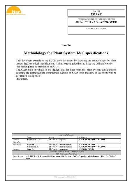
IDM UID<br />
353AZY<br />
VERSION CREATED ON / VERSION / STATUS<br />
08 Feb 2011 / 3.3 / APPROVED<br />
EXTERNAL REFERENCE<br />
How To<br />
<strong>Methodology</strong> <strong>for</strong> <strong>Plant</strong> <strong>System</strong> I&C <strong>specifications</strong><br />
This document completes the PCDH core document by focusing on methodology <strong>for</strong> plant<br />
system I&C technical <strong>specifications</strong>. It aims to give guidelines to issue the deliverables <strong>for</strong><br />
the design phase as mentioned in PCDH.<br />
The CAD tools involved in the design and the links with the plant system configuration<br />
database are addressed and commented. Details on CAD tools and how to use them will be<br />
developed in a specific<br />
document.<br />
Approval Process<br />
Name Action Affiliation<br />
Author Journeaux J.- Y. 08-Feb-2011:signed IO/DG/DIP/CHD/CIT/CODAC<br />
CoAuthor<br />
Reviewers Klotz W.- D.<br />
Wallander A.<br />
21-Feb-2011:recommended<br />
08-Feb-2011:recommended<br />
Approver Bora D. 23-Feb-2011:approved IO/DG/DIP/CHD<br />
Document Security: level 1 (IO unclassified)<br />
RO: Journeaux Jean-Yves<br />
Read Access<br />
IO/DG/DIP/CHD/CIT<br />
IO/DG/DIP/CHD/CIT/CODAC<br />
AD: ITER, AD: External Collaborators, AD: Section - CODAC, project administrator, RO, LG: CODAC<br />
team<br />
PDF generated on 23-Feb-2011
Change Log<br />
Version Latest Status Date Description of Change<br />
v3.3 Approved 08 Feb 2011 Update after PCDH v6 external review<br />
v3.2 Signed 05 Jan 2011 John Poole review, version <strong>for</strong> PCDH v6 external review<br />
v3.1 Signed 03 Jan 2011 New version to be reviewed in scope of PCDH v6.<br />
if(typeof editorarray == 'object')<br />
{<br />
editorarray.push('ctl00_MasterPlaceHolder_DocumentView1_ctl01_ctl00_ctl00<br />
_ctl16_ver_description')<br />
}<br />
v3.0 Signed 03 Jan 2011 New version to be reviewed in scope of PCDH v6.<br />
v2.0 Approved 28 Jan 2010 PCDH v5 review included<br />
v1.3 Signed 26 Jan 2010 Update after official review <strong>for</strong> PCDH v5<br />
v1.2 Signed 10 Dec 2009 Review of PCDH docs references<br />
v1.1 Signed 10 Dec 2009 IDM ref updated<br />
v1.0 In Work 10 Dec 2009<br />
PDF generated on 23-Feb-2011
Records of revisions<br />
Revision Date Description Modified Pages<br />
0 04/09/2009 First draft <strong>for</strong> PCDH v5<br />
1 10/09/2009 First CODAC review comments included 2 to 9<br />
2.1 21/09/2009 Second CODAC review comments included 2 to 14<br />
2.2 30/10/2009 IO review comments included 2 to 14<br />
2.3 25/01/2010 J Poole and IO review 2 to 14<br />
3.0 15/11/2010 New version <strong>for</strong> PCDH v6, maturity tables and FBS<br />
added. Other sections simplified, no change on inputs<br />
and deliverable lists and definition.<br />
3.1 17/12/2010 Intermediate version<br />
2 to 4<br />
3.2 05/01/2011 J Poole review All pages<br />
3.3 08/02/2011 Final version <strong>for</strong> PCDH v6.1 Cover page<br />
<strong>Methodology</strong> <strong>for</strong> plant system I&C <strong>specifications</strong> v3.3 Page 1 of 30
TABLE of CONTENTS<br />
1. INTRODUCTION .........................................................................................................................................4<br />
1.1. PCDH context ....................................................................................................................................4<br />
1.2. Document scope ...............................................................................................................................4<br />
1.3. Document identifiers.........................................................................................................................5<br />
1.4. Topics remaining to be addressed ..................................................................................................5<br />
1.5. Review, validation and thanks .........................................................................................................5<br />
1.6. Acronyms...........................................................................................................................................6<br />
1.7. Related documents ...........................................................................................................................6<br />
2. PLANT SYSTEM I&C TECH SPECS ..........................................................................................................7<br />
2.1. I&C technical <strong>specifications</strong> in general...........................................................................................7<br />
2.2. PCDH deliverables <strong>for</strong> plant system I&C technical <strong>specifications</strong>...............................................7<br />
2.3. Inputs <strong>for</strong> plant system I&C technical <strong>specifications</strong> ....................................................................9<br />
2.4. Review of PCDH deliverables <strong>for</strong> I&C <strong>specifications</strong>...................................................................10<br />
2.5. CAD tools involved in plant system I&C design activities ..........................................................11<br />
2.6. Summary of data directions between databases .........................................................................11<br />
3. General scheme <strong>for</strong> I&C <strong>specifications</strong> .................................................................................................12<br />
4. <strong>Methodology</strong> <strong>for</strong> plant system I&C architecture definition ..................................................................13<br />
4.1. What is proposed <strong>for</strong> plant system I&C architecture ...............................................................13<br />
4.2. The methodology <strong>for</strong> defining this I&C architecture ...................................................................13<br />
4.3. PCDH documents <strong>for</strong> I&C design ..................................................................................................15<br />
4.4. Illustrations <strong>for</strong> complete I&C <strong>specifications</strong> ...............................................................................15<br />
Example of diagrams........................................................................................................................................16<br />
<strong>Methodology</strong> <strong>for</strong> plant system I&C <strong>specifications</strong> v3.2 Page 2 of 22
FIGURES<br />
Figure 1: PCDH documents structure __________________________________________________________5<br />
Figure 2: plant system I&C life-cycle__________________________________________________________10<br />
Figure 3: Summary of data directions with the plant system configuration database and ICP/ PLM<br />
engineering database. _______________________________________________________12<br />
Figure 4: Generic scheme of ITER design <strong>for</strong> a functional design PA type. ____________________________13<br />
Figure 5: Generic scheme of ITER design <strong>for</strong> a detailed design PA type ______________________________13<br />
Figure 6: Example of diagram <strong>for</strong> I&C functions, outcome of step2 __________________________________14<br />
Figure 7: illustration of the characterisation of data links and I&C functions __________________________15<br />
Figure 8: From the FBS to the plant system I&C architecture ______________________________________15<br />
Figure 9: Example of PFD: Cryo-distribution system, main component and part of sensors are mentioned ___17<br />
Figure 10: PFD example on ACB, zoom _______________________________________________________18<br />
Figure 11: In this schema, the PFD is used to illustrate the process description document (text) to identify<br />
active components according to the operation mode________________________________19<br />
Figure 12: PID example on the ACB: details of instrumentation ____________________________________20<br />
Figure 13: Example of electrical diagram <strong>for</strong> process description: MV 22/6.6 and 0.4kV distribution and<br />
22/0.4kV distribution ________________________________________________________21<br />
Figure 14: Example of electrical diagram <strong>for</strong> process description: detail of MV 22/6.6 and 0.4kV<br />
distribution and 22/0.4kV distribution ___________________________________________22<br />
<strong>Methodology</strong> <strong>for</strong> plant system I&C <strong>specifications</strong> v3.2 Page 3 of 22
1.1. PCDH context<br />
1. INTRODUCTION<br />
The <strong>Plant</strong> Control Design Handbook (PCDH) [RD2] defines methodology, standards, <strong>specifications</strong> and<br />
interfaces applicable to ITER <strong>Plant</strong> <strong>System</strong>s Instrumentation & Control (I&C) <strong>System</strong> life cycle. I&C standards<br />
are essential <strong>for</strong> ITER to:<br />
• Integrate all plant systems into one integrated control system.<br />
• Maintain all plant systems after delivery acceptance.<br />
• Contain cost by economy of scale.<br />
PCDH comprises a core document which presents the plant system I&C life cycle and recaps the main rules to<br />
be applied to the plant system I&Cs <strong>for</strong> conventional controls, interlocks and safety controls. Some I&C topics<br />
are explained in greater detail in dedicated documents associated with PCDH as presented in Figure 1.<br />
This document is one of them.<br />
PCDH core and satellite documents: v6<br />
INTERLOCK CONTROLS<br />
Guidelines <strong>for</strong> the design of the PIS (3PZ2D2)<br />
PIS, PS I&C and CIS integration<br />
Guidelines <strong>for</strong> PIS configuration<br />
Management of local interlock functions<br />
Management of interlock data<br />
OCCUPATIONAL SAFETY CONTROLS<br />
Rules and guidelines <strong>for</strong> PSS design<br />
NUCLEAR PCDH (2YNEFU)<br />
CATALOGUES <strong>for</strong> PS CONTROL<br />
Slow controllers products (333J33)<br />
Fast controller products (345X28)<br />
Cubicle products (35LXVZ)<br />
Network products<br />
PS CONTROL DESIGN<br />
<strong>Plant</strong> system I &C architecture (32GEBH)<br />
<strong>Methodology</strong> <strong>for</strong> PS I &C <strong>specifications</strong> (353AZY)<br />
CODAC Core <strong>System</strong> Overview (34SDZ5)<br />
Core PCDH (27LH2V)<br />
<strong>Plant</strong> system control philosophy<br />
<strong>Plant</strong> system control Life Cycle<br />
<strong>Plant</strong> system control <strong>specifications</strong><br />
CODAC interface <strong>specifications</strong><br />
Interlock I&C specification<br />
Safety I&C specification<br />
I&C CONVENTIONS<br />
I&C Signal and variable naming (2UT8SH)<br />
ITER CODAC Glossary (34QECT)<br />
ITER CODAC Acronym list (2LT73V)<br />
PS SELF DESCRIPTION DATA<br />
Self description schema documentation (34QXCP)<br />
PS CONTROL INTEGRATION<br />
The CODAC -PS Interface (34V362)<br />
PS factory acceptance plan (3VVU9W)<br />
ITER alarm system management (3WCD7T)<br />
ITER operator user interface (3XLESZ)<br />
Guidelines <strong>for</strong> archiving<br />
Specifications <strong>for</strong> HPN<br />
Specifications <strong>for</strong> time stamping<br />
PS CONTROL DEVELOPMENT<br />
I&C signal interface (3299VT)<br />
PLC software engineering handbook (3QPL4H)<br />
Guidelines <strong>for</strong> fast controllers (333K4C)<br />
CODAC software development environment (2NRS2K)<br />
Guidelines <strong>for</strong> signal conditioning<br />
Guidelines <strong>for</strong> I &C cubicle configurations<br />
TEMPLATES and ILLUSTRATIONS<br />
CWS case study <strong>specifications</strong> (35W299)<br />
LCC and SCC prototypes<br />
PS simulators : slow, fast, interlocks<br />
Legend<br />
This document<br />
Available and approved<br />
Expected<br />
(XXXXXX) IDM ref.<br />
1.2. Document scope<br />
Figure 1: PCDH documents structure<br />
This document completes the PCDH core document by focusing on methodology <strong>for</strong> plant system I&C design,<br />
see Figure 1. The scope is plant system I&C design <strong>for</strong> conventional, interlock and occupational safety<br />
controls; this document does not address Safety controls which are IEC61508 relevant.<br />
As a general statement, the plant system I&C design will be driven first by the plant system process and then<br />
by the plant system operation.<br />
Specific attention is given to the definition of the plant system process. Usually the process description is<br />
defined by defining the way the plant system components are operated, using text documents and process<br />
flow diagrams. This document proposes in addition, an approach based on a functional description of the plant<br />
system in order to obtain a working solution <strong>for</strong> the plant system I&C architecture.<br />
CAD tools are involved in the plant system I&C design; their links with the plant system configuration database<br />
are addressed and the specific features which may be required with these tools are clarified . Details of these<br />
tools and the way to use them will be developed in a specific document.<br />
<strong>Methodology</strong> <strong>for</strong> plant system I&C <strong>specifications</strong> v3.2 Page 4 of 22
1.3. Document identifiers<br />
Table 1 provides the full list of identifiers used in this document. The recommendations raised in this document<br />
as <strong>for</strong> the other PCDH satellite documents are mainly guidelines; some are rules and in such a case they are<br />
identified by a star symbol.<br />
As a general rule, the release of this document, like all the documents associated with PCDH mentioned in<br />
Figure 1, will be followed by an immediate update of the core PCDH so that the core PCDH is a single<br />
document containing all the mandatory rules applicable to plant system I&C. In this way it will be easier <strong>for</strong> the<br />
user to understand the requirements.<br />
AD<br />
GL<br />
RD<br />
<br />
Table 1: Paragraph identifiers<br />
Applicable Document<br />
Glossary item<br />
Reference Document<br />
Rules referenced in core PCDH<br />
1.4. Topics remaining to be addressed<br />
The details of the following topics will be addressed in the next version of this document:<br />
CAD tools data export<br />
1.5. Review, validation and thanks<br />
It is proposed this document is reviewed with the following objectives:<br />
<br />
Check compliance with ITER need and configuration.<br />
Check impact on manufacturing and technical optimisation.<br />
As a reference document associated with PCDH, the validation process of this document is similar to that of<br />
the core PCDH, involving the I&C IPT team and other IO people involved in I&C activities. Thanks to the<br />
people who take the time <strong>for</strong> this review.<br />
<strong>Methodology</strong> <strong>for</strong> plant system I&C <strong>specifications</strong> v3.2 Page 5 of 22
1.6. Acronyms<br />
Table 2 shows the acronyms used in this document. The relevant acronyms have been extracted from the<br />
complete list in PCDH .<br />
Acronym Item<br />
ANSI 1. American National Standard Institute<br />
CAD Computer-Aided Design<br />
CHD CODAC & IT, Heating & Current Drive, Diagnostics<br />
CODAC COntrol, Data Access and Communication<br />
DA Domestic Agency<br />
DO Design Office<br />
FAT Factory Acceptance Tests<br />
HMI Human Machine Interface<br />
ICP ITER Collaborative Plat<strong>for</strong>m<br />
I&C Instrumentation & Control<br />
IO ITER Organization<br />
I/O Inputs and Outputs<br />
IPT Integrated Product Team<br />
LCC Local Control Cubicle<br />
PCDH <strong>Plant</strong> Control Design Handbook<br />
PFD Process Flow Diagrams<br />
PLC Programmable Logic Controller<br />
P&ID Process and Instrumentation Diagram<br />
PIS <strong>Plant</strong> Interlock <strong>System</strong><br />
PS <strong>Plant</strong> <strong>System</strong><br />
PS OS <strong>Plant</strong> system Operation State<br />
PSH <strong>Plant</strong> <strong>System</strong> Host<br />
PSS <strong>Plant</strong> Safety <strong>System</strong><br />
PV Process Variable<br />
RAMI Reliability, Availability, Maintainability and Inspectability<br />
SAT Site Acceptance Tests<br />
SCC Signal Conditioning Cubicle<br />
SRD <strong>System</strong> Requirement Document<br />
TBC To Be Confirmed<br />
TBD To Be Defined<br />
Table 2: Abbreviations and acronyms<br />
1.7. Related documents<br />
ITER Numbering <strong>System</strong> <strong>for</strong> Parts/Components (ITER_D_28QDBS)<br />
<strong>Plant</strong> Control Design Handbook (PCDH) (ITER_D_27LH2V)<br />
I&C signal and process variable naming convention (ITER_D_2UT8SH)<br />
Signal processing <strong>for</strong> I&C (ITER_D_3299VT)<br />
Room book <strong>for</strong> buildings<br />
CAD Manual - Section 14 - Diagram Guidelines (ITER_D_35CY6V)<br />
Function Analysis Diagram Tool Specification (ITER_D_3NSG6U)<br />
CWS case study <strong>specifications</strong> (ITER_D_35W299)<br />
<strong>Methodology</strong> <strong>for</strong> plant system I&C <strong>specifications</strong> v3.2 Page 6 of 22
2. PLANT SYSTEM I&C TECH SPECS<br />
2.1. I&C technical <strong>specifications</strong> in general<br />
'In general, the technical <strong>specifications</strong> <strong>for</strong> any plant system I&C are the result of:<br />
- A scope definition which defines the controls needed in order to get suitable and safe operation<br />
whatever the configuration and context of operation. This item is driven by the plant system<br />
process and by the plant system operation.<br />
- Rules <strong>for</strong> I&C design which are mandatory requirements set up <strong>for</strong> several purposes; mainly to<br />
enable the integration of the plant system I&C in a larger infrastructure and to reduce the cost of<br />
maintenance.<br />
- Guidelines which have same purpose as rules but are recommendations to be adjusted depending<br />
on the plant system configuration and specificity.<br />
PCDH requires a set of deliverables to get a definition of scope: they are the deliverables of the I&C lifecycle<br />
<strong>for</strong> the design phase, (see chapter 3 of PCDH).<br />
Rules and guidelines to be applied are defined in PCDH chapter 4 and detailed in the related satellite<br />
documents. See Figure 1.<br />
2.2. PCDH deliverables <strong>for</strong> plant system I&C technical <strong>specifications</strong><br />
These PCDH deliverables <strong>for</strong> I&C <strong>specifications</strong> are:<br />
[D1]<br />
[D2]<br />
[D3]<br />
[D4]<br />
[D5]<br />
[D6]<br />
[D7]<br />
[D8]<br />
[D9]<br />
<strong>Plant</strong> system I&C architecture.<br />
<strong>Plant</strong> system I&C boundary definition.<br />
<strong>Plant</strong> systems I&C integration plan.<br />
<strong>Plant</strong> system P&IDs, mechanical and electrical drawings and diagrams needed <strong>for</strong> I&C<br />
<strong>specifications</strong>.<br />
<strong>Plant</strong> system controller(s) per<strong>for</strong>mance and configuration requirements.<br />
List of inputs and outputs (I/O) of the I&C controllers.<br />
List of the Process Variables handled by the plant system I&C controllers.<br />
Configuration of I&C cubicles.<br />
Description of plant system state machines.<br />
Table 3 defines the content of each deliverable:<br />
PCDH ID<br />
D1<br />
D2<br />
D3<br />
Sub<br />
Deliverable<br />
D1A<br />
D1B<br />
D1C<br />
Content<br />
Document introducing the main plant system functions and the main requirements<br />
<strong>for</strong> the plant system I&C <strong>specifications</strong>. A CODAC template is available.<br />
For each main plant system function, CAD diagrams including detailed I&C<br />
functions and links. Characterization of the functions. A CODAC template is<br />
available; this document provides additional details on how to issue this<br />
deliverable.<br />
Whole plant system I&C architecture including conventional, interlock and<br />
occupational safety controls. This architecture is a compilation of the D1Bs.<br />
D2A<br />
Details of data exchange with other plant systems. Derived from D1B and D1C<br />
documents.<br />
D2B Physical I&C interfaces with other plant systems, mainly PBS 45, 46 and 48.<br />
D3A<br />
D3B<br />
FAT I&C scenarios <strong>for</strong> each plant system procurement. A CODAC template is<br />
available.<br />
SAT I&C scenario <strong>for</strong> the whole plant system. A CODAC template is available.<br />
<strong>Methodology</strong> <strong>for</strong> plant system I&C <strong>specifications</strong> v3.2 Page 7 of 22
PCDH ID<br />
D4<br />
D5<br />
D6<br />
D7<br />
D8<br />
D9<br />
Sub<br />
Deliverable<br />
D4A<br />
D4B<br />
D4C<br />
D5A<br />
D5B<br />
D5C<br />
D6<br />
D7<br />
D8<br />
D9<br />
Content<br />
P&IDs CAD diagrams <strong>for</strong> instrumentation definition. Final diagrams are provided<br />
by the I&C supplier.<br />
CAD diagrams <strong>for</strong> I&C cabling and I&C cubicle location. Final diagrams are<br />
provided by the I&C supplier.<br />
CAD diagrams <strong>for</strong> I&C cable routing and characterization of the instrumentation<br />
cables. Final diagrams are provided by the I&C supplier.<br />
Controller network configuration, Input/Output amount and type, data sampling<br />
rate, requirement <strong>for</strong> time synchronisation and connection to HPN.<br />
Definition of technology <strong>for</strong> each I&C controller. PCDH standards apply.<br />
Rack hardware configuration <strong>for</strong> each I&C controller. PCDH standards apply.<br />
Details of inputs and outputs including name, type, data sampling rate, resolution,<br />
allocation to I&C controller and location, <strong>for</strong> each I/O.<br />
Details of data exchange with CODAC including name, allocation of PSH, time<br />
stamping scheme, data flow profile depending on COS and organised by I&C<br />
function. PV properties.<br />
Hardware configuration of I&C cubicle <strong>for</strong> LCC and SCC. For each cubicle<br />
definition of: cubicle type and configuration, location of controller racks in the<br />
cubicle, cable entry, cable interface, cubicle environment, cubicle HVAC, specific<br />
configurations if any. Guidelines will be proposed in PCDH v7.<br />
Sequential function charts showing the plants system operating states, links<br />
between these states and condition from states to states. Specific plant operating<br />
states and COS are included.<br />
Table 3: content of each PCDH deliverable <strong>for</strong> I&C <strong>specifications</strong><br />
Among all these documents, the most important is the deliverable D1 <strong>for</strong> the plant system I&C architecture.<br />
Additional details <strong>for</strong> determining a suitable architecture is provided in chapter 4 of this document.<br />
Deliverable D2 is an outcome of D1 focusing on interfaces.<br />
Deliverable D3 <strong>for</strong> plant system I&C integration should be considered in the scope of the whole plant system<br />
integration. Hence, it should be incorporated in the overall plan and scenario <strong>for</strong> plant system integration.<br />
Deliverable D4 <strong>for</strong> CAD diagrams is mentioned in this list of technical documents <strong>for</strong> I&C specification, but<br />
these CAD diagrams are also issued <strong>for</strong> other purposes such as process design, piping and cabling. Hence<br />
they are common deliverables shared with other topics of the plant system design.<br />
Deliverable D5 addresses the controller hardware configuration. The details of this configuration will be<br />
determined mainly by the I&C supplier. It is mentioned in this list in order to give general requirements <strong>for</strong> this<br />
configuration such as compliance with HW standards. This deliverable is also partially an outcome of D1.<br />
Deliverable D6 is another outcome of D1 focusing on signals connected to the controllers.<br />
Deliverable D7 is again an outcome of D1 focused on interface with CODAC infrastructure.<br />
Deliverable D8 provides general requirements of I&C cubicle HW configuration. As <strong>for</strong> D5, the details of this<br />
configuration will be determined mainly by the I&C supplier. It is mentioned in this list in order to give general<br />
requirements <strong>for</strong> this configuration such as compliance with standards and cabling rules.<br />
Deliverable D9 is mentioned to be able to prepare the integration of the plant system operation and check<br />
compliance with Common Operating States and state machines.<br />
<strong>Methodology</strong> <strong>for</strong> plant system I&C <strong>specifications</strong> v3.2 Page 8 of 22
PS I&C Life Cycle: from design to operation & maintenance<br />
PS design phase<br />
EDH<br />
PCDH<br />
Inputs <strong>for</strong><br />
I&C design<br />
PS I&C<br />
design<br />
PS<br />
design<br />
review<br />
PS manufacture phase<br />
PCDH<br />
PCDH<br />
PS<br />
manufacture<br />
including I&C<br />
PS FAT<br />
including<br />
I&C<br />
PCDH<br />
PS integration phase<br />
PS on site<br />
Installation<br />
including I&C<br />
PCDH<br />
PS SAT<br />
including<br />
I&C<br />
PCDH<br />
PS integrated<br />
commissioning<br />
Operation and<br />
maintenance phase<br />
PCDH<br />
Operation &<br />
maintenance<br />
Figure 2: plant system I&C life-cycle<br />
2.3. Inputs <strong>for</strong> plant system I&C technical <strong>specifications</strong><br />
In order to initiate the design activity, a set of inputs are assumed to be available. The main inputs are:<br />
<strong>Plant</strong> system I&C operation and control philosophy: this gives some high level requirements<br />
to be used <strong>for</strong> the design of the plant system I&C. These requirements are used <strong>for</strong> the<br />
deliverable D1 mainly.<br />
<strong>Plant</strong> system functional analysis: this is another input to be used <strong>for</strong> D1. This functional<br />
analysis is operation oriented and is normally aligned with the functional breakdown<br />
per<strong>for</strong>med in scope of RAMI analysis.<br />
<strong>Plant</strong> system PFDs, mechanical and electrical drawings and diagrams needed at the<br />
conceptual design phase.<br />
A list and short description of main plant system operating states <strong>for</strong> plant system operation.<br />
<strong>Plant</strong> system risk analysis and I&C RAMI requirements: this determines the main risks to<br />
protect the plant system.<br />
<strong>System</strong> Interface Control Documents (S-ICDs) relevant <strong>for</strong> the plant system I&C.<br />
List and <strong>specifications</strong> of the main protection functions to implement in the plant system I&C.<br />
This is issued from I5, may be merged with I5.<br />
List and <strong>specifications</strong> of the main safety functions to implement within the plant system or<br />
with respect to other plant systems. Similar to I7 <strong>for</strong> Safety.<br />
Mapping of deliverables / inputs: Dependency of inputs and deliverables (top row) on other deliverables (left<br />
column):<br />
<strong>Methodology</strong> <strong>for</strong> plant system I&C <strong>specifications</strong> v3.2 Page 9 of 22
D1 D2 D3 D4 D5 D6 D7 D8 D9 I1 I2 I3 I4 I5 I6 I7 I8<br />
D1 - - - - - - - - - X X X - X - X X<br />
D2 X - - - - - - - - - - - - - X - -<br />
D3 X X - - - - - - - - - - - - - - -<br />
D4 X X - - - - - - - - - - X - - - -<br />
D5 X X - X - - - - - - - - - - - - -<br />
D6 X X - X X - - - - - - - - - - - -<br />
D7 X X - X X X - - - - - - - - - - -<br />
D8 X X X X X X - - - - - - - - - -<br />
D9 X X - X X X X - - - - - - - - - -<br />
<strong>Methodology</strong> <strong>for</strong> plant system I&C <strong>specifications</strong> v3.2 Page 10 of 22
2.4. Review of PCDH deliverables <strong>for</strong> I&C <strong>specifications</strong>.<br />
Table 4 provides the maturity level of each deliverable required <strong>for</strong> each of the design reviews, Conceptual<br />
Design Review (CDR), Preliminary Design Review (PDR) and Final Design Review (FDR).<br />
Dn<br />
D1<br />
D2<br />
D3<br />
D4<br />
D5<br />
D6<br />
D7<br />
PCDH ID<br />
Name<br />
<strong>Plant</strong> system I&C architecture.<br />
<strong>Plant</strong> system I&C boundary<br />
definition.<br />
<strong>Plant</strong> systems I&C integration<br />
plan.<br />
<strong>Plant</strong> system P&IDs,<br />
mechanical and electrical<br />
diagrams needed <strong>for</strong> I&C<br />
<strong>specifications</strong>.<br />
Content<br />
Document availability and review status <strong>for</strong> reviews<br />
CDR PDR FDR<br />
D1A - Fully consolidated version -<br />
D1B -<br />
Partially consolidated Fully consolidated<br />
version<br />
version<br />
D1C -<br />
Partially consolidated Fully consolidated<br />
version<br />
version<br />
D2 - Fully consolidated version -<br />
D3 -<br />
D4 -<br />
<strong>Plant</strong> system controller(s)<br />
per<strong>for</strong>mance and configuration<br />
requirements. D5C -<br />
List of inputs and outputs (I/O)<br />
of the I&C controllers.<br />
List of the process variables<br />
(PV) handled by the plant<br />
system I&C controllers<br />
Partially consolidated<br />
version<br />
Partially consolidated<br />
version<br />
Fully consolidated<br />
version<br />
Fully consolidated<br />
version<br />
D5A - Fully consolidated version -<br />
D5B - Fully consolidated version -<br />
Partially consolidated<br />
version<br />
Partially consolidated<br />
D6 -<br />
version <strong>for</strong> limited scope:<br />
only list of I/Os with name<br />
<strong>for</strong> each I&C controller.<br />
D7 -<br />
D8 Configuration of I&C cubicles. D6 -<br />
D9<br />
Description of plant system<br />
state machines.<br />
D7 -<br />
Partially consolidated<br />
version <strong>for</strong> limited scope:<br />
only list of PVs with name<br />
<strong>for</strong> each I&C function.<br />
Partially consolidated<br />
version <strong>for</strong> limited scope:<br />
definition of cubicle<br />
location and environment.<br />
Partially consolidated<br />
version <strong>for</strong> limited scope:<br />
definition of operating<br />
states<br />
Table 4: maturity levels depending on design reviews <strong>for</strong> I&C <strong>specifications</strong><br />
Fully consolidated<br />
version<br />
Fully consolidated<br />
version<br />
Fully consolidated<br />
version<br />
Fully consolidated<br />
version<br />
Fully consolidated<br />
version<br />
<strong>Methodology</strong> <strong>for</strong> plant system I&C <strong>specifications</strong> v3.2 Page 11 of 22
2.5. CAD tools involved in plant system I&C design activities<br />
CAD tools are required to issue the I&C <strong>specifications</strong> <strong>for</strong> D1, D4 and D8. These CAD tools address electrical,<br />
mechanical and fluid descriptions of the plant system; they are specified, selected and managed by the IO<br />
Design Office (IODO). Examples of such diagrams and drawings are given at the end of this document.<br />
The CAD diagrams and drawings will have to be updated throughout the whole life-cycle of the plant system.<br />
IO, DAs and industry will be involved in this update process.<br />
A specific CAD tool will be developed to support the <strong>specifications</strong> of the I&C functions (available by the<br />
beginning of 2011) <strong>for</strong> D1. Specifications of this CAD tool are available in [RD7].<br />
These Cad tools are managed by IO Design Office (DO) and shall be used <strong>for</strong> any of the diagrams and<br />
drawing types as listed in following table.<br />
Diagrams / Drawings type<br />
IO standard tools<br />
Mechanical drawings CATIA V5<br />
PFD diagrams See <strong>System</strong> Design<br />
P&ID diagrams See <strong>System</strong> Design<br />
Electrical diagrams See <strong>System</strong> Design<br />
Functional analysis diagrams See <strong>System</strong> Design<br />
Cubicle configuration drawings See Electrical Expert<br />
2.6. Summary of data directions between databases<br />
These diagrams and drawings and related data are stored in Design Office databases (See <strong>System</strong> Design<br />
and ICP/PLM). The idea is to use a part of these data <strong>for</strong> the configuration of the plant system I&C systems.<br />
Hence, Design Office databases and CODAC databases will have to exchange data to have a consistent<br />
design. Data links are summarized below:<br />
Process<br />
name<br />
P&ID CAD<br />
I&C Function<br />
Analysis<br />
<strong>Plant</strong> I&C<br />
Diagram<br />
See<br />
<strong>System</strong><br />
Design<br />
database<br />
Possible extraction<br />
<strong>Plant</strong> <strong>System</strong><br />
Configuration<br />
Database<br />
ICP<br />
Engineering Database<br />
Cubicle<br />
configuration<br />
Diagram<br />
Figure 3: Summary of data directions with the plant system configuration database and ICP/ PLM engineering<br />
database.<br />
<strong>Methodology</strong> <strong>for</strong> plant system I&C <strong>specifications</strong> v3.2 Page 12 of 22
3. General scheme <strong>for</strong> I&C <strong>specifications</strong><br />
<strong>Plant</strong> system I&C design will follow the ITER model <strong>for</strong> design which defines the three following phases:<br />
conceptual design, preliminary design and final design.<br />
Whichever phase is concerned, the deliverables listed in chapter 2 of this document shall be addressed<br />
and shall be issued and updated in compliance with the IO Design Office policy.<br />
The plant system I&C design will follow in a parallel way with the full plant system design and will share the<br />
same milestones <strong>for</strong> reviews: Conceptual, preliminary and final design reviews.<br />
Whatever the PA type: functional, detailed design or build to print, the PCDH deliverables shall be issued; only<br />
the responsibility <strong>for</strong> issuing them by IO and DAs changes depending on the date of the PA signature. See<br />
Figure 4 and Figure 5 <strong>for</strong> functional and detailed PA types.<br />
Whatever the PA type IO will have to approve these I&C <strong>specifications</strong>.<br />
Figure 4: Generic scheme of ITER design <strong>for</strong> a functional design PA type.<br />
Figure 5: Generic scheme of ITER design <strong>for</strong> a detailed design PA type<br />
<strong>Methodology</strong> <strong>for</strong> plant system I&C <strong>specifications</strong> v3.2 Page 13 of 22
4. <strong>Methodology</strong> <strong>for</strong> plant system I&C architecture definition<br />
4.1. What is proposed <strong>for</strong> plant system I&C architecture <br />
<br />
<br />
<br />
A Functional Breakdown <strong>System</strong> (FBS) to determine the process function of the plant system and to<br />
identify the I&C functions required to control the plant system.<br />
CAD diagrams and text documents giving details <strong>for</strong> each I&C function. The I&C functions and the<br />
data links between the I&C functions are characterized.<br />
A definition of the controllers to implement these I&C functions.<br />
A complete architecture showing all the plant system controllers of the plant system I&C and networks<br />
to implement the data links.<br />
This architecture addresses all conventional, interlock and safety controls. Nuclear safety controls are not<br />
included because they have to be segregated.<br />
4.2. The methodology <strong>for</strong> defining this I&C architecture<br />
<br />
<br />
<br />
<br />
Step1: Issue the D1A document, incorporate the FBS <strong>for</strong> the plant system and the main requirements<br />
<strong>for</strong> the I&C design coming from the plant system itself. These requirements include the philosophy <strong>for</strong><br />
I&C design (Input I1) and any specific requirement the PS RO would like to add.<br />
Step2: For each process function identified in the FBS, develop the CAD diagrams introducing the I&C<br />
functions required to control the process function, see illustration in Figure 6. Determine the data links<br />
which are required between these I&C functions and with other functions of the plant system and<br />
outside the plant system. Name these I&C functions and data links. Characterize these links and I&C<br />
function <strong>for</strong> data type, signal type, response time and SIC level. See illustration in Figure 7.<br />
Step3: Determine the controllers required to per<strong>for</strong>m these I&C functions. Pay attention to consistency<br />
<strong>for</strong> operation and technology required, in particular <strong>for</strong> time response and SIC level. See illustration in<br />
Figure 8.<br />
Step4: Determine the complete architecture of the plant system I&C with all controllers linked together<br />
by CODAC infrastructure networks. See illustration in Figure 8.<br />
HVPS<br />
51.HV.1<br />
RF source<br />
51.ANT1.CONF.PARA.L1<br />
HVPS<br />
51.HV.1<br />
HVPS control &<br />
51.ANT1.HVCM.L1<br />
mgmnt<br />
51.ANT1.HVPS<br />
51.ANT1.HVPS.MESM.L1<br />
Amplitude<br />
Mearement<br />
51.ANT1.HVPS.MESM.L2<br />
51.RS.1<br />
51.ANT1.FAFB.PROT.L1<br />
51.ANT1.HVRF.INTF.L1<br />
High Volt control &<br />
mgmnt<br />
51.ANT1.HVRF<br />
51.ANT1.FAFB.PROT.L2<br />
51.ANT1.HVRF.MESM.L2<br />
Amplitude<br />
Mearement<br />
51.RS.1<br />
51.RS.1<br />
51.ANT1.HVRF.MESM.L1<br />
51.ANT1.CONF.PARA.L4<br />
51.ANT1.FAFB.RFPW.L1<br />
51.ANT1.PROT.OVRV.L1<br />
CONF<br />
ANT2<br />
CORD<br />
HVPS<br />
HVRF<br />
51<br />
ANT1<br />
TEST<br />
PROT FAFB<br />
SPLR<br />
TLMN<br />
MATC HVDL<br />
PPTF<br />
HPLS<br />
51.ANT1.FAFB.CORD.L1<br />
51.ANT1.PCS.FAFB.L1<br />
ICH fast feedback<br />
Controller<br />
51.ANT1.FAFB<br />
ICH coordination<br />
51.ANT1.CORD<br />
51.ANT1.HVPS.PROT.L1<br />
51.ANT1.FAFB.CORD.L2<br />
Amplitude<br />
interlock control<br />
51.ANT1.PROT<br />
51.ANT1.PCS.CORD.L1<br />
51.ANT1.FAFB.MONI.L1<br />
51.ANT1.FAFB.MONI.L3<br />
Amplitude<br />
monitoring<br />
51.ANT1.MON1<br />
51.ANT1.MON1.L1<br />
PCS<br />
CODAC<br />
47<br />
45<br />
Figure 6: Example of diagram <strong>for</strong> I&C functions, outcome of step2<br />
<strong>Methodology</strong> <strong>for</strong> plant system I&C <strong>specifications</strong> v3.2 Page 14 of 22
Function definition<br />
Links<br />
Nb.<br />
IO - V<br />
Response<br />
time<br />
51.ANT1.CONF.PARA TBD 500 ms<br />
51.ANT1.CONF.PARA.L7 TBD 500 ms<br />
51.ANT1.CONF.PARA.L1<br />
to<br />
51.ANT1.CONF.PARA.L6<br />
51.ANT1.CORD.REFR.L1<br />
to<br />
51.ANT1.CORD.REFR.L5<br />
TBD<br />
TBD<br />
500 ms<br />
500 ms<br />
Purpose<br />
Configuration of parameters from PCS<br />
in to ICH coordination controller.<br />
ICH Coordination controller checks<br />
request <strong>for</strong> ICH range and limits w.r.t<br />
its current status, if request is valid then<br />
send back acknowledgement. If invalid<br />
request then send back the token<br />
in<strong>for</strong>mation about incorrect parameter<br />
requested <strong>for</strong> new request.<br />
Configuration of initial parameters in to<br />
HVPS, RF Synthesizer, RF Source,<br />
Fast feedback controller and Matching<br />
<strong>System</strong> respectively a typical pre-shot<br />
configuration by ICH coordination<br />
controller.<br />
Frequency reference <strong>for</strong> RF Frequency<br />
to IF conversion<br />
SIL<br />
0<br />
0<br />
0<br />
0<br />
Figure 7: illustration of the characterisation of data links and I&C functions<br />
Figure 8: From the FBS to the plant system I&C architecture<br />
<strong>Methodology</strong> <strong>for</strong> plant system I&C <strong>specifications</strong> v3.2 Page 15 of 22
4.3. PCDH documents <strong>for</strong> I&C design<br />
Topic<br />
<strong>Plant</strong> Control Design Handbook<br />
I&C signal and variable naming convention<br />
Self description schema documentation<br />
The CODAC - <strong>Plant</strong> <strong>System</strong> Interface<br />
<strong>Methodology</strong> <strong>for</strong> PS I&C design<br />
<strong>Plant</strong> system case studies <strong>for</strong> illustration<br />
IDM ref<br />
27LH2V<br />
2UT8SH<br />
34QXCP<br />
34V362<br />
353AZY<br />
35W299<br />
Status<br />
Available<br />
Available<br />
Available<br />
Available<br />
Available<br />
Available<br />
Table 6: documents <strong>for</strong> I&C <strong>specifications</strong><br />
Topic<br />
<strong>Plant</strong> Control Design Handbook<br />
I&C signal and variable naming convention<br />
ITER PLC (Slow Controller) catalogue<br />
CODAC Catalogue of I&C products – Fast Controllers<br />
Fast Controller Technical Note -Methods between<br />
Interconnected <strong>System</strong>s<br />
ITER Cubicles catalogue<br />
I&C signal interface guidelines<br />
I&C cubicle wiring configurations guidelines<br />
FAT and SAT scenarios<br />
Rules and guidelines <strong>for</strong> PIS design<br />
Rules and guidelines <strong>for</strong> PSS design<br />
Guidelines and templates <strong>for</strong> slow controller user software<br />
development<br />
Mini CODAC and PSH configuration user manuals<br />
IDM ref<br />
27LH2V<br />
2UT8SH<br />
333J63<br />
345X28<br />
333K4C<br />
35LXVZ<br />
3299VT<br />
-<br />
3VVU9W<br />
3PZ2D2<br />
-<br />
3QPL4H<br />
-<br />
Status<br />
Available<br />
Available<br />
Available<br />
Available<br />
Available<br />
Available<br />
Available<br />
To come beg. 2011<br />
Available<br />
Available<br />
To come beg. 2011<br />
Available<br />
To come 2011<br />
Table 7: documents <strong>for</strong> I&C manufacture<br />
4.4. Illustrations <strong>for</strong> complete I&C <strong>specifications</strong><br />
See the [RD8] document which provides a simple illustration <strong>for</strong> a case study which will be used to illustrate<br />
PCDH and CODAC core <strong>for</strong> standards, tools, guidelines and methods.<br />
<strong>Methodology</strong> <strong>for</strong> plant system I&C <strong>specifications</strong> v3.2 Page 16 of 22
Figure 9: Example of PFD: Cryo-distribution system, main component and part of sensors are mentioned<br />
<strong>Methodology</strong> <strong>for</strong> plant system I&C <strong>specifications</strong> v3.3 Page 17 of 30
Figure 10: PFD example on ACB, zoom<br />
<strong>Methodology</strong> <strong>for</strong> plant system I&C <strong>specifications</strong> v3.2 Page 18 of 22
Figure 11: In this schema, the PFD is used to illustrate the process description document (text) to identify active components according to the operation mode<br />
<strong>Methodology</strong> <strong>for</strong> plant system I&C <strong>specifications</strong> v3.2 Page 19 of 22
Figure 12: PID example on the ACB: details of instrumentation<br />
<strong>Methodology</strong> <strong>for</strong> plant system I&C <strong>specifications</strong> v3.2 Page 20 of 22
Figure 13: Example of electrical diagram <strong>for</strong> process description: MV 22/6.6 and 0.4kV distribution and 22/0.4kV distribution<br />
<strong>Methodology</strong> <strong>for</strong> plant system I&C <strong>specifications</strong> v3.2 Page 21 of 22
Figure 14: Example of electrical diagram <strong>for</strong> process description: detail of MV 22/6.6 and 0.4kV distribution and 22/0.4kV distribution<br />
<strong>Methodology</strong> <strong>for</strong> plant system I&C <strong>specifications</strong> v3.2 Page 22 of 22