PIS Operation and Maintenance - Iter
PIS Operation and Maintenance - Iter
PIS Operation and Maintenance - Iter

Create successful ePaper yourself
Turn your PDF publications into a flip-book with our unique Google optimized e-Paper software.
IDM UID<br />
7L9QXR<br />
VERSION CREATED ON / VERSION / STATUS<br />
24 Jan 2013 / 1.0/ Approved<br />
EXTERNAL REFERENCE<br />
Memor<strong>and</strong>um / Note<br />
<strong>PIS</strong> <strong>Operation</strong> <strong>and</strong> <strong>Maintenance</strong><br />
This document presents a preliminary study on future operation <strong>and</strong> maintenance of the <strong>PIS</strong><br />
that have impact on the design of the systems. The document is the first version of one of the<br />
PCDH Satellite Documents for the interlocks.<br />
Approval Process<br />
Name Action Affiliation<br />
Author Savouillan M. 24-Jan-2013:signed IO/DG/DIP/CHD/CSD/CDC<br />
CoAuthor Vergara Fern<strong>and</strong>ez A. 24-Jan-2013:signed IO/DG/DIP/CHD/CSD/PCI<br />
Reviewers Yonekawa I.<br />
Wall<strong>and</strong>er A.<br />
25-Jan-2013:recommended<br />
05-Feb-2013:recommended<br />
IO/DG/DIP/CHD/CSD/PCI<br />
IO/DG/DIP/CHD/CSD<br />
Approver Thomas P. 24-Mar-2013:approved IO/DG/DIP/CHD<br />
Document Security: level 1 (IO unclassified)<br />
RO: Vergara Fern<strong>and</strong>ez Antonio<br />
Read Access AD: ITER, AD: External Collaborators, AD: Division - Control System Division - EXT, AD: Section -<br />
CODAC - EXT, AD: Section - CODAC, project administrator, RO, LG: CODAC team, LG: Interlock Gang,<br />
AD: Only-staff<br />
PDF generated on 24-Mar-2013<br />
DISCLAIMER : UNCONTROLLED WHEN PRINTED – PLEASE CHECK THE STATUS OF THE DOCUMENT IN IDM
Title (Uid)<br />
Versio<br />
n<br />
Change Log<br />
Latest Status Issue Date Description of Change<br />
<strong>PIS</strong> <strong>Operation</strong> <strong>and</strong><br />
<strong>Maintenance</strong><br />
(7L9QXR_v1_0)<br />
<strong>PIS</strong> <strong>Operation</strong> <strong>and</strong><br />
<strong>Maintenance</strong><br />
(7L9QXR_v0_0)<br />
v1.0 Approved 24 Jan<br />
2013<br />
v0.0 In Work 06 Nov<br />
2012<br />
Version for PCDH v7<br />
PDF generated on 24-Mar-2013<br />
DISCLAIMER : UNCONTROLLED WHEN PRINTED – PLEASE CHECK THE STATUS OF THE DOCUMENT IN IDM
Table of Contents<br />
1 Introduction .....................................................................................................................................2<br />
1.1 PCDH context .........................................................................................................................2<br />
1.2 Document Scope ....................................................................................................................2<br />
1.3 Acronyms................................................................................................................................3<br />
1.4 Related documents ................................................................................................................3<br />
2 Principles.........................................................................................................................................4<br />
3 Interlock <strong>Operation</strong> <strong>and</strong> <strong>Maintenance</strong> Actions.............................................................................4<br />
4 Interlock <strong>Operation</strong> <strong>and</strong> <strong>Maintenance</strong> Reliability.........................................................................5<br />
5 Interlock <strong>Operation</strong> <strong>and</strong> <strong>Maintenance</strong> Tools ................................................................................6<br />
6 Interface ICS-CODAC......................................................................................................................7<br />
7 Interface <strong>PIS</strong>-CIS .............................................................................................................................8<br />
Page 1 of 8
1 Introduction<br />
1.1 PCDH context<br />
The Plant Control Design H<strong>and</strong>book (PCDH) [RD1] defines the methodology, st<strong>and</strong>ards, specifications<br />
<strong>and</strong> interfaces applicable to the whole life cycle of ITER plant instrumentation & control (I&C) systems.<br />
I&C st<strong>and</strong>ards are essential for ITER to:<br />
• Integrate all plant systems into one integrated control system.<br />
• Maintain all plant systems after delivery acceptance.<br />
• Contain cost by economy of scale.<br />
PCDH comprises a core document which presents the plant system I&C life cycle <strong>and</strong> recaps the main<br />
rules to be applied to the plant system I&Cs for conventional controls, interlocks <strong>and</strong> safety controls.<br />
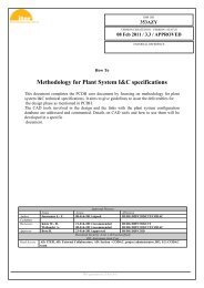
Some I&C topics are explained in greater detail in dedicated documents associated with PCDH as<br />
presented in Figure 1. This document is one of them.<br />
PCDH core <strong>and</strong> satellite documents: v7<br />
PS CONTROL DESIGN<br />
INTERLOCK CONTROLS<br />
Guidelines <strong>PIS</strong> design (3PZ2D2)<br />
Guidelines for <strong>PIS</strong> integration & config. (7LELG4)<br />
Management of local interlock functions (75ZVTY)<br />
<strong>PIS</strong> <strong>Operation</strong> <strong>and</strong> <strong>Maintenance</strong> (7L9QXR)<br />
Plant system I&C architecture (32GEBH)<br />
Methodology for PS I&C specifications (353AZY)<br />
CODAC Core System Overview (34SDZ5)<br />
I&C CONVENTIONS<br />
I&C Signal <strong>and</strong> variable naming (2UT8SH)<br />
ITER CODAC Glossary (34QECT)<br />
ITER CODAC Acronym list (2LT73V)<br />
OCCUPATIONAL SAFETY CONTROLS<br />
Guidelines for PSS design<br />
NUCLEAR PCDH (2YNEFU)<br />
CATALOGUES for PS CONTROL<br />
Slow controllers products (333J63)<br />
Fast controller products (345X28)<br />
Cubicle products (35LXVZ)<br />
Integration kit for PS I&C (C8X9AE)<br />
Core PCDH (27LH2V)<br />
Plant system control philosophy<br />
Plant system control Life Cycle<br />
Plant system control specifications<br />
CODAC interface specifications<br />
Interlock I&C specification<br />
Safety I&C specification<br />
PS CONTROL DEVELOPMENT<br />
I&C signal interface (3299VT)<br />
PLC software engineering h<strong>and</strong>book (3QPL4H)<br />
Guidelines for fast controllers (333K4C)<br />
CODAC software development environment (2NRS2K)<br />
Guidelines for I&C cubicle configurations (4H5DW6)<br />
CWS case study specifications (35W299)<br />
PS SELF DESCRIPTION DATA<br />
Self description schema documentation (34QXCP)<br />
PS CONTROL INTEGRATION<br />
The CODAC -PS Interface (34V362)<br />
PS I&C integration plan (3VVU9W)<br />
ITER alarm system management (3WCD7T)<br />
ITER operator user interface (3XLESZ)<br />
Guidelines for PON archiving (87N2B7)<br />
PS Operating State management (AC2P4J)<br />
Guidelines for Diagnostic data structure (354SJ3)<br />
Legend<br />
This document<br />
Available <strong>and</strong> approved<br />
Expected<br />
(XXXXXX) IDM ref.<br />
Figure 1: PCDH documents structure<br />
1.2 Document Scope<br />
This document presents the concepts of a preliminary study of future operation <strong>and</strong> maintenance of<br />
the part of the plant system I&C which implements the investment protection functions (<strong>PIS</strong>) which<br />
have an impact on its design. The document describes the operations that will be executed from the<br />
Control Room <strong>and</strong> the proposed tools. It also introduces the notion of procedures for supervising<br />
operation <strong>and</strong> maintenance activities.<br />
This document does not provide the guidelines to be followed by the plant system I&C designers<br />
for the implementation of the interfaces with the operation <strong>and</strong> maintenance tools. These are<br />
described in Guidelines for <strong>PIS</strong> design [RD2] for the hardware part <strong>and</strong> in Guidelines for <strong>PIS</strong><br />
Configuration <strong>and</strong> Integration [RD4] for the configuration part.<br />
Page 2 of 8
1.3 Acronyms<br />
Table 1 shows the acronyms used in this document. The relevant acronyms have been extracted<br />
from the complete list in PCDH.<br />
Acronym<br />
CIN<br />
CIS<br />
CODAC<br />
EPICS<br />
GOS<br />
HMI<br />
I&C<br />
ICS<br />
IO<br />
PCDH<br />
PIN<br />
<strong>PIS</strong><br />
PLC<br />
PON<br />
PS<br />
PSCC<br />
PSH<br />
Item<br />
Central Interlock Network<br />
Central Interlock System<br />
COntrol, Data Access <strong>and</strong> Communication<br />
Experimental Physics <strong>and</strong> Industrial Control System<br />
Global Operating State<br />
Human Machine Interface<br />
Instrumentation & Control<br />
Interlock Control System<br />
ITER Organization<br />
Plant Control Design H<strong>and</strong>book<br />
Plant Interlock Network<br />
Plant Interlock System<br />
Programmable Logic Controller<br />
Plant <strong>Operation</strong> Network<br />
Plant System<br />
Plant System Conventional Control<br />
Plant System Host<br />
Table 1: list of acronyms<br />
1.4 Related documents<br />
[RD1] Plant Control Design H<strong>and</strong>book (PCDH) (ITER_D_27LH2V)<br />
[RD2] Guidelines for <strong>PIS</strong> Design (ITER_D_3PZ2D2)<br />
[RD3] Management of Local Interlock Functions (ITER_D_75ZVTY)<br />
[RD4] Guidelines for <strong>PIS</strong> Configuration <strong>and</strong> Integration (ITER_D_7LELG4)<br />
[RD5] Central Interlock System Preliminary Design (CIS P-DDD) (ITER_D_CW5PKC)<br />
[RS1] IEC 61508 Functional safety of electrical/electronic/programmable electronic safety-related<br />
systems<br />
[RS2] IEC 61511 Functional safety – Safety instrumented systems for the process industry sector<br />
Page 3 of 8
2 Principles<br />
The plant systems constitute the main parts of the ITER facility <strong>and</strong> will be delivered by the project<br />
members with their own control systems (Plant System I&Cs). The plant interlock systems are the part<br />
of plant system I&Cs which implement investment protection functions.<br />
The CODAC (Control, Data Access <strong>and</strong> Communication) system is the central (supervisory) control<br />
system for the conventional plant control systems of ITER. CODAC is responsible for integrating all<br />
plant systems I&C <strong>and</strong> enabling operation of ITER as a single integrated facility, providing overall plant<br />
system coordination, supervision, alarm h<strong>and</strong>ling, data archiving <strong>and</strong> plant visualization (HMI).<br />
The Central Interlock System (CIS) implements the central protection functions via the Plant Interlock<br />
Systems (<strong>PIS</strong>). It also provides access to the local interlock data of the various plant interlock systems.<br />
The Interlock Control System (ICS) is in charge of the supervision <strong>and</strong> control of all the ITER<br />
components involved in the instrumented protection of the tokamak <strong>and</strong> its auxiliary systems. It<br />
comprises the Central Interlock System (CIS), the various plant interlock systems (<strong>PIS</strong>) <strong>and</strong> its<br />
networks. The ICS does not include the plant system sensors <strong>and</strong> actuators but it controls them.<br />
3 Interlock <strong>Operation</strong> <strong>and</strong> <strong>Maintenance</strong> Actions<br />
<strong>Operation</strong>s affecting the interlocks at ITER are classified into two main blocks: those routine operations<br />
executed during the daily operation of the tokamak <strong>and</strong> its associated systems, <strong>and</strong> the special ones<br />
carried out during commissioning or maintenance periods.<br />
<br />
Routine manual actions during machine operation:<br />
<br />
<br />
<br />
<br />
Monitoring of CIS <strong>and</strong> <strong>PIS</strong> status <strong>and</strong> of interlock-related process variables <strong>and</strong><br />
parameters: all interlock variables <strong>and</strong> parameters required for operation of the interlock<br />
systems will be displayed in the control room (machine states, central <strong>and</strong> local interlock<br />
events <strong>and</strong> actions, sensor <strong>and</strong> final element status, results of diagnostics).<br />
Post Mortem analysis: All the interlock variables <strong>and</strong> parameters will be logged <strong>and</strong><br />
appropriate post mortem analysis tools will be available to analyse interlock events.<br />
Reset (unlatch) of interlock functions, actuators <strong>and</strong> sensors: after the activation of an<br />
interlock function, either a central one (triggered by the CIS) or a local one (related to a<br />
given <strong>PIS</strong>), it is necessary to reset it before normal operation can continue. Indeed, the<br />
interlock system shall be designed in such a way that once it has placed the process in a<br />
safe state (comm<strong>and</strong>ing protection actions), it shall remain in the safe state until a reset has<br />
been initiated unless otherwise directed by specifications. The interlock system will always<br />
supervise that all the conditions required for safe operation are met, <strong>and</strong> will only allow the<br />
function to be reset as the last step after recovery from an interlock event. The reset shall<br />
be ignored by the system as long as the hazard (represented by a set of conditions <strong>and</strong><br />
events) has not been eliminated.<br />
Manual activation of ‘Permits’ <strong>and</strong> ‘Inhibits’: These are operator preventive comm<strong>and</strong>s<br />
that may be implemented in order to prevent the system for operating. A ‘Permit’/’Inhibit’ is<br />
granted by the interlock system only if all other conditions for a safe operation are met.<br />
<br />
Special (critical) manual actions during operation, maintenance <strong>and</strong> commissioning:<br />
<br />
By-pass <strong>and</strong> masking of interlock functions, signals <strong>and</strong> actions: an interlock function is<br />
put in place to protect ITER from incorrect operation <strong>and</strong> other external hazards. Therefore<br />
the masking of an interlock function should be avoided as far as possible. However, in<br />
some situations during commissioning it is necessary to isolate certain systems for testing<br />
<strong>and</strong> thus the related interlock functions have to be by-passed, or certain interlock signals<br />
masked. As these operations present a potential hazard, they must be managed in a way<br />
that the operator is aware at all times of the particular configuration <strong>and</strong> they should be<br />
easy to remove.<br />
Page 4 of 8
Detailed system diagnostics: In order to improve maintenance activities (repair <strong>and</strong><br />
preventive), detailed diagnostics must be available of hardware components (CPU, I/O<br />
modules…), of network status <strong>and</strong> performance <strong>and</strong> of communications links.<br />
Function configuration: for correct operation, an interlock function may require certain<br />
parameters to be provided manually, depending on the operating state of the machine or a<br />
given component. These parameters have a direct impact on the performance of the<br />
interlock function.<br />
Thresholds management: thresholds normally remain fixed during normal operation, but<br />
have to be tuned during commissioning <strong>and</strong> maintenance. A design philosophy based on<br />
two threshold levels is proposed: one changeable threshold to adjust to the operational<br />
window, <strong>and</strong> a second fixed threshold value related to the design value of the components<br />
or system.<br />
Software/firmware updates: interlock functions, controller software <strong>and</strong> firmware may<br />
evolve in time as a result of changing requirements or improvements. These changes<br />
require a full or partial stop of the system (temporary disconnection of a module while the<br />
others stay on-line) <strong>and</strong> imply a direct intervention in the cubicle. A verification <strong>and</strong><br />
validation cycle for each interlock function will have to be completed <strong>and</strong> changes will have<br />
to be thoroughly tested on the test bench.<br />
4 Interlock <strong>Operation</strong> <strong>and</strong> <strong>Maintenance</strong> Reliability<br />
The Interlock Control System is a critical system with very strict reliability constraints. In order to prevent<br />
hardware failures, several architectural strategies are put into practice, including redundancy, high<br />
integrity of the components, test <strong>and</strong> maintenance policies, etc. However, a system is more commonly<br />
prone to failure through its weakest link: human operations. In order to protect against such operational<br />
errors, several aspects are considered during the design:<br />
<br />
Physical <strong>and</strong> geographical protection:<br />
<br />
<br />
<br />
Access to critical components <strong>and</strong> the performance of dangerous operations is only<br />
possible from certain locations. Depending on the type of intervention, it may be better<br />
either to centralize the actions in the Main Control Room or to only allow intervention at the<br />
cubicle level.<br />
Interlock cubicles must be easily distinguishable <strong>and</strong> use different keys to other systems’<br />
cubicles.<br />
To avoid errors during maintenance in the field, accessible components must be kept as far<br />
away as possible from other systems’ components.<br />
<br />
Protections at the Human Machine Interface level:<br />
<br />
<br />
<br />
Role-based access to the system: a role-based login system manages the kind of actions<br />
that an operator can perform using the HMI depending on his/her expertise <strong>and</strong> rights.<br />
Identification <strong>and</strong> label: interlock data must be easily distinguishable <strong>and</strong> labels will permit<br />
the operator to be aware of the interlock classification for the monitoring data <strong>and</strong> controls<br />
displayed/accessible on the HMIs.<br />
Confirmation step: a repeat confirmation step minimizes unintentional operator comm<strong>and</strong>s.<br />
<br />
CIS automatic self-protection against human errors: this self-protection should cover all<br />
possible routine operational mistakes as well as some special cases, including:<br />
<br />
The interlock system should ignore a manual instruction from the operator if it may lead to a<br />
dangerous situation or if the conditions are not correct for changing its internal status (e.g.<br />
Page 5 of 8
equest to close the quench loop (reset) when there is still current in the coils; recovery of<br />
the ‘power permit’ in a power supply when cryo ‘not OK’).<br />
<br />
<br />
The interlock system should ignore an interlock mask when there is a dangerous machine<br />
status (e.g. interlock bypass not allowed during certain plasma scenarios or coil current<br />
levels).<br />
Specific self-protections will be developed for ‘routine’ operations such as unlatch or reset<br />
after an interlock function, or change in the GOS, to prevent any harm due to improper<br />
operator action.<br />
Other (organizational) protections are to be considered for the operation <strong>and</strong> maintenance phases:<br />
<br />
<br />
<br />
<br />
Procedures for operation <strong>and</strong> maintenance activities will be developed (techniques to be used,<br />
additional mitigation means, impact analysis, revalidation tests…). Reliable administrative<br />
procedures, in particular the procedures of masking interlock signals during commissioning, are<br />
crucial to limit <strong>and</strong> supervise the number of operations to be executed without the protection of<br />
the interlocks. It is proposed that an operations board/committee will be the only body<br />
authorized to change interlock set points.<br />
Operators <strong>and</strong> maintenance personnel must be trained.<br />
Periodic proof-tests following written procedures must be conducted to reveal dangerous<br />
failures undetected by diagnostics. These tests will include the sensors, the logic solvers <strong>and</strong><br />
the final elements. They may also include alarms. They will be defined to reach the specified<br />
objectives for reliability <strong>and</strong> availability but taking into account operational constraints described<br />
in operation h<strong>and</strong>book.<br />
On activation of an interlock function, the behaviour of the interlock system will be analysed<br />
(cause of the false trip or cause of the trigger, correct behaviour or discrepancy with expected<br />
behaviour, failures of part of the interlock system). These analyses facilitate the validation of the<br />
triggering assumptions made during the interlock system design <strong>and</strong> they allow the periodicity<br />
of the proof-tests to be adjusted if required.<br />
5 Interlock <strong>Operation</strong> <strong>and</strong> <strong>Maintenance</strong> Tools<br />
Two different platforms are available for the operation of the Interlock Control System from the Control<br />
Room:<br />
<br />
<br />
A dedicated ‘Interlock Desk’, directly connected to the Central Interlock Network, <strong>and</strong> thus with<br />
direct access to the CIS <strong>and</strong> the <strong>PIS</strong>, is proposed. This platform will allow all kinds of tasks<br />
(critical <strong>and</strong> non-critical) related to the interlock system to be performed (monitoring, operation,<br />
configuration <strong>and</strong> management). There are two different terminals/applications: a CIS<br />
Supervisor <strong>and</strong> an Engineering Workstation, both connected to the CIN <strong>and</strong> using different<br />
computer infrastructures. Communications avoid the use of the CODAC network infrastructure<br />
<strong>and</strong> interfaces, <strong>and</strong> the signals or comm<strong>and</strong>s exchanged with this are logged in the Critical<br />
Interlock Logging System. This ‘Interlock Desk’ is available in both control rooms, is provided by<br />
CIS (PBS.46) <strong>and</strong> is addressed in detail in the CIS Preliminary DDD [RD5].<br />
All generic non-critical tasks (routine-manual actions) affecting the <strong>PIS</strong> are available through<br />
CODAC. This platform makes use of the CODAC infrastructure, including terminals in the<br />
control room (EPICS) <strong>and</strong> network communications (Plant <strong>Operation</strong>s Network). The plant<br />
systems are encouraged to process the non-critical tasks via this CODAC interface. Indeed, the<br />
interlock systems (<strong>PIS</strong> <strong>and</strong> CIS) always monitor that all conditions required for safe operation<br />
are met. With this approach, flexibility during the operation of ITER is maximized without<br />
compromising its integrity. As a result of the close cohabitation of conventional <strong>and</strong> interlock<br />
data (indicators, alarms, controls) via this interface, it is necessary to clearly identify the<br />
interlock data.<br />
Page 6 of 8
Figure 2: Functional architecture<br />
In any case, no human intervention in the interlock cubicles is required or authorized during normal<br />
operations but during maintenance, most critical actions are available from the technical cubicles.<br />
These are managed <strong>and</strong> regulated by administrative procedures (i.e. modification of the PLC code after<br />
the changes have been validated on a test bench).<br />
6 Interface ICS-CODAC<br />
For operation <strong>and</strong> maintenance actions, the interface between CODAC <strong>and</strong> the Interlock Control<br />
System provides two access points:<br />
<br />
Communication between CODAC <strong>and</strong> <strong>PIS</strong>. The communication link is based on the direct<br />
connection of the <strong>PIS</strong> to the PON network according to the Guidelines for <strong>PIS</strong> Design [RD2]. An<br />
EPICS interface is required in order for the <strong>PIS</strong> to communicate with CODAC. Normally the<br />
PSH (provided by CODAC to each plant system I&C) acts as this interface. This communication<br />
occurs in two ways:<br />
<br />
<br />
<strong>PIS</strong> -> CODAC direction: the information transmitted includes all local process variables<br />
generated by the different <strong>PIS</strong> that are required by CODAC for archiving <strong>and</strong> monitoring<br />
purposes.<br />
CODAC -> <strong>PIS</strong> direction: The information transmitted includes all routine-manual<br />
comm<strong>and</strong>s concerning local interlock functions (e.g. unlatching or re-arming the equipment<br />
after a local interlock function has been triggered). <strong>Operation</strong>s allowed through this interface<br />
are normally dem<strong>and</strong>ed as a result of the triggering of a local interlock function, <strong>and</strong><br />
therefore will be available from the conventional operator desk. These comm<strong>and</strong>s are<br />
supervised by the system (<strong>PIS</strong>), so they are considered non critical. This interface is also<br />
used for the transmission of the timing signal.<br />
<br />
Communication between CODAC <strong>and</strong> CIS. The communication link is based on the connection<br />
of the CIS Supervisor module (PLC) to CODAC through an EPICS interface implemented in a<br />
Page 7 of 8
computer called the CIS-CODAC gateway (details about this interface addressed in the PBS.46<br />
Preliminary DDD [RD5]). This communication can occur in two ways:<br />
<br />
<br />
CIS -> CODAC direction: All interlock events, actions <strong>and</strong> variables generated by CIS are<br />
converted into EPICS PV’s <strong>and</strong> forwarded to be archived in CODAC or to be displayed on<br />
CODAC terminals.<br />
CODAC -> CIS direction: for non-critical communications. For the exchange of manual data<br />
or certain comm<strong>and</strong>s from the operators using the conventional operator desk in the control<br />
room if required. CODAC development or versioning tools could be used through this<br />
interface. This interface is also used for the transmission of the timing signal.<br />
7 Interface <strong>PIS</strong>-CIS<br />
The interface between the <strong>PIS</strong> <strong>and</strong> the CIS concerns three functions:<br />
<br />
<br />
<br />
Interface with CIS modules that implement central interlock functions (PLC or fast controllers).<br />
The data to be exchanged are mainly the <strong>PIS</strong> events, the <strong>PIS</strong> actions <strong>and</strong> the CIS actions.<br />
Interface with the CIS Supervisor module (PLC) that is in charge of the CIS interfaces with<br />
CODAC, with the CIS Supervisor (HMI) <strong>and</strong> with the Critical Interlock Logging System. The<br />
critical interlock data already forwarded to the CIS modules to implement central interlock<br />
functions will be displayed on the CIS Supervisor (HMI) <strong>and</strong> logged in the Critical Interlock<br />
Logging System by the connection of the CIS modules to the CIS Supervisor module (PLC)<br />
inside PBS.46 scope. Therefore it will not be forwarded a second time by the <strong>PIS</strong>. All the other<br />
interlock data including resets will be forwarded to the CIS Supervisor module (PLC) to be<br />
displayed or operated from the CIS Supervisor (HMI) <strong>and</strong> to be logged in the Critical Interlock<br />
Logging System. Moreover the CIS Supervisor Module (PLC) is also responsible for the<br />
propagation of the GOS to the <strong>PIS</strong>.<br />
Interface with the Engineering Workstation: The engineering workstations enable the software<br />
<strong>and</strong> configuration of the controllers <strong>and</strong> networks to be directly monitored from the control<br />
rooms through the proprietary controller software. The <strong>PIS</strong> shall authorize these connections.<br />
Page 8 of 8