Intorq BFK458 - Product Information - Industrial Clutch Parts Limited
Intorq BFK458 - Product Information - Industrial Clutch Parts Limited
Intorq BFK458 - Product Information - Industrial Clutch Parts Limited

You also want an ePaper? Increase the reach of your titles
YUMPU automatically turns print PDFs into web optimized ePapers that Google loves.
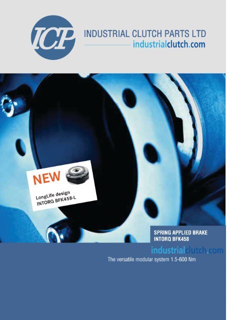
INTORQ I <strong>BFK458</strong> spring-applied brake I en 5/2008<br />
INTORQ <strong>BFK458</strong> - The modular system<br />
Our modular system forms the basis for a product range that<br />
offers versions tailored for almost any task. The <strong>BFK458</strong><br />
spring-applied brake, as a standard product, can be used<br />
anywhere, but its modular structure also meets the requirements<br />
of specific industries. Its strength lies in its versatility.<br />
Electromagnetically released spring-applied brakes are<br />
used wherever masses in motion have to be decelerated<br />
as quickly as possible or where masses must be held in a<br />
defined position. The braking force is applied by compression<br />
springs. Thus the braking torque generated by<br />
friction locking remains available in the deenergised status –<br />
even in the event of mains failure. The brake is released<br />
electromagnetically.<br />
The INTORQ <strong>BFK458</strong> range replaces the 14.448/14.449<br />
and 14.450 models of spring-applied brake. The main components<br />
of the modular system are the two basic modules<br />
E (adjustable braking torque) and N (braking torque not<br />
adjustable). The greatest degree of flexibility is achieved<br />
for a broad range of applications by the combination of<br />
the basic module with specific modules. This catalogue is<br />
intended to help you to select and to order the springapplied<br />
brake you require quickly and easily.<br />
The modular system for all applications<br />
| Brake motors<br />
| Materials handling technology<br />
| Cranes<br />
| Storage technology<br />
| <strong>Industrial</strong> trucks<br />
| Wood working machines<br />
| Stage machinery<br />
| Vehicles for the disabled<br />
| Automation technology<br />
| Regulated drives<br />
| Gate drives<br />
| Escalators<br />
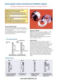
NEW: LongLife design INTORQ <strong>BFK458</strong>-L<br />
In high-cycle applications, spring-applied brakes are subject<br />
to two kinds of stress. Due to the large number of load<br />
alternations, the service life of the brake is determined both<br />
by the mechanical components of the brake itself and the<br />
useful life of the rotor, which is based on friction energy. In<br />
particular, the rotor/hub connection, the springs and the<br />
sleeve bolts are subject to wear due to the number of load<br />
cycles. Based on the components mentioned, without<br />
additional measures the service life of spring-applied brakes<br />
is limited to 1x10 6 to 4x10 6 load cycles depending on the<br />
load. The new LongLife design guarantees a service life of<br />
the brake mechanism at least 10x10 6 switching cycles.<br />
2<br />
www.<strong>Industrial</strong><strong>Clutch</strong>.com
INTORQ I <strong>BFK458</strong> spring-applied brake I en 5/2008<br />
Contents<br />
<strong>Product</strong> key 4<br />
List of abbreviations 5<br />
<strong>Product</strong> information 6<br />
Principle of operation 7<br />
Example applications 8<br />
Technical data<br />
Braking torques 9<br />
E/N/L + basic module 10<br />
Flange + manual release<br />
Brake module N + 11<br />
centring flange<br />
Basic module N + 12<br />
Connection flange +<br />
basic module N<br />
Rated data 13<br />
Operating times 14<br />
Service life and wear 15<br />
Type code 21<br />
Bridge rectifier and<br />
half-wave rectifier BEG<br />
Spark suppressor 21<br />
INTORQ 14.198.00.Oò<br />
Bridge rectifiers and 22<br />
half-wave rectifiers BEG<br />
Fastening options 25<br />
Connection diagrams 26<br />
Mains voltage selection table 27<br />
Dimensioning<br />
Basic information 28<br />
Calculation example 29<br />
Order form 30<br />
Sales and service 32<br />
around the world<br />
Accessories<br />
Manual release/flange/ 16<br />
friction plate<br />
Centring flange/ 17<br />
connection flange/Seal<br />
Brake cover 18<br />
Microswitch 19<br />
Terminal box 20<br />
Double spring-applied brakes<br />
INTORQ <strong>BFK458</strong>,<br />
noise-reduced in the theatre<br />
Spring-applied brakes<br />
INTORQ <strong>BFK458</strong>,<br />
corrosion-resistant in cranes<br />
LongLife spring-applied brakes<br />
INTORQ <strong>BFK458</strong>-òòL<br />
in materials handling technology<br />
www.<strong>Industrial</strong><strong>Clutch</strong>.com<br />
3
INTORQ I <strong>BFK458</strong> spring-applied brake I en 5/2008<br />
INTORQ <strong>BFK458</strong>-òòò product key<br />
B F K 4 5 8 - òò ò<br />
<strong>Product</strong> group: Brakes<br />
<strong>Product</strong> family: Spring-applied brakes<br />
Type<br />
Sizes<br />
Design<br />
Sizes<br />
06, 08, 10, 12, 14, 16, 18, 20, 25<br />
Stator design<br />
E – Adjustable (braking torque can be reduced using<br />
torque adjustment ring)<br />
N – Non-adjustable<br />
L – Non-adjustable, LongLife design<br />
Not coded:<br />
Supply voltage, hub bore,<br />
Options<br />
Friction plate<br />
Flange<br />
Connection<br />
flange<br />
(double<br />
brake)<br />
Complete stator<br />
brake module E<br />
Manual release<br />
Hub<br />
Seal<br />
Shaft<br />
sealing ring<br />
Rotor<br />
Centring flange<br />
(tacho flange)<br />
Complete stator<br />
brake module N<br />
Plug<br />
4<br />
www.<strong>Industrial</strong><strong>Clutch</strong>.com
INTORQ I <strong>BFK458</strong> spring-applied brake I en 5/2008<br />
List of abbreviations<br />
P [kW] Drive power<br />
M K [Nm] Rated torque of brake<br />
M L [Nm] Load torque<br />
M erf [Nm] Required braking torque<br />
M a [Nm] Deceleration torque<br />
∆n 0 [rpm] Initial relative speed of the brake<br />
J L [kgm 2 ] Moment of inertia of all<br />
driven parts, referred to the shaft<br />
to be braked<br />
t 1 [s] Engagement time, t 1 = t 11 + t 12<br />
t 2 [s] Disengagement time (time from the<br />
beginning of the torque drop until<br />
0.1 M K is reached)<br />
t 3 [s] Slipping time<br />
(time during which a relative motion<br />
occurs between the input and output,<br />
with brake applied)<br />
t 11 [s] Delay time<br />
(time from disconnecting the voltage until<br />
the torque begins to rise)<br />
t 12 [s] Rise time of braking torque<br />
K<br />
Safety factor<br />
Q [J] Calculated friction energy per switching<br />
cycle<br />
Q zul [J] Maximum permissible friction energy per<br />
switching cycle<br />
S h [h -1 ] Operating frequency, i.e. the number of<br />
periodical brake operations<br />
S lü<br />
Rated air gap<br />
www.<strong>Industrial</strong><strong>Clutch</strong>.com<br />
5
INTORQ I <strong>BFK458</strong> spring-applied brake I en 5/2008<br />
<strong>Product</strong> information<br />
INTORQ <strong>BFK458</strong> spring-applied brake<br />
A powerful and complete range<br />
| 9 sizes<br />
| Standard voltages 24 V, 96 V, 103 V, 170 V, 180 V, 190 V,<br />
205 V<br />
| Graduated torque range from 1.5 – 600 Nm<br />
| Short delivery times for the complete range, thanks to<br />
optimised logistics<br />
| IP54 enclosure, depending on the particular operating<br />
conditions<br />
| CSA and UL over all sizes<br />
| ATEX:<br />
The product is suitable for use in potentially explosive<br />
atmospheres in zone II for stationary operation (holding or<br />
parking brake), explosion group II and temperature class<br />
T4.<br />
Versatile<br />
| Modular structure for virtually all applications<br />
| Interchangeable with brake models 14.448 and 14.450<br />
Torque transmission<br />
| Designed for dry running<br />
Ready for operation immediately<br />
| Preset air gap, quick and easy mounting<br />
| Special machining of the friction surfaces ensures that<br />
the rated torques are achieved after very few switching<br />
operations<br />
| No fixed bearing is required on the brake<br />
Durable<br />
| The insulation system to temperature class F (155°C)<br />
ensures that the winding has a long service life<br />
| These brakes are designed for 100% duty time (current<br />
applied to the brake)<br />
Low maintenance<br />
| Long rotor/hub connection with low rate of wear and a<br />
tried-and-tested involute gear<br />
| Asbestos-free fiction linings with low rate of wear<br />
| Air gap must be checked as a function of the friction<br />
energy used<br />
Reliable<br />
| The quality assurance system is certified to ISO 9001<br />
and ISO 14001 and provides the basis for consistently<br />
high-quality products<br />
| <strong>Product</strong>ion and testing to VDE 0580<br />
Options<br />
| Manual release for all sizes, both directions can be used<br />
for release and mounting (one exception is the tacho<br />
brake)<br />
| Noise-reduced design<br />
| Various types of corrosion protection and enclosures<br />
| Microswitches used to monitor air gap and<br />
wear (size 12 and above)<br />
| Monitoring of manual release function (page 19)<br />
| Non-standard voltages and bores on request<br />
NEW: LongLife design INTORQ <strong>BFK458</strong>-L<br />
Characteristics<br />
| Armature plate with low backlash and reinforced<br />
torque support<br />
| Compression springs with guide pins for protection<br />
against shearing forces<br />
| Aluminium rotor with toothed intermediate ring:<br />
Both the friction lining and the tooth system have a<br />
low rate of wear<br />
Designs<br />
| Sizes 06, 08, 10, 12<br />
| Stator in line with the “N design”<br />
| Braking torques up to standard torque available<br />
according to the catalogue<br />
| Low braking torques also configurable without pole<br />
shim<br />
| Microswitches not configurable<br />
| Rear face bores and built-on rear face accessories<br />
not possible<br />
6<br />
www.<strong>Industrial</strong><strong>Clutch</strong>.com
INTORQ I <strong>BFK458</strong> spring-applied brake I en 5/2008<br />
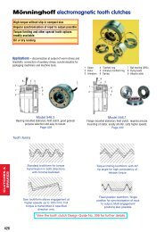
Principle of operation<br />
INTORQ <strong>BFK458</strong> spring-applied brake<br />
Brake module E + rotor + hub + flange<br />
Brake module N + rotor + hub<br />
6<br />
1<br />
5<br />
7<br />
2<br />
8<br />
1 = Armature plate<br />
2 = Compression springs<br />
3 = Rotor<br />
4 = Hub<br />
5 = Shaft<br />
6 = Flange<br />
7 = Stator<br />
8 = Torque adjustment ring<br />
9 = Sleeve bolts<br />
s lü = Air gap<br />
1<br />
3<br />
9<br />
4<br />
4<br />
3<br />
9<br />
2<br />
s lü<br />
7<br />
s lü<br />
INTORQ <strong>BFK458</strong> spring-applied brakes are single-disc brakes<br />
with two friction surfaces. When a de-energised, several<br />
compression springs are used to generate the braking<br />
torque through friction locking. The brake is released<br />
electromagnetically. During the braking procedure, the rotor<br />
(3), which can be shifted axially on the hub (4), is pressed<br />
against the counter friction face (6) via the armature plate<br />
(1), by means of the compression springs (2). When the<br />
brakes are applied, an air gap s lü is present between the<br />
armature plate and the stator (7). The stator's coil is<br />
energised with DC voltage in order to release the brake.<br />
The resulting magnetic flux works against the spring force to<br />
draw the armature plate to the stator. This releases the rotor<br />
from the spring force and allows it to rotate freely. Brake<br />
module E supports the use of the torque adjustment ring (8)<br />
to reduce the braking torque.<br />
<strong>Industrial</strong> trucks are fitted with spring-applied brakes on the<br />
travel motor and with electromagnetic load wheel brakes.<br />
www.<strong>Industrial</strong><strong>Clutch</strong>.com<br />
7
INTORQ I <strong>BFK458</strong> spring-applied brake I en 5/2008<br />
Example applications<br />
INTORQ <strong>BFK458</strong> spring-applied brake<br />
Curtain up for INTORQ brakes<br />
A silenced version of the double spring-applied brake is used<br />
in the theatre as a redundant braking system.<br />
INTORQ opens and closes gates and doors<br />
Spring-applied brakes with manual release monitoring via<br />
microswitches and electromagnetic clutches ensure safe<br />
operation of door drives and automatic doors.<br />
Rotate, lift, move – whenever cranes are in motion,<br />
INTORQ spring-applied brakes are never far away<br />
Corrosion resistant designs and various sealing variants for<br />
spring-applied brakes in cranes.<br />
8<br />
www.<strong>Industrial</strong><strong>Clutch</strong>.com
INTORQ I <strong>BFK458</strong> spring-applied brake I en 5/2008<br />
Technical data<br />
Braking torques<br />
Depending on the individual application, the graduated<br />
torques listed in the tables below are available. A pole shim<br />
(brass film) must be placed between the stator and the<br />
armature plate if you want to achieve short operating times<br />
with low torques.<br />
Size 06 08 10 12 14 16 18 20 25<br />
80 E<br />
1,5 E 3,5 N/E 25 N/E 35 N/E 65 N/E 115 N/E 175 N/E<br />
2 N/E 4 E 7 N/E 14 N/E 35 N 45 N/E 80 N/E 145 N/E 220 N<br />
2,5 N/E 5 N/E 9 N/E 18 N/E 40 N/E 55 N/E 100 N/E 170 N/E 265 N/E<br />
3 N/E 6 N/E 11 N/E 23 N/E 45 N/E 60 N/E 115 N/E 200 N/E 300 N/E<br />
Characteristic torques [Nm],<br />
related to the relative speed<br />
∆n = 100 rpm<br />
3,5 N/E 7 N/E 14 N/E 27 N/E 55 N/E 70 N/E 130 N/E 230 N/E 350 N/E<br />
4 N/E 8 N/E 16 N/E 32 N/E 60 N/E 80 N/E 150 N/E 260 N/E 400 N/E<br />
4,5 N/E 9 N/E 18 N/E 36 N/E 65 N/E 90 N/E 165 N/E 290 N/E 445 N/E<br />
5 E 10 E 20 E 40 E 75 N/E 100 N/E 185 N/E 315 N/E 490 N/E<br />
5,5 E 11 E 23 N/E 46 N/E 80 N/E 105 N/E 200 N/E 345 N/E 530 N/E<br />
6 N/E 12 N/E 125 N/E 235 N/E 400 N/E 600 N/E<br />
| N ... Braking torque for design N (without torque adjustment ring)<br />
| E ... Braking torque for design E (with torque adjustment ring)<br />
Service brake<br />
(s lümax approximately 2.5 x s lü )<br />
Standard braking torque<br />
Holding brake with emergency stop<br />
(s lümax approximately 1.5 x s lü )<br />
NEW: LongLife <strong>BFK458</strong>-L<br />
Designs<br />
| Sizes 06, 08, 10, 12<br />
| Stator in line with the “N design”<br />
| Braking torques up to standard torque available<br />
according to the catalogue<br />
| Low braking torques also configurable without pole<br />
shim<br />
| Microswitches not configurable<br />
| Rear face bores and built-on rear face accessories<br />
not possible<br />
Brake module E, reduced braking torque<br />
The braking torque on brake module E can be reduced<br />
using the torque adjustment ring located in the stator.<br />
The torque adjustment ring can be unscrewed to a<br />
maximum dimension of h 1max (see table on page 10).<br />
It should be noted that the engagement and disengagement<br />
times change in accordance with the braking torque. Torque<br />
reduction is independent of the rated torque used.<br />
Size 06 08 10 12 14 16 18 20 25<br />
Torque reduction<br />
per detent position [Nm] 0.2 0.35 0.8 1.3 1.7 1.6 3.6 5.6 6.2<br />
www.<strong>Industrial</strong><strong>Clutch</strong>.com<br />
9
INTORQ I <strong>BFK458</strong> spring-applied brake I en 5/2008<br />
Technical data<br />
Brake module E/N + flange + manual release<br />
slü<br />
Thickness of friction plate: 1.5 mm<br />
(sizes 06-16)<br />
Size b d J7 1) d H7 2) d 1 d 2 d H7 3 d 5 d 6j7 d 7 d 8 d H8 9 d 10 d 11 d 12 d 13 d 3) 14 d 3) 15 d 16 di da<br />
spec. standard<br />
06 88 10 10/11/12/14/15 3xM4 72 25 91 87 87 52 24 31 8 13 9.6 4xM4 37.7 3x4.5 40 60<br />
08 106.5 10 11/12/14/15/20 3xM5 90 32 109 105 105 60 26 41 8 13 9.6 4xM5 49 3x5.5 47 77<br />
10 132 10 11/12/14/15/20 3xM6 112 42 134 130 130 68 35 45 10 13 12 4xM5 54 3x6.6 66 95<br />
12 152 14 20/25 3xM6 132 50 155 150 150 82 40 52 10 13 12 4xM5 64 3x6.6 70 115<br />
14 169 14 20/25/30 3xM8 145 60 169 165 165 92 52 55 12 24 14 4xM6 75 3x9 80 124<br />
16 194.5 15 25/30/35/38* 3xM8 170 68 195 190 190 102 52 70 12 24 14 4xM6 85 3x9 104 149<br />
18 222 20 30/35/40/45 6xM8 196 75 222 217 217 116 62 77 14 24 15.5 4xM8 95 4x9 4) 129 174<br />
20 258 25 35/40/45/50 6xM10 230 85 259 254 254 135 72 90 14 24 16.5 4xM10 110 4x11 4) 148 206<br />
25 302 30 40/45/50/55/60/65/70* 6xM10 278 115 307 302 302 165 85 120 16 24 18.4 4xM10 140 6x11 199 254<br />
| 1) pre-drilled without keyway<br />
| 2) Standard keyway in accordance with DIN 6885/1 P9, selection of the shaft diameter<br />
depending on the type of loading (see Operating Instructions)<br />
| * Ø 38 and Ø 70 mm, keyway in accordance with DIN 6885/3 P9<br />
| 3) Bores are made on customer request for sizes 06–12<br />
| 4) The thread in the mounting surface is offset by 30° in relation to the centre axle of the<br />
manual release lever<br />
| Dimensions in mm<br />
Size h h 1 h 1 h 2 h 3 h 4 h 5 h 7) 5 h 6 h 7 h 8 h 9 l l 5) 1 s lü a b 6)<br />
min. max. standard max.<br />
06 36.3 39.3 43.25 1 6 15.8 107 – 54.5 23 32.8 56.3 18 400 0.2 25° 12°<br />
08 42.8 46.8 50.8 1.5 7 16.3 116 – 63 23 41.3 65 20 400 0.2 25° 10°<br />
10 48.4 52.4 55.9 2 9 27.4 132 – 73.8 23 42.4 77.8 20 400 0.2 25° 9°<br />
12 54.9 58.9 67.53 2 9 29.4 161 – 85 23 47.4 88.5 25 400 0.3 25° 10°<br />
14 66.3 71.3 77.3 2 11 33 195 – 98 32 50 101.5 30 400 0.3 25° 9°<br />
16 72.5 77.5 85.5 2.25 11 37.5 240 – 113 32 53.5 116 30 600 0.3 25° 10°<br />
18 83.1 89.1 97.09 2.75 11 41.1 279 394 124 32 59.1 128.5 35 600 0.4 25° 9°<br />
20 97.6 104.6 114.6 3.5 11 47.6 319 416 146 32 68.6 149.5 40 600 0.4 25° 10°<br />
25 106.7 115.7 127.7 4.5 12.5 57.7 445 501 170 32 88.7 175.5 50 600 0.5 25° 10°<br />
| 5) Length of the connecting cable<br />
| Recommended ISO shaft tolerances: up to Ø 50 mm = k6<br />
| 6) Manual release angle tolerance +3°<br />
over Ø 50 mm = m6<br />
| 7) Recommended lever length for 1.5 M K<br />
10<br />
www.<strong>Industrial</strong><strong>Clutch</strong>.com
INTORQ I <strong>BFK458</strong> spring-applied brake I en 5/2008<br />
Technical data<br />
Brake module N + centring flange<br />
Brake suitable for mounting a speed or angle<br />
sensor<br />
Size h h 1 h 2 d H7 d 1) 1 d 2 d 3 d 5) 4 d H7 5 d h7 6 d H7 7 d 8 di da l l 2) 1 l 2 s lü<br />
max.<br />
06 42.3 36.3 7 15 3xM4 72 37.7 4xM4 25 95 40 98 40 60 18 400 2 0.2<br />
08 49.8 42.8 8.5 20 3xM5 90 49 4xM5 32 115 50 116 47 77 20 400 2 0.2<br />
10 57.4 48.4 11 20 3xM6 112 54 4xM5 42 140 60 141 66 95 20 400 2 0.2<br />
12 63.9 54.9 11 25 3xM6 132 64 4xM5 50 162 60 165 70 115 25 400 2 0.3<br />
14 76.5 65.5 13 30 3xM8 145 75 4xM6 60 177 80 181 80 124 30 400 2 0.3<br />
16 83.5 72.5 13.25 38 4) 3xM8 170 85 4xM6 68 204 85 206 104 149 30 600 2 0.3<br />
18 94.1 83.1 13.75 45 6xM8 196 95 4xM8 75 233 90 237 129 174 35 600 2 0.4<br />
20 108.6 97.6 14.5 50 6xM10 230 110 4xM10 85 271 90 274 148 206 40 600 2 0.4<br />
25 118.2 106.7 17 70 4) 6xM10 278 140 4xM10 115 322 120 324 199 254 50 600 2 0.5<br />
| 1) Use DIN 6912 fixing screws<br />
| 2) Cable length<br />
| 3) Manual release can be mounted as an option, as shown on right of page 10<br />
| 4) Keyway in accordance with DIN 6885/3-P9<br />
| 5) Bores are made on customer request for sizes 06–12<br />
| Dimensions in mm<br />
www.<strong>Industrial</strong><strong>Clutch</strong>.com<br />
11
INTORQ I <strong>BFK458</strong> spring-applied brake I en 5/2008<br />
Technical data<br />
Brake module N + connection flange + brake module N<br />
Double brake (double braking torque) as redundant<br />
braking system, suitable for use in stage machinery and<br />
many other areas of application<br />
Size d H7 d 1 d 2 d H7 5 d 6j7 di da H h h 1 h 2 h 3 l l 1) 1 l 2 s lü<br />
max.<br />
06 15 3xM4 72 25 87 40 60 84.6 36.3 12 1 48.3 18 400 8.7 0.2<br />
08 20 3xM5 90 32 105 47 77 97.6 42.8 12 1.5 54.8 20 400 9.8 0.2<br />
10 20 3xM6 112 42 130 66 95 109.8 48.4 13 2 61.4 20 400 12.7 0.2<br />
12 25 3xM6 132 50 150 70 115 125.8 54.9 16 2 70.9 25 400 13.1 0.3<br />
14 30 3xM8 145 60 165 80 124 148 65.5 17 2 82.5 30 400 13.1 0.3<br />
16 382) 3xM8 170 68 190 104 149 165 72.5 20 2.25 92.5 30 600 16.4 0.3<br />
18 45 6xM8 196 75 217 129 174 186.2 83.1 20 2.75 103.1 35 600 17.5 0.4<br />
20 50 6xM10 230 85 254 148 206 215.2 97.6 20 3.5 117.6 40 600 17.8 0.4<br />
25 70 6xM10 278 115 302 199 254 238.4 106.7 25 4.5 130.7 50 600 21.5 0.5<br />
| 1) Cable length<br />
| 2) Keyway in accordance with DIN 6885/3-P9<br />
| Manual release as an option<br />
| Dimensions in mm<br />
Noise-reduced designs<br />
The noise reduction required in many applications can be<br />
achieved in two ways:<br />
1. Impact-noise-reduced armature plate<br />
The brake's operating noise can be minimised using special<br />
damping elements, which are installed between the pole<br />
face and the armature plate as shock absorbers.<br />
2. Noise-reduced aluminium rotor<br />
Rattling noises, which can occur in the rotor/hub connection,<br />
for example, during frequency inverter operation, or as<br />
a result of load alternation, or non-constant speeds, are<br />
reduced by using a rotor with a plastic sleeve.<br />
The noise-reduced aluminium rotor is for the LongLife design<br />
obligatory.<br />
12<br />
www.<strong>Industrial</strong><strong>Clutch</strong>.com
INTORQ I <strong>BFK458</strong> spring-applied brake I en 5/2008<br />
Technical data<br />
Rated data<br />
Size P 1) s lü max s lü max max. min. 2) J plastic rotor J aluminium rotor Mass of<br />
[20 °C] service brake holding brake adjustment rotor thickness stator<br />
[W] [mm] [mm] [mm] [mm] [kgcm 2 ] [kgcm 2 ] assy [kg]<br />
06 20 0.5 0.3 1.5 4.5 0.11 0.15 0.75<br />
08 25 0.5 0.3 1.5 5.5 0.34 0.61 1.2<br />
10 30 0.5 0.3 1.5 7.5 – 2.0 2.1<br />
12 40 0.75 0.45 2.0 8.0 – 4.5 3.5<br />
14 50 0.75 0.45 2.5 7.5 – 6.3 5.2<br />
16 55 0.75 0.45 3.5 8.0 – 15 7.9<br />
18 85 1.0 0.6 3.0 10.0 – 29 12<br />
20 100 1.0 0.6 4.0 12.0 – 73 19.3<br />
25 110 1.25 0.75 4.5 15.5 – 200 29.1<br />
| 1) Coil power at 20°C in W, possible deviation up to +10%, depending on supply voltage selected<br />
| 2) The friction lining is dimensioned so that the brake can be readjusted at least five times.<br />
Braking torques, depending on speed and permissible<br />
limit speeds<br />
Size Average braking torque at ∆ n0 [rpm] max. speed<br />
braking torque on braking [%] ∆n 0max<br />
off ∆n 0 to a standstill<br />
[%] 1500 3000 max. [rpm]<br />
06 100 87 80 65 12400<br />
08 100 85 78 66 10100<br />
10 100 83 76 66 8300<br />
12 100 81 74 66 6700<br />
14 100 80 73 67 6000<br />
16 100 79 72 66 5300<br />
18 100 77 70 66 4400<br />
20 100 75 68 66 3700<br />
25 100 73 66 66 3000<br />
As speed increases, so does wear.<br />
www.<strong>Industrial</strong><strong>Clutch</strong>.com<br />
13
INTORQ I <strong>BFK458</strong> spring-applied brake I en 5/2008<br />
Technical data<br />
Operating times<br />
The listed operating times apply to DC switching with rated<br />
air gap s lü and a warm coil. The times are mean values which<br />
may vary depending on the method of rectification<br />
and the air gap s lü . The engagement time t 1 is approximately<br />
10 times higher for AC switching than for DC switching.<br />
Torque time characteristic, dependent on<br />
excitation voltage<br />
Characteristic torque<br />
Time<br />
t 11 = Delay<br />
time<br />
t 12 = Rise time of<br />
braking torque<br />
t 1 = Engagement time<br />
t 2 = Disengagement time<br />
t 3 = Slipping time<br />
AC switching<br />
DC switching<br />
Excitation<br />
Time<br />
Size Braking torque Maximum permissible Transitional- Switching times [ms] 2)<br />
rating at switching energy at switching at s lüRated<br />
∆n = 100 rpm single switching operation frequency<br />
M 1) K Q E S hü Connection on the DC side Disconnect<br />
[Nm] [J] [h -1 ] t 11 t 12 t 1 t 2<br />
06 4 3000 79 15 13 28 45<br />
08 8 7500 50 15 16 31 57<br />
10 16 12000 40 28 19 47 76<br />
12 32 24000 30 28 25 53 115<br />
14 60 30000 28 17 25 42 210<br />
16 80 36000 27 27 30 57 220<br />
18 150 60000 20 33 45 78 270<br />
20 260 80000 19 65 100 165 340<br />
25 400 120000 15 110 120 230 390<br />
| 1) Minimum braking torque for run-in friction pairs<br />
| 2) Operating times valid for 205 V DC coils<br />
14<br />
www.<strong>Industrial</strong><strong>Clutch</strong>.com
INTORQ I <strong>BFK458</strong> spring-applied brake I en 5/2008<br />
Technical data<br />
Service life and wear<br />
The brake has to be adjusted when s lümax is reached. The<br />
friction energy to be withstood up to this point is dependent<br />
on a number of factors: in particular, the inertias to be braked,<br />
the braking speed, the operating frequency and the<br />
resulting temperature on the friction surfaces. For this reason,<br />
no universal value for all operating conditions can be<br />
given in respect of the amount of friction energy that can<br />
be handled before adjustment is required.<br />
In addition, increased wear should be expected with<br />
vertical mounting.<br />
The <strong>BFK458</strong> can be adjusted when the maximum permissible<br />
working air gap is reached (s lümax ). The dimensioning of<br />
the friction lining allows adjustment to be carried out at<br />
least five times.<br />
Where the amount of friction energy per switching operation<br />
is low, the brake's mechanical components can impose<br />
limitations in terms of service life. In particular, the<br />
rotor/hub connection, springs, armature plate and sleeves<br />
are subject to operational wear. The expected service life of<br />
the standard design is around 1 million load alternations.<br />
Solutions that are optimised in terms of service life are<br />
available in cases where a longer service life is required<br />
(consult the manufacturer).<br />
Maintenance<br />
Brakes are components which are subject to a great deal of<br />
wear. When installing the brake, it must be ensured that it<br />
can be easily accessed for inspection and maintenance<br />
purposes. Intervals between inspections should be set in<br />
accordance with the expected service life and load. For<br />
more information, please see the Operating Instructions.<br />
Permissible friction energy Q zul depending on<br />
operating frequency S h<br />
Qzul in [J]<br />
10 5<br />
10 4<br />
10 3<br />
25<br />
16<br />
10<br />
20<br />
18<br />
14 12<br />
08<br />
06<br />
Sizes<br />
LongLife Spring-applied brake INTORQ <strong>BFK458</strong>-L<br />
Guaranteed performance data<br />
| Guaranteed service life of brake mechanism:<br />
10x10 6 repetitive cycles of operation<br />
15x10 6 reversing cycles of operation<br />
| The brake warranty covers either two years or the<br />
guaranteed number of cycles – whichever is reached first.<br />
| The scope of the warranty in the event of premature<br />
failure covers replacement of the brake, including a<br />
flat-rate replacement fee.<br />
10 2<br />
10<br />
1 10 10 2 10 3 10 4<br />
S h [h -1 ]<br />
www.<strong>Industrial</strong><strong>Clutch</strong>.com<br />
15
INTORQ I <strong>BFK458</strong> spring-applied brake I en 5/2008<br />
Accessories<br />
Manual release<br />
The manual release is used to release the brake by hand and<br />
can be retrofitted. The manual release springs back to its<br />
base position (0 setting) automatically after operation. The<br />
release screws are carried in ball joints and are only tensioned.<br />
The air gap "s" is the distance between the armature<br />
plate (1) and the washer (15). The dimension "s" must be<br />
maintained when installing the manual release.<br />
Size s + 0.1 lü<br />
- 0.05<br />
s +0.1<br />
[mm] [mm]<br />
06<br />
08 0.2 1<br />
10<br />
12<br />
14 0.3 1.5<br />
16<br />
s lü<br />
18<br />
20<br />
0.4 2<br />
25 0.5 2.5<br />
Manual release<br />
Flange<br />
A flange can be used if no suitable counter friction face is<br />
available. The flange can also be fitted with the seal.<br />
Friction plate<br />
A friction plate may be supplied for sizes 06 up to and including<br />
16. This should be used if the counter face is smooth<br />
and machined, but is not suitable as a friction surface. Combination<br />
with a cover ring is provided.<br />
Flange<br />
Friction plate<br />
(sizes 06 – 16)<br />
16<br />
www.<strong>Industrial</strong><strong>Clutch</strong>.com
INTORQ I <strong>BFK458</strong> spring-applied brake I en 5/2008<br />
Accessories<br />
Centring flange (tacho brake)<br />
Brake module N combined with a centring flange is suitable<br />
for mounting a tachogenerator.<br />
Connection flange (double brake)<br />
The connection flange can be used to adapt a second brake<br />
module to brake module N; the resulting double brake is suitable<br />
for use in stage machinery or other applications with<br />
increased safety requirements.<br />
Centring flange<br />
Connection flange<br />
Seal<br />
Seal<br />
To a large extent, the seal prevents the exit or ingress of<br />
dust, humidity, dirt, etc., out of or into the braking area. The<br />
seal is inserted into the groove on the stator. If no suitable<br />
groove is available on the counter friction face, we recommend<br />
the use of a flange.<br />
www.<strong>Industrial</strong><strong>Clutch</strong>.com<br />
17
INTORQ I <strong>BFK458</strong> spring-applied brake I en 5/2008<br />
Accessories<br />
Brake cover<br />
Brake module E, N + cover = encapsulated design<br />
A cover can be mounted onto brake module E and brake<br />
module N as an option, to protect the brake from water and<br />
dust (enclosure to IP 65). This design is not available in conjunction<br />
with manual release.<br />
Size d 1 d 2 d H8 3 d 4 d 5 h h 1 h 2 h 1) 3<br />
06 135 120 98 4x5.5 M16x1.5 55 28 16.5 3<br />
08 155 142 118 4x5.5 M20x1.5 61 34 20 3<br />
10 185 166 143 4x5.5 M20x1.5 72 39 21 3<br />
12 205 192 163 4x6.6 M20x1.5 82 42 23 3<br />
14 225 212 183 4x6.6 M20x1.5 92 51 24 3<br />
16 250 236 208 4x6.6 M20x1.5 98 52 25 3<br />
18 285 268 238 4x6.6 M20x1.5 115 60 29 3<br />
20 330 314 283 4x9 M20x1.5 131 69 35 3<br />
25 390 368 328 4x9 M20x1.5 142 78 40 3<br />
| 1) Recommended recess length on motor endshield<br />
18<br />
www.<strong>Industrial</strong><strong>Clutch</strong>.com
INTORQ I <strong>BFK458</strong> spring-applied brake I en 5/2008<br />
Accessories<br />
Microswitch<br />
The brake can be fitted with a microswitch for the purpose<br />
of monitoring the release or wear. The microswitch can be<br />
built into the circuit as an NC contact or an NO contact.<br />
For the LongLife design the microswitch is not available.<br />
Mounting the microswitch onto brake module E<br />
Dimensions<br />
Size 12 14 16 18 20 25<br />
Dimension x 13 11.5 11 7 * *<br />
Overall radius r 80.5 88.5 99 112.5 * 155<br />
| * no projection<br />
| Dimensions in mm<br />
Microswitch for manual release monitoring<br />
Gate drives, for instance, are provided with brakes with<br />
manual release, and a microswitch for monitoring the<br />
manual release. In this case, the manual release must make<br />
it possible to move the gate to the desired position in<br />
manual operation, e.g. using a crank. This manual operation<br />
has to be detected via a microswitch, whose switching signal<br />
must be combined with the motor control, so that the<br />
motor can be prevented from starting (thus also preventing<br />
any possible injury to the operator). The microswitch for<br />
manual release monitoring is a built-on option.<br />
The fixing bracket is screwed onto the magnet housing or<br />
stator via the bores on the rear face. The fixing bracket enables<br />
a microswitch to be fastened to it. The two directions of<br />
release, towards and away from the motor, can be implemented<br />
by using different fixing brackets and microswitch<br />
settings.<br />
www.<strong>Industrial</strong><strong>Clutch</strong>.com<br />
19
INTORQ I <strong>BFK458</strong> spring-applied brake I en 5/2008<br />
Accessories<br />
Terminal box<br />
The connecting cables can easily be integrated into higherlevel<br />
controls via the terminal box (brake sizes 12-25) in<br />
order to support different wiring options (three<br />
inputs/outputs). 2/4-pole terminal strips, half-wave and<br />
bridge rectifiers and a microswitch connection can be integrated<br />
into the terminal box.<br />
The terminal box is mounted onto the spring-applied brake<br />
using a fixing bracket and screws, as shown in the illustration.<br />
You can select the mounting angle according<br />
to your requirements by using the assembly kit.<br />
The terminal box is shown<br />
offset by 30°.<br />
Size 12 14 16 18 20 25<br />
b -5 5.5 12.5 23 37.5 45.5<br />
h 122 130 142 155 174 198<br />
r 126 134 146 158.5 177 201<br />
| Dimensions in mm<br />
20<br />
www.<strong>Industrial</strong><strong>Clutch</strong>.com
INTORQ I <strong>BFK458</strong> spring-applied brake I en 5/2008<br />
Accessories<br />
Bridge rectifiers and half-wave rectifiers<br />
Type code B E G – 5 6 1 – 440<br />
Brake<br />
Electronic<br />
Rectifier<br />
1 Bridge rectifier<br />
2 Half-wave rectifier<br />
5 Bridge rectifier/half-wave rectifier<br />
4-pole<br />
6-pole<br />
1-Mounting position horizontal<br />
2-Mounting position vertical<br />
3-Mounting position horizontal with snap-in stud<br />
440 440 V voltage<br />
INTORQ 14.198.00.0ò universal spark suppressor<br />
The universal spark suppressor limits the induced voltage<br />
arising when inductive direct current consumers are switched<br />
off on the DC side. These induced voltages can damage<br />
coils and switches. VDE 0580 therefore requires that, in<br />
order to avoid impermissibly<br />
high switch off voltages and overvoltages, suitable protective<br />
measures must be provided by the user. The universal<br />
spark suppressor is available in 4 versions for the following<br />
voltage ranges:<br />
INTORQ Coil Max. mains Max. coil Capacitor b 1 b 2 d e h l 1 l 2 m<br />
voltage voltage power voltage approx. approx. approx. [g]<br />
14.198.00.01 24 V – 50 V 60 V ~ 110 W 250 V- 8.5 12.5 0.7 22.5 18.5 26.5 25 7<br />
14.198.00.02 50 V – 120 V 250 V ~ 110 W 630 V- 15 21 0.7 37.5 26 41.5 20 22<br />
14.198.00.03 120 V – 200 V 400 V ~ 110 W 1000 V- 13 20 0.7 37.5 24 41.5 15 17<br />
14.198.00.04 200 V – 250 V 555 V ~ 110 W 1000 V- 13 20 0.7 37.5 24 41.5 15 10<br />
Dimensions<br />
Wiring example<br />
Parallel to contact<br />
Parallel to coil<br />
www.<strong>Industrial</strong><strong>Clutch</strong>.com<br />
21
INTORQ I <strong>BFK458</strong> spring-applied brake I en 5/2008<br />
Accessories<br />
4-pole bridge rectifier and 4-pole half-wave rectifier<br />
Dimensions<br />
BEG-142/143-270<br />
BEG-242/243-555<br />
BEG-142/143-270<br />
4-pole bridge rectifier<br />
BEG-142-270<br />
BEG-143-270<br />
Application area<br />
Current supply for spring-applied brakes from AC mains (normal<br />
excitation).<br />
Example: 205 V coil on 230 V mains<br />
Technical data<br />
Max. mains voltage 270 V~<br />
Max. DC current at 60°C 1.0 A<br />
Max. ambient temperature 80°C<br />
The rectifiers are protected against overvoltage by input and<br />
output varistors.<br />
4-pole half-wave rectifier<br />
BEG-242-555<br />
BEG-243-555<br />
Application area<br />
Current supply for spring-applied brakes from AC mains (normal<br />
excitation).<br />
Example: 180 V coil on 400 V mains<br />
Technical data<br />
Max. mains voltage 555 V~<br />
Max. DC current at 60°C 1.0 A<br />
Max. ambient temperature 80°C<br />
The rectifiers are protected against overvoltage by input and<br />
output varistors.<br />
Ug = U ~ =<br />
230 V ~ = 205 V<br />
1.11 1.11<br />
Ug = U ~ =<br />
400 V ~ = 180 V<br />
2.22 2.22<br />
22<br />
www.<strong>Industrial</strong><strong>Clutch</strong>.com
INTORQ I <strong>BFK458</strong> spring-applied brake I en 5/2008<br />
Accessories<br />
6-pole bridge rectifier<br />
Dimensions<br />
BEG-162-270<br />
BEG-161-270<br />
BEG-162-270<br />
BEG-161-270<br />
6-pole bridge rectifier<br />
BEG-162-270<br />
BEG-161-270<br />
Application area<br />
Current supply for spring-applied brakes from AC mains<br />
(normal excitation).<br />
Example: 205 V coil on 230 V mains<br />
Technical data<br />
Max. mains voltage 270 V~<br />
Max. DC current at 60°C 0.75 A<br />
Max. ambient temperature 80°C<br />
The rectifiers are protected against overvoltage by input and<br />
output varistors.<br />
BEG-162-270/161-270/262-460/261-460 rectifiers also<br />
contain the spark suppressors required by VDE 0580<br />
Section 26.<br />
Ug = U ~ =<br />
230 V ~ = 205 V<br />
1.11 1.11<br />
www.<strong>Industrial</strong><strong>Clutch</strong>.com<br />
23
INTORQ I <strong>BFK458</strong> spring-applied brake I en 5/2008<br />
Accessories<br />
6-pole half-wave rectifier<br />
Dimensions<br />
BEG-262-460<br />
BEG-262-555<br />
BEG-261-460<br />
BEG-261-555<br />
BEG-262-460<br />
BEG-261-460<br />
6-pole half-wave rectifier<br />
BEG-262-460<br />
BEG-261-460<br />
BEG-262-555<br />
BEG-261-555<br />
Application area<br />
Current supply for spring-applied brakes from AC mains<br />
(normal excitation).<br />
Example: 180 V coil on 400 V mains<br />
Technical data<br />
Max. mains voltage 555 V~ / 460 V~<br />
Max. DC current at 60°C 0.75 A<br />
Max. ambient temperature 80°C<br />
The rectifiers are protected against overvoltage by input and<br />
output varistors. BEG-162-270/161-270/262-460/<br />
261-460 rectifiers also contain the spark suppressor required<br />
by VDE 0580 Section 26.<br />
Ug = U ~ =<br />
400 V ~ = 180 V<br />
2.22 2.22<br />
24<br />
www.<strong>Industrial</strong><strong>Clutch</strong>.com
INTORQ I <strong>BFK458</strong> spring-applied brake I en 5/2008<br />
Accessories<br />
Fixing options<br />
4-pole rectifier<br />
Brake<br />
Guide<br />
or<br />
or<br />
Snap-in stud<br />
Bore Ø 4.3<br />
1 to 3 mm thick<br />
Fixing options<br />
6-pole rectifier<br />
Guide<br />
www.<strong>Industrial</strong><strong>Clutch</strong>.com<br />
25
INTORQ I <strong>BFK458</strong> spring-applied brake I en 5/2008<br />
Accessories<br />
Connection diagrams<br />
DC switching<br />
Bridge rectifier<br />
BEG-162-270<br />
BEG-161-270<br />
half-wave rectifier<br />
BEG-262-460<br />
BEG-261-460<br />
Also for<br />
star connection<br />
with half-wave rectifier<br />
BEG-262-460<br />
BEG-261-460<br />
Coil 103 V<br />
180 V<br />
AC switching<br />
Also for<br />
star connection<br />
Bridge rectifier<br />
BEG-142-270<br />
BEG-143-270<br />
Also for<br />
star connection<br />
half-wave rectifier<br />
BEG-242-555<br />
BEG-243-555<br />
with half-wave rectifier<br />
BEG-242-555<br />
BEG-243-555<br />
Coil 103 V<br />
180 V<br />
AC switching parallel to the motor<br />
Bridge rectifier<br />
BEG-142-270<br />
BEG-143-270<br />
half-wave rectifier<br />
BEG-242-555<br />
BEG-243-555<br />
Also for<br />
star connection<br />
with half-wave rectifier<br />
BEG-242-555<br />
BEG-243-555<br />
Coil 103 V<br />
180 V<br />
26<br />
www.<strong>Industrial</strong><strong>Clutch</strong>.com
INTORQ I <strong>BFK458</strong> spring-applied brake I en 5/2008<br />
Accessories<br />
Mains voltage selection table<br />
Rectifier type and rated coil voltage for<br />
mains voltage<br />
AC Rectifier Rectifier type Spark suppressor Rectifier type Coil<br />
voltage 4-pole 6-pole rated<br />
voltage<br />
[V] 1 A at 60°C INTORQ 0.75 A at 60°C [V]<br />
42 V Half-wave BEG-243/242-555 14.198.00.01 BEG-262/261-460 20 V<br />
48 V Bridge BEG-142/143-270 14.198.00.01 BEG-162/161-270 42 V<br />
Half-wave BEG-243/242-555 14.198.00.01 BEG-262/261-460 20 V<br />
110 V Bridge BEG-142/143-270 14.198.00.02 BEG-162/161-270 103 V<br />
220 V Bridge BEG-142/143-270 14.198.00.04 BEG-162/161-270 205 V<br />
Half-wave BEG-243/242-555 14.198.00.02 BEG-262/261-460 103 V<br />
230 V Bridge BEG-142/143-270 14.198.00.04 BEG-162/161-270 205 V<br />
Half-wave BEG-243/242-555 14.198.00.02 BEG-262/261-460 103 V<br />
240 V Bridge BEG-142/143-270 14.198.00.04 BEG-162/161-270 215 V<br />
Half-wave BEG-243/242-555 14.198.00.02 BEG-262/261-460 103 V<br />
255 V Bridge BEG-142/143-270 14.198.00.04 BEG-162/161-270 225 V<br />
277 V Half-wave BEG-243/242-555 14.198.00.03 BEG-262/261-460 127 V<br />
290 V Half-wave BEG-243/242-555 14.198.00.03 BEG-262/261-460 127 V<br />
380 V Half-wave BEG-243/242-555 14.198.00.03 BEG-262/261-460 180 V<br />
400 V Half-wave BEG-243/242-555 14.198.00.03 BEG-262/261-460 180 V<br />
415 V Half-wave BEG-243/242-555 14.198.00.03 BEG-262/261-460 180 V<br />
420 V Half-wave BEG-243/242-555 14.198.00.03 BEG-262/261-460 180 V<br />
440 V Half-wave BEG-243/242-555 14.198.00.04 BEG-262/261-460 205 V<br />
460 V Half-wave BEG-243/242-555 14.198.00.04 BEG-262/261-460 205 V<br />
480 V Half-wave BEG-243/242-555 14.198.00.04 BEG-262/261-555* 215 V<br />
500 V Half-wave BEG-243/242-555 14.198.00.04 BEG-262/261-555* 225 V<br />
555 V Half-wave BEG-243/242-555 14.198.00.04 BEG-262/261-555* 250 V<br />
| * Spark suppressor without capacitor. For optimum interference suppression, we recommend<br />
the use of spark suppressor 14.198.00.04.<br />
Max. rated coil voltage: 250 V<br />
Standard coil rated voltages: 24, 96, 103, 170, 180, 190, 205 V<br />
www.<strong>Industrial</strong><strong>Clutch</strong>.com<br />
27
INTORQ I <strong>BFK458</strong> spring-applied brake I en 5/2008<br />
Dimensioning<br />
Basic information<br />
The size of a brake is largely determined by the required<br />
braking torque M erf . The inertias to be braked (moments of<br />
inertia), the relative speeds, the braking times and the operating<br />
frequencies also have to be considered in the calculations.<br />
Marginal conditions, such as ambient temperature,<br />
air humidity, dust and mounting position should be known.<br />
In the event of extreme/critical operating conditions, please<br />
consult the manufacturer. Selection takes place in accordance<br />
with VDI rule 2241.<br />
Friction surfaces must always be kept free of oil and<br />
grease.<br />
For explanations of the terms used in the calculation, please<br />
refer to the list of abbreviations on page 5.<br />
Safety factor<br />
To ensure the necessary transmission security even under<br />
extreme operating conditions, the calculated braking torque<br />
is multiplied by safety factor K, which depends on the operating<br />
conditions.<br />
K 2<br />
Load types<br />
In practice, the following load types mainly occur:<br />
M erf = (M a ± M L ) · K MK<br />
J L · ∆n0<br />
M erf = ( ± M L )· K MK<br />
t12<br />
9.55 · t 3<br />
(<br />
2 )<br />
+ M L = to be used when lowering a load, for example<br />
– M L = for normal braking<br />
Approximate determination of the required braking torque<br />
and the size<br />
If only the drive power to be transmitted is known, the required<br />
torque or braking torque can be determined as follows:<br />
M erf = 9550 P · K MK<br />
∆n0<br />
Thermal load<br />
For high operating frequencies and friction energy/switching<br />
cycle, the brake should be subject to thermal<br />
checking. The friction energy per switching cycle is calculated<br />
as follows:<br />
Q = J L · ∆n 2 0 ·<br />
M K<br />
182.5 M K ± M L<br />
M erf = M a · K M K<br />
M a =<br />
J L<br />
( )<br />
· ∆n0<br />
t 3 – t 12<br />
9.55 ·<br />
2<br />
J L<br />
( )<br />
· ∆n0<br />
M erf =<br />
t 3 – t 12<br />
9.55 ·<br />
2<br />
· K<br />
– M L = to be used when lowering a load, for example<br />
+ M L = for normal braking<br />
The permissible friction energy per switching cycle at a<br />
given operating frequency can be taken from the diagrams<br />
on page 14. If the friction energy per switching cycle is known,<br />
the permissible operating frequency can be taken from<br />
the diagrams mentioned above.<br />
Dynamic plus static load<br />
Most applications belong to this category, as in most cases<br />
there is not only a static torque but also a dynamic load.<br />
28<br />
www.<strong>Industrial</strong><strong>Clutch</strong>.com
INTORQ I <strong>BFK458</strong> spring-applied brake I en 5/2008<br />
Dimensioning<br />
Calculation example<br />
The following technical data is known:<br />
P = 3 kW<br />
∆n 0 = 1450 rpm<br />
J L = 0.52 kgm 2 total<br />
t 3 =2 s<br />
M L = 15 Nm<br />
S h = 6 operations/h<br />
Approximate determination of the required braking torque<br />
and the size:<br />
P<br />
M erf = 9550 · K<br />
∆n 0<br />
3<br />
M erf = 9550 · 2 = 40 N<br />
1450<br />
Assume INTORQ <strong>BFK458</strong>-14<br />
Calculating the required braking torque<br />
M erf =<br />
· ∆n0<br />
– ML<br />
( )<br />
t3 – t 12<br />
9.55 ·<br />
J L(<br />
2 )<br />
· K<br />
Thermal checking<br />
J<br />
Q = L · ∆n 2 0 M<br />
· K<br />
182.5 M K ± M L<br />
Q = 0.52 · 14502 60 · = 4792 J<br />
182.5 (60 + 15)<br />
Calculated switching energy Q = 4792 J/switching cycle<br />
The diagram on page 14 shows a permissible switching<br />
energy of 30,000 J for size 14 at S h = 6 h -1 .<br />
Q = 4792 J < Q zul = 30000 J<br />
Therefore, the brake has been selected correctly.<br />
Ordering example<br />
Brake type INTORQ <strong>BFK458</strong>-14E or design N (with or without<br />
torque adjustment ring) is required, with additional<br />
manual release and seal.<br />
Supply voltage 205 V = shaft diameter 25 mm.<br />
INTORQ <strong>BFK458</strong>-14E, 205 V =, d = 25 mm<br />
t 12 = 0.025 s (see page 14)<br />
( )<br />
0.52 · 1450<br />
M erf = –15 · 2 = 50 Nm<br />
9.55 · 2– 0.025<br />
2<br />
Therefore, INTORQ <strong>BFK458</strong>-14 is chosen.<br />
M K = 60 Nm > M erf = 50 Nm<br />
www.<strong>Industrial</strong><strong>Clutch</strong>.com<br />
29
INTORQ I <strong>BFK458</strong> spring-applied brake I en 5/2008<br />
Order form<br />
INTORQ <strong>BFK458</strong> spring-applied brake with accessories<br />
Recipient:<br />
INTORQ GmbH & Co. KG<br />
Wülmser Weg 5 · D-31855 Aerzen<br />
Fax +49 (0 )51 54 95 39 10<br />
Sender<br />
Company<br />
Street/PO Box<br />
Post code/City<br />
Delivery address*<br />
Customer no.<br />
Order no.<br />
Issuer<br />
Telephone<br />
Fax<br />
Invoice recipient*<br />
Date of delivery<br />
* Please specify, if different from sender. Date Signature<br />
INTORQ <strong>BFK458</strong>-òòò<br />
Complete stator<br />
Order quantity<br />
Number<br />
Size ò 06 ò 08 ò 10 ò 12 ò 14 ò 16 ò 18 ò 20 ò 25<br />
Type<br />
ò E (with torque adjustment ring)<br />
ò N (without torque adjustment ring)<br />
ò L (LongLife design)<br />
Voltage ò 24 V ò 96 V ò 103 V ò 170 V ò 180 V ò 190 V ò 205 V<br />
Braking torque<br />
Cable length<br />
Manual release<br />
Nm (see graduated torques)<br />
ò Standard<br />
mm (from 100 mm – 1000 mm in 100 mm steps,<br />
from 1000 mm – 2500 mm in 250 mm steps)<br />
ò Assembled<br />
Armature plate ò Standard ò Hard-chromium plated (from size 06) ò Noise-reduced*<br />
(O-ring design)<br />
ò With pole shim/brass film<br />
Microswitch*<br />
ò Operation monitoring (size 12 and above)<br />
ò Wear monitoring (size 12 and above)<br />
ò Manual release monitoring, direction of release away from motor (sizes 06-25)<br />
ò Manual release monitoring, direction of release towards motor (sizes 06-10)<br />
Terminal box* ò Mounted (from size 12)<br />
* not available for LongLife design<br />
30<br />
www.<strong>Industrial</strong><strong>Clutch</strong>.com
INTORQ I <strong>BFK458</strong> spring-applied brake I en 5/2008<br />
Order form<br />
Accessories<br />
Rotor ò Plastic ò Aluminium ò Silenced<br />
(only for size 06/08)<br />
(rotor with sleeve)<br />
Low wear rotor ò Aluminium ò Silenced<br />
(rotor with sleeve)<br />
for LongLife design<br />
obligatory<br />
Hub<br />
mm (for bore diameter, see Dimensions)<br />
Fixing<br />
screw set<br />
Manual release<br />
Terminal box*<br />
ò For mounting onto the flange<br />
ò For mounting onto the motor/friction plate<br />
ò For flange with through hole (up to and including size 16)<br />
ò For connection flange/double brake<br />
ò as mounting kit<br />
ò as mounting kit<br />
Flange ò Friction plate (up to and including size 16)<br />
ò Flange<br />
ò Tachometer flange<br />
ò Connection flange double brake<br />
Sealing<br />
ò Seal<br />
ò Shaft sealing ring (shaft diameter on request)<br />
ò Cap<br />
ò Brake cover<br />
Electrical accessories<br />
Bridge rectifier<br />
Half-wave rectifier<br />
Spark suppressor<br />
ò 4-pole without snap-in stud<br />
ò 4-pole with snap-in stud<br />
ò 6-pole vertical, integrated spark suppressor<br />
ò 6-pole horizontal, integrated spark suppressor<br />
ò 4-pole without snap-in stud<br />
ò 4-pole with snap-in stud<br />
ò 6-pole vertical, integrated spark suppressor<br />
ò 6-pole horizontal, integrated spark suppressor<br />
ò<br />
* not available for LongLife design<br />
www.<strong>Industrial</strong><strong>Clutch</strong>.com<br />
31