6v-12v-acu-charger-circuit-ayrlanabilir-current-control-mosfet - 320Volt
6v-12v-acu-charger-circuit-ayrlanabilir-current-control-mosfet - 320Volt
6v-12v-acu-charger-circuit-ayrlanabilir-current-control-mosfet - 320Volt

Create successful ePaper yourself
Turn your PDF publications into a flip-book with our unique Google optimized e-Paper software.
<strong>circuit</strong><br />
ideas<br />
Constant-Current<br />
Battery Charger<br />
s.c. dwivedi<br />
• Monoj Das<br />
There are many ways of battery<br />
charging but constant-<strong>current</strong><br />
charging, in particular, is a<br />
popular method for lead-acid and Ni-<br />
Cd batteries. In this <strong>circuit</strong>, the battery<br />
is charged with a constant <strong>current</strong> that<br />
is generally one-tenth of the battery<br />
capacity in ampere-hours. So for a<br />
4.5Ah battery, constant charging <strong>current</strong><br />
would be 450 mA.<br />
This battery <strong>charger</strong> has the following<br />
features:<br />
1. It can charge 6V, 9V and 12V batteries.<br />
Batteries rated at other voltages<br />
can be charged by changing the values<br />
of zener diodes ZD1 and ZD2.<br />
2. Constant <strong>current</strong> can be set as<br />
per the battery capacity by using a<br />
potmeter and multimeter in series with<br />
the battery.<br />
3. Once the battery is fully charged,<br />
it will attain certain voltage level (e.g.<br />
13.5-14.2V in the case of a 12V battery),<br />
give indication and the <strong>charger</strong> will<br />
switch off automatically. You need not<br />
remove the battery from the <strong>circuit</strong>.<br />
4. If the battery is discharged below<br />
a limit, it will give deep-discharge<br />
indication.<br />
5. Quiescent <strong>current</strong> is less than 5<br />
mA and mostly due to zeners.<br />
6. DC source voltage (V CC<br />
) ranges<br />
from 9V to 24V.<br />
7. The <strong>charger</strong> is short-<strong>circuit</strong> protected.<br />
D1 is a low-forward-drop schottky<br />
diode SB560 having peak reverse voltage<br />
(PRV) of 60V at 5A or a 1N5822<br />
diode having 40V PRV at 3A. Normally,<br />
the minimum DC source voltage<br />
should be ‘D1 drop+Full charged<br />
battery voltage+V DSS<br />
+ R2 drop,’ which<br />
is approximately ‘Full charged battery<br />
voltage+5V.’ For example, if we take<br />
full-charge voltage as 14V for a 12V<br />
battery, the source voltage should be<br />
14+5=19V.<br />
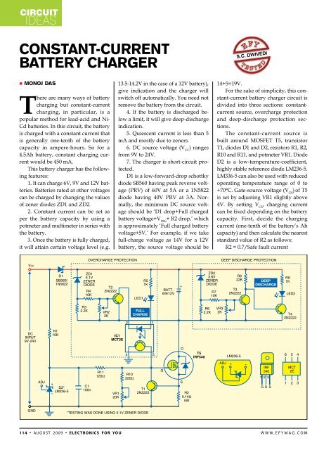
For the sake of simplicity, this constant-<strong>current</strong><br />
battery <strong>charger</strong> <strong>circuit</strong> is<br />
divided into three sections: constant<strong>current</strong><br />
source, overcharge protection<br />
and deep-discharge protection sections.<br />
The constant-<strong>current</strong> source is<br />
built around MOSFET T5, transistor<br />
T1, diodes D1 and D2, resistors R1, R2,<br />
R10 and R11, and potmeter VR1. Diode<br />
D2 is a low-temperature-coefficient,<br />
highly stable reference diode LM236-5.<br />
LM336-5 can also be used with reduced<br />
operating temperature range of 0 to<br />
+70°C. Gate-source voltage (V GS<br />
) of T5<br />
is set by adjusting VR1 slightly above<br />
4V. By setting V GS<br />
, charging <strong>current</strong><br />
can be fixed depending on the battery<br />
capacity. First, decide the charging<br />
<strong>current</strong> (one-tenth of the battery’s Ah<br />
capacity) and then calculate the nearest<br />
standard value of R2 as follows:<br />
R2 = 0.7/Safe fault <strong>current</strong><br />
1 1 4 • Au g u s t 2 0 0 9 • electronics for you w w w . e f y m a g . c o m
<strong>circuit</strong><br />
ideas<br />
R2 and T1 limit the charging <strong>current</strong><br />
if something fails or battery terminals<br />
get short-<strong>circuit</strong>ed accidentally.<br />
To set a charging <strong>current</strong>, while<br />
a multimeter is connected in series<br />
with the battery and source supply is<br />
present, adjust potmeter VR1 slowly<br />
until the charging <strong>current</strong> reaches its<br />
required value.<br />
Overcharge and deep-discharge<br />
protection have been shown in dotted<br />
areas of the <strong>circuit</strong> diagram. All components<br />
in these areas are subjected to<br />
a maximum of the battery voltage and<br />
not the DC source voltage. This makes<br />
the <strong>circuit</strong> work under a wide range of<br />
source voltages and without any influence<br />
from the charging <strong>current</strong> value.<br />
Set overcharge and deep-discharge<br />
voltage of the battery using potmeters<br />
VR1 and VR2 before charging the battery.<br />
In overcharge protection, zener<br />
diode ZD1 starts conducting after<br />
its breakdown voltage is reached,<br />
i.e., it conducts when the battery<br />
voltage goes beyond a prefixed high<br />
level. Adjust VR2 when the battery<br />
is fully charged (say, 13.5V in case of<br />
a 12V battery) so that V GS<br />
of T5 is set<br />
to zero and hence charging <strong>current</strong><br />
stops flowing to the battery. LED1<br />
glows to indicate that the battery is<br />
fully charged. When LED1 glows, the<br />
internal LED of the optocoupler also<br />
glows and the internal transistor conducts.<br />
As a result, gate-source voltage<br />
(V GS<br />
) of MOSFET T5 becomes zero and<br />
charging stops.<br />
Normally, zener diode ZD2 conducts<br />
to drive transistor T3 into conduction<br />
and thus make transistor T4<br />
cut-off. If the battery terminal voltage<br />
drops to, say, 11V in case of a 12V battery,<br />
adjust potmeter VR3 such that<br />
transistor T3 is cut-off and T4 conducts.<br />
LED2 will glow to indicate that the battery<br />
voltage is low.<br />
Values of zener diodes ZD1 and<br />
ZD2 will be the same for 6V, 9V and<br />
12V batteries. For other voltages, you<br />
need to suitably change the values of<br />
ZD1 and ZD2. Charging <strong>current</strong> provided<br />
by this <strong>circuit</strong> is 1 mA to 1 A, and<br />
no heat-sink is required for T5. If the<br />
maximum charging <strong>current</strong> required is<br />
5A, put another LM236-5 in series with<br />
diode D2, change the value of R11 to 1<br />
kilo-ohm, replace D1 with two SB560<br />
devices in parallel and provide a good<br />
heat-sink for MOSFET T1. TO-220 package<br />
of IRF540 can handle up to 50W.<br />
Assemble the <strong>circuit</strong> on a general-purpose<br />
PCB and enclose in a<br />
box after setting the charging <strong>current</strong>,<br />
overcharge voltage and deep-discharge<br />
voltage. Mount potmeters VR1, VR2<br />
and VR3 on the front panel of the<br />
box. •<br />
w w w . e f y m a g . c o m<br />
electronics for you • Au g u s t 2 0 0 9 • 115