

SmartRadar FlexLine - Merkantile
SmartRadar FlexLine - Merkantile
SmartRadar FlexLine - Merkantile

You also want an ePaper? Increase the reach of your titles
YUMPU automatically turns print PDFs into web optimized ePapers that Google loves.
<strong>SmartRadar</strong> <strong>FlexLine</strong><br />
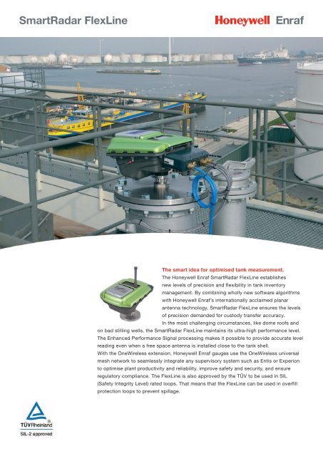
The smart idea for optimised tank measurement.<br />
The Honeywell Enraf <strong>SmartRadar</strong> <strong>FlexLine</strong> establishes<br />
new levels of precision and flexibility in tank inventory<br />
management. By combining wholly new software algorithms<br />
with Honeywell Enraf’s internationally acclaimed planar<br />
antenna technology, <strong>SmartRadar</strong> <strong>FlexLine</strong> ensures the levels<br />
of precision demanded for custody transfer accuracy.<br />
In the most challenging circumstances, like dome roofs and<br />
on bad stilling wells, the <strong>SmartRadar</strong> <strong>FlexLine</strong> maintains its ultra-high performance level.<br />
The Enhanced Performance Signal processing makes it possible to provide accurate level<br />
reading even when a free space antenna is installed close to the tank shell.<br />
With the OneWireless extension, Honeywell Enraf gauges use the OneWireless universal<br />
mesh network to seamlessly integrate any supervisory system such as Entis or Experion<br />
to optimise plant productivity and reliability, improve safety and security, and ensure<br />
regulatory compliance. The <strong>FlexLine</strong> is also approved by the TÜV to be used in SIL<br />
(Safety Integrity Level) rated loops. That means that the <strong>FlexLine</strong> can be used in overfill<br />
protection loops to prevent spillage.
Technical specifications<br />
Measuring specifications<br />
Measuring range<br />
: up to 75 m (246 ft)<br />
Instrument accuracy : Xtreme Precision <strong>SmartRadar</strong> ± 0.4 mm (0.016”) *<br />
Measuring resolution<br />
Principles<br />
Measuring principle<br />
Signal processing<br />
Operating frequency<br />
Mechanical<br />
Dimensions<br />
Weight<br />
Cable entries<br />
: High Precision <strong>SmartRadar</strong> ± 1 mm (0.04”) *<br />
: Advanced Precision <strong>SmartRadar</strong> ± 3 mm (0.12”) *<br />
: 0.1 mm (0.001 ft)<br />
: FMCW / Synthesized Pulse Reflectometer<br />
: Enhanced Performance Signal processing (EPS)<br />
: X band (9.538 GHz to 10.561 GHz) R&TTE, FCC compliant<br />
: See drawing opposite<br />
: 10 kg excluding antenna and separator<br />
: 3/4” NPT or M20<br />
Environmental<br />
Ambient temperature : -40 °C to +65 °C (-40 °F to +149 °F)<br />
Storage temperature : -50 °C to +75 °C (-58 °F to +167 °F)<br />
Protection class : IP66 / IP67 according to EN 60529 (NEMA 4X)<br />
Safety<br />
: Explosion proof<br />
- ATEX II 1/2 G Ex d IIB T6 or Ex d [ia] IIB T6 or<br />
Ex de IIB T6 or Ex de [ia] IIB T6<br />
- IEC Ex Zone 0/1 Ex d IIB T6 or Ex d [ia] IIB T6 or<br />
Ex de IIB T6 or Ex de [ia] IIB T6<br />
- Class I, Division 1, Groups C and D, acc. to ANSI / NFPA 70 (FM, CSA)<br />
Materials<br />
Instrument unit housing : Aluminum alloy according to EN1706<br />
Instrument unit finish : Hard anodising according to MIL A8625-E Type III<br />
O- rings : NBR 70<br />
Electrical<br />
Power supply<br />
Power rating<br />
: autoselect 65 Vac to 240 Vac (+10 % to -15 %) 50 / 60 Hz<br />
autoselect 24 Vdc to 65 Vdc (+10 % to -15 %)<br />
: Typical 15 W max. 23 W with options<br />
Safety & approvals<br />
ATEX, CE, IECEx, OIML, CB Scheme, FM, CSA, FCC, API, NMi, TÜV certified Overfill Protection,<br />
DIBT Overfill Protection<br />
Wireless communication<br />
Wireless Communication<br />
DSSS RF Transmitter Power<br />
Signal Range Nominal<br />
: 2,400 to 2,483.5 MHz (2.4 GHz) Industrial, Scientific and Medical (ISM) band<br />
Modulation: DSSS – Discrete Sequential Spread Spectrum per<br />
FCC 15.247 / IEEE802.15.4-2006<br />
: NA Selection – 125 mW (20.9 dBm) maximum transmit power not including<br />
antenna per FCC/IC, or 400 mW (26.0 dBm) maximum EIRP including antenna<br />
for USA and Canadian locations<br />
EU Selection – 10 mW (10.0 dBm) maximum EIRP including antenna per<br />
RTTE/ETSI for EU locations<br />
: Per FCC/IC 2800 m (9000 feet)<br />
Per RTTE/ETSI 600 m (1970 feet)<br />
between Field Transmitter and Infrastructure Unit (Multinode) or Gateway Unit when<br />
using 8 dBi Integral antenna with a clear line of sight<br />
Options<br />
5 module slots available, for all type of interface solutions see next page<br />
Note:<br />
*) Under reference conditions
Options<br />
Temperature and Water Level Measurement (FII-VT)<br />
The heterogeneous thermal expansion and subsequent stratified temperature build-up in tanks<br />
of 5000 barrels and larger require an averaging of the vertical temperature to calculate the<br />
liquid’s volume at reference conditions (15ºC, 1 bar). As the vertical temperature gradient in<br />
tanks is rarely linear (differences of 5ºC are considered common) the accuracy of the average<br />
temperature definition depends on the number of spot elements. Higher tanks as a result require<br />
more spot elements, not only to better define the total volume but also to more adequately<br />
compensate for tank storage side effects, such as tank shell temperature expansion and liquid<br />
in the vapor phase, as these become more evident in large storage tanks.<br />
Honeywell Enraf offers a complete portfolio of Automatic Tank Thermometers (ATT) that provides<br />
an accurate average product temperature measurement and, as an option, vapor temperature measurement and/or a<br />
temperature profile. The Versatile In-tank Temperature Observer (VITO) portfolio consists of two types, comprising<br />
16 or 9 elements, with or without water-bottom measurement. The 16 elements version is used for W&M approved average<br />
temperature measurement; the 9 elements version can be used in less demanding applications. Both product lines are fully<br />
compliant with industrial standards such as ISO and API.<br />
The FII-VT option provides averaged and/or individual temperature and water-bottom readings for inventory management<br />
purposes. The intrinsically safe module provides immediate, fast and complex calculations and uses HART communication.<br />
Benefits<br />
• VITO exceeds Weight & Measures requirements and therefore guarantees cost efficiency<br />
• Lower installed costs because of integrated water bottom measurement<br />
• Integrated tank shell temperature, vapor phase temperature and profiling<br />
Technical Specifications<br />
Max. instruments per line : 1<br />
Communications<br />
: Proprietary HART (Ex-i)<br />
Cable characteristics : 2 wire shielded 0.5 mm2<br />
Max. cable length<br />
: Compliant to HART specifications<br />
Spot Temperature Interface RTD (FII-RTD)<br />
New to the <strong>SmartRadar</strong> <strong>FlexLine</strong> offering is the RTD temperature sensor support.<br />
As all available options, this is an integrated solution where the sensors can be connected directly<br />
without interface equipment. The RTD offering is the most accurate temperature measurement<br />
available this option is fully W&M approved and conforms to the applicable API standards. The high<br />
diagnostic coverage allows automatic compensation in case one of the temperature sensors fails.<br />
The RTD interface in the <strong>FlexLine</strong> is compatible with all temperature sensors available on the market<br />
today. Up to 6 elements can be connected. Migration from existing level measurements to the<br />
<strong>FlexLine</strong> is easy, straightforward and cost effective.<br />
Benefits<br />
• Lower installed cost: does not require additional interfacing equipment<br />
• Integrated diagnostics allow automatic compensation if one spot fails<br />
• Compatible with all temperature sensors available<br />
Technical Specifications<br />
Cable characteristics<br />
Max. cable length<br />
: Shielded Rmax = 100 Ω / line<br />
: 150 meter
Wireless Connectivity (HCI-1WL)<br />
The Honeywell Enraf <strong>FlexLine</strong> establishes new levels of precision and flexibility in tank<br />
inventory management. By combining wholly new software algorithms with Honeywell Enraf’s<br />
internationally acclaimed planar antenna technology, <strong>FlexLine</strong> ensures the levels of precision<br />
demanded for custody transfer accuracy. In the most challenging circumstances, like dome<br />
roofs and on bad stilling wells, the <strong>SmartRadar</strong> <strong>FlexLine</strong> maintains its ultra-high performance<br />
level. The Enhanced Performance Signal processing makes it possible to provide accurate<br />
level reading even when a free space antenna is installed close to the tank shell. With the<br />
OneWireless extension, Honeywell Enraf gauges use the OneWireless universal mesh network,<br />
to seamlessly integrate with any supervisory system such as Entis or Experion. OneWireless<br />
helps optimize plant productivity and reliability, improve safety and security, and ensure regulatory compliance. The <strong>FlexLine</strong><br />
integrated with the OneWireless is simple to manage and efficient to operate.<br />
Benefits<br />
• Slash installation cost by 50% or more through wireless connectivity<br />
• Improve measurement accuracy by inexpensively migrating to high-precision radar measurements<br />
• Reduce operational costs by integrating wired and wireless devices in the same tank management software<br />
Technical Specification<br />
Frequency Band<br />
Connectivity<br />
Publication data<br />
Publish Cycle Time<br />
Protocol Tunnels<br />
: 2,400 to 2,483.5 MHz (2.4 GHz) Industrial, Scientific and Medical (ISM) band,<br />
DSSS Modulation – per FCC 15.247 / IEEE 802.15.4–2006<br />
: Level and temperature data block.<br />
: Configurable as 1, 5, 10 or 30 seconds<br />
: GPU and FlexConn protocol<br />
Transmitter power<br />
NA<br />
: 100 mW (20 dBm) maximum transmit power not including antenna per FCC/IC,<br />
or 36.0 dBm maximum EIRP including antenna for USA and Canada<br />
EU<br />
: 10 mW (10.0 dBm) maximum EIRP including antenna per RTTE/ETSI<br />
Antennas<br />
Integral<br />
: 4 dBi omnidirectional monopole with lightning surge arrestor – 8 dBi omni-directional<br />
monopole with lightning surge arrestor<br />
Remote<br />
: – 8 dBi omnidirectional monopole with cable and lightning surge arrester<br />
Surge Arrestor : Gas tube element breakdown voltage: 90V +/- 20%,<br />
Impulse breakdown voltage : 1000V +/- 20%. Maximum withstand current 5 KA
HART and Analog Input Connectivity (FCI-HT)<br />
Master<br />
HART is widely recognized as the industry standard for digitally enhanced 4-20mA instrument<br />
communication. It enables digital communication while maintaining the integrity of the 4 to 20 mA<br />
signal and results in the availability of information beyond the normal variable (PV) communicated.<br />
Hydrostatic Tank Gauging and Hybrid Inventory Measuring Systems, based on density in<br />
combination with level measurement for accurate inventory determination, comprise HART capable<br />
(spot) temperature and pressure transmitters. Water bottom detection is one of the other alternative<br />
examples of HART communication.<br />
The FCI-HT module is a HART master module that can be installed inside the <strong>FlexLine</strong> and supports<br />
all HART capable device.<br />
Benefits<br />
• Allows further inventory optimization by integration of temperature and pressure measurements<br />
• Multiple HART devices and modules can be installed into one <strong>FlexLine</strong> gauge<br />
• Can be used as data-concentrator for other measurements such as roof tilt indication, (rim) fire detection, ambient<br />
temperature measurement, floating roof compensation, etc.<br />
Technical Specification<br />
Max. instruments per line<br />
Communications<br />
Cable characteristics<br />
Cable length<br />
: 5 (digital), 1 (analog)<br />
: HART (Ex-i)<br />
: Shielded, twisted pair<br />
: Compliant to HART specifications<br />
HART and Analog Output Connectivity (HCI-HAO)<br />
Slave<br />
The <strong>FlexLine</strong> series is now available as a HART compatible device. This allows the <strong>FlexLine</strong> to be<br />
connected to any operational interface or other device that supports HART. All level information,<br />
parameters and diagnostics can be transferred to the operator HMI via this interface stack.<br />
The HART information can also be routed via the OneWireless infrastructure. Due to the modular<br />
architecture of the <strong>FlexLine</strong>, multiple HART interfaces can be integrated into one gauge.<br />
Benefits<br />
• Lower installed cost<br />
- Multiple supervisory systems can connect up to one <strong>FlexLine</strong><br />
- Connection to any HART capable HMI<br />
- Installed next to regular BPM communication<br />
Technical Specification<br />
Communications<br />
Cable characteristics<br />
Cable length<br />
: HART<br />
: Shielded, twisted pair<br />
: Compliant to HART specifications
Alarm and Overfill Digital Outputs (FII-DO)<br />
Digital outputs are typically used to provide on/off control for valves, dampers, motors, pumps and<br />
external signaling devices, such as alarm bells and indicator lights. The most common devices<br />
associated with digital outputs are relays, contactors, starters and two-position actuators.<br />
The FII-DO module provides multiple relay contacts that can be controlled remotely or switched<br />
automatically and linked to any software property available setting in the <strong>FlexLine</strong>.<br />
When any of the primary values (level) or secondary values (product level, water level, product<br />
temperature, density, vapor pressure etc.) reaches a certain configured value, the digital outputs can<br />
be activated or deactivated. All contact outputs thereby provide automatic read-back functionality<br />
for higher safety and increased diagnostics. The FII-DO provides 4 Single Pole Single Throw (SPST)<br />
relays that can be manually set to normally open or normally closed. All 4 relays have been certified by the TUV.<br />
Due to the modular architecture of the <strong>FlexLine</strong>, multiple digital output modules can be integrated into one gauge.<br />
SIL-2<br />
<strong>FlexLine</strong> is approved by the TÜV to be used in SIL (Safety Integrity Level) rated loops. That means that the <strong>FlexLine</strong> can be used<br />
in overfill protection loops to prevent spillage. <strong>FlexLine</strong> gauge has a SFF (Safe Failure Fraction) > 90% which allows it to be used<br />
in SIL-2 safety loops. Diagnostics within the gauge have improved such that the safety proof-test interval can be extended to 5<br />
years. This will bring down the operational cost. On top of that, the safety function in the gauge makes use of dual redundancy<br />
which will automatically detect failures in the safety circuitry, report those failures, but still allows the gauge to continue to function<br />
as a safety device without interrupting the process. This allows for a higher availability compared with competitive offerings.<br />
The SIL-2 option is only available when the FII-DO is used in redundant module configuration.<br />
Benefits<br />
• Approved by TÜV to be used in SIL-2 rated loops; SIL-3 if used in redundant Radar configuration<br />
• Proof test interval of 5 years to reduce operational cost<br />
• Dual redundant module configuration increases safety as well as availability<br />
• Ultimate the flexibility: any radar measurement can be used to trigger external devices<br />
Technical Specification<br />
Relays<br />
Relay 1&2<br />
Relay 3&4<br />
Time delay<br />
: 4 SPST contacts, NC or NO function selectable (default NO)<br />
: Rated 0.5 A at 125 Vac or 0.3 A at 110 Vdc Pmax = 30 W<br />
: Rated 3 A at 250 Vac or 3 A at 40 Vdc Pmax = 750 W<br />
: 5 to 10 ms duration<br />
Remote and Integrated Display Connection to SmartView (FII-SMV)<br />
Honeywell Enraf offers the SmartView LCD display interface as a standalone and integrated solution<br />
to its field instrumentation portfolio. The SmartView can be used to configure, monitor and troubleshoot<br />
the <strong>FlexLine</strong> radar family.<br />
<strong>FlexLine</strong> data as well as inventory related information is available with a maximum distance of 50 m<br />
from the instrument. Irrespective of the position of the interface the SmartView offers consistency,<br />
simplicity and direct access to last measured values, 24 hour trending, device and commissioning<br />
status, etc. The FII-SMV module enables the connection of a local or remote SmartView to any<br />
<strong>FlexLine</strong> in the facility. The special connection enables hot plug in hazardous areas.<br />
Benefits<br />
• Standalone as well as integrated display<br />
• One display can be used for multiple gauges and is hot plugable<br />
• Can be installed up to 250 m from actual instrument<br />
Technical Specification<br />
Max. displays that can be Baudrate : min 19200 bps<br />
connected : 2 Cable characteristics : 4 wire shielded 0.5 mm2<br />
Communications : isolated RS-485 port, Max. cable length : up to 250 m<br />
propriety protocol (Ex-i) Power out display : 9.4 Vdc (Ex-i)
Serial Host Communication Interface (HCI-GPU)<br />
The HCI-GPU can be used in any field device provided with the FlexConn architecture such as the<br />
<strong>FlexLine</strong> and enables communications through the RS-232/485 physical layers. RS-232 is often used<br />
for direct point-to-point connection whereas RS-485 facilitates a multi-point network with up to 32<br />
connected devices on a 2-wire or 4- wire bus. Used communication protocols are Modbus or the<br />
Gauge Processing Unit (GPU) protocol. GPU has become the standard in terminal automation.<br />
Both protocols are used to get data from the field instrumentation to supervisory level. The GPU<br />
protocol is unique because it is W&M approved, has error recovery mechanism and can be used for<br />
long distances. The advantages of using HCI-GPU board are:<br />
• Communication can be redundant for higher integrity and availability<br />
• Can be used dual redundant with other communication protocols such as wireless, BPM or HART<br />
• Short refresh rate (< 1 second) allowing more connected devices<br />
• RS-485 can cover long distances and reduces the cost of infrastructure<br />
• Modbus and GPU are open protocols and widely accepted<br />
• Backwards compatible with Honeywell Enraf equipment<br />
• Further enhances the data concentrator role to pass all tank related measurements to the operational level.<br />
• It supports the automatic proof test which will increase the safety of a tank<br />
• Unique protocol switch that allows 2 different protocols on one physical link<br />
• W&M approved<br />
Technical Specification<br />
Connectivity<br />
Max. instruments per line<br />
Baudrate<br />
Cable Characteristics<br />
Max. cable length<br />
Protocol<br />
: RS-232 (isolated & non isolated)<br />
: 1, point to point<br />
: 1200, 2400, 4800, 9600, 19200, 38400bps, 56 Kbps, 115 Kbps, configurable by software<br />
: Shielded / twisted pair<br />
: 15 m<br />
: GPU and Modbus<br />
Connectivity<br />
Max. instruments per line<br />
Baudrate<br />
Cable Characteristics<br />
Max. cable length<br />
Protocol<br />
: RS-485 (isolated)<br />
: 32, multi point<br />
: 1200, 2400, 4800, 9600, 19200, 38400bps, 56 Kbps, 115 Kbps, configurable by software<br />
: Shielded + twisted pair + signal ground, R 0.12 Ω / line, C 119 pF/m, L 1.45 mH<br />
: 1200 m<br />
: GPU and Modbus<br />
Bi-Phase Mark Host Communication Interface (HCI-BPM)<br />
Bi-Phase Mark (BPM) is the current industry standard in terminal automation systems.<br />
It allows for cable lengths up to 10 kilometer (6 miles), can run over existing infrastructure,<br />
and only needs 2-wires and can connect up 15 devices per fieldbus. Bi-Phase Mark (BPM)<br />
has been applied in many installations world wide for data transmission between various<br />
instruments and Communication Interface Units (CIU). Honeywell Enraf offers BPM through a<br />
specially developed isolation transformer that is employed on both ends of the communication<br />
line, therefore no additional lightning protection is needed as this has been embedded in<br />
the design. The Honeywell Enraf HCI-BPM can be installed in any field device that uses the<br />
FlexConn architecture such as the <strong>FlexLine</strong>.<br />
Benefits<br />
• Can use existing infra structure<br />
• Robust<br />
• Defacto standard in terminal automation<br />
Technical Specification<br />
Max. instruments per BPM line : 10 - 15<br />
Baudrate<br />
: 1200, 2400 bps<br />
Cable characteristics : twisted, Rmax 200 Ω / line, Cmax 1 μF<br />
Max. cable length<br />
: 10 km<br />
Protocol<br />
: proprietary GPU
Identification code<br />
Pos 1 Device selection No. of terminals No. of Slots<br />
i.s. non i.s.<br />
R <strong>SmartRadar</strong> <strong>FlexLine</strong> 1<br />
Pos 2 Type of gauge<br />
X Xtreme Performance, W&M type approved with factory calibration report and sealing facilities 4 )<br />
Y Xtreme Performance, W&M type approved<br />
H High Performance, for custody transfer acc. to OIML R85, API 3.1B and ISO 4266<br />
I High Performance, for custody transfer acc. to OIML R85, API 3.1B and ISO 4266 with factory calibration report<br />
A Advanced Performance, for inventory control acc. to API 3.1B and ISO 4266<br />
U Advanced Performance, for inventory control acc. to API 3.1B and ISO 4266 with factory calibration report<br />
Pos 3 Display<br />
I Including integrated SmartView display 1<br />
V With IS terminal for connecting stand alone SmartView 4 1<br />
B With integrated SmartView display and IS terminal for connecting stand alone SmartView 4 1<br />
Z No display 1<br />
Pos 4 Data transmission<br />
B Enraf Fieldbus Bi-Phase Mark (BPM), GPU protocol 2 1<br />
G RS-232, GPU / Modbus protocol 3 1<br />
H Combined HART and 4-20 mA output 2 1<br />
1 One Wireless (this option board uses two slots on the CAN bus) 5 ) 0 2<br />
W RS-485, GPU / Modbus protocol 3 1<br />
Pos 5 I/O Options<br />
- None 0<br />
V VITO temp. and/or water sensor interface 2 1<br />
Q HART input for HART communications 2 1<br />
R HART input for HART communications + HTMS (HIMS) density calculations 2 1<br />
C Hardware alarms (SPDT NO/NC) contact outputs (2x) 125 Vac, 0.5 A (110 Vdc, 0.3A) 4 1<br />
N Hardware alarms (SPDT NO/NC) contact outputs (2x) 250 Vac, 3 A (40 Vdc, 3A) 4 1<br />
O Hardware alarms (SPDT NO/NC) contact outputs (4x) combination of options C and N 8 1<br />
S RTD one spot element 3-wire 3 1<br />
T RTD one spot element 4-wire 4 1<br />
U RTD two spot elements 3-wire 6 1<br />
X RTD two spot elements 4-wire 8 1<br />
2 RTD 2 elements MRT / MPT 4 1<br />
3 RTD 3 elements MRT / MPT 5 1<br />
4 RTD 4 elements MRT / MPT 6 1<br />
5 RTD 5 elements MRT / MPT 7 1<br />
6 RTD 6 elements MRT / MPT 8 1<br />
Z SIL compliance (this option board uses two slots on the CAN bus) 2 2<br />
Pos 6, 7, 8 Additional Data transmission and/or I/O Options<br />
Select code from Pos. 4 and 5 Total: *) **) ***)<br />
Select code from Pos. 5 1 ) 2 ) 6 )<br />
Select code from Pos. 5 1 ) 3 ) 6 )<br />
Pos 9 Safety approvals<br />
A ATEX / IEC Ex Europe<br />
F FM (only if pos. 10=C or M) USA<br />
C CSA Canada<br />
I INMETRO Brazil<br />
Pos 10 Cable entries<br />
S Ex e terminal compartment with 4 cable entries (4xM20) (only if Pos 9 = A, C or I)<br />
E Ex e terminal compartment extended to 6 cable entries (6xM20) (only if Pos 9 = A, C or I)<br />
C 3x 3/4” NPT (Compound cable glands required)<br />
M 2x M20<br />
Pos 11, 12, 13 Radar Process Antenna version<br />
F 0 8 8” PAT, Free space<br />
W 0 6 6” x 12” WALP, Free space (only if Pos 2 = A or U)<br />
T 0 6 6” x 12” Hinged WALP, Free space (only if Pos 2 = A or U)<br />
D 0 4 RoD, Free space (only if Pos 2 = A or U)<br />
S 0 6 6” PAT, Stilling well<br />
S 0 8 8” PAT, Stilling well<br />
S 1 0 10” PAT, Stilling well<br />
S 1 2 12” PAT, Stilling well<br />
H 0 4 4” Horn, High pressure<br />
Pos 14, 15 Stem length / Application type<br />
x x 0 mm (only if Pos 11 = D)<br />
0 5 50 mm (Not if Pos 11 = D, H, W or T)<br />
3 0 300 mm (Not if Pos 11 = D or H)<br />
5 0 500 mm (Not if Pos 11 = D or H)<br />
8 0 800 mm (Not if Pos 11 = D or H)<br />
B 1<br />
Installation on 6” 300 lbs nozzle with 4” Schedule 10 stilling well<br />
(only if Pos 11 = H)<br />
B 4 Installation on 4” 300 lbs full bore ball valve (only if Pos 11 = H)<br />
N 1<br />
Installation on 6” 300 lbs nozzle with 4” Schedule 10 stilling well<br />
including 1” full bore ball valve (only if Pos 11 = H)<br />
N 4 Installation on 4” 300 lbs Schedule 40 nozzle including 1” full bore ball valve (only if Pos 11 = H)<br />
Pos 16 OneWireless Communication Antenna<br />
- None (not if Pos 4, 6 =1)<br />
A 4 dBi antenna (only if Pos 4, 6 = 1)<br />
B 8 dBi antenna (only if Pos 4, 6 = 1)<br />
Pos 17 Tag plate<br />
Z No tag plate<br />
T Tag plate (Material: CuNi alloy)<br />
R X I B V - - - A S F 0 8 3 0 A Z Typical identification code<br />
R Your identification code<br />
Notes:<br />
Green marked positions : express delivery<br />
Blue marked positions : normal delivery<br />
For delivery times please contact your local sales office<br />
*) Maximum sum of i.s. terminals is 10<br />
**) Maximum sum of non-i.s. terminals is 15<br />
***) Maximum number of slots = 7<br />
1<br />
) Max. 2 identical I/O options<br />
2<br />
) Not available if SIL compliance and One Wireless is selected<br />
3<br />
) Not available if SIL compliance or One Wireless is selected<br />
4<br />
) For witnessed verification specify authority; for more information<br />
please contact factory<br />
5<br />
) Please make sure the wireless <strong>FlexLine</strong> complies to local radio regulations<br />
6<br />
) If additional data transmission options are needed please consult factory
Installation drawings<br />
High pressure cone type H04<br />
Tank seperator<br />
option:<br />
Flange adapter 4", 300 lbs<br />
Spool piece 4", 300 lbs<br />
Full bore ball valve 4", 300 lbs<br />
option:<br />
Flange adapter<br />
4", 300 lbs<br />
option:<br />
Flange adapter<br />
6", 300 lbs<br />
option:<br />
Flange adapter<br />
6", 300 lbs<br />
ø101 mm (4")<br />
ø107 mm (4 3/16" )<br />
Installation on<br />
4" ball valve<br />
(type H04B4)<br />
Horn: length 360 mm (1' 2 3/16" )<br />
Installation in<br />
4" SCH10s insert pipe<br />
(type H04B1)<br />
Horn: length 410 mm (1' 41/8"<br />
)<br />
Full bore<br />
ball valve<br />
1", 300 lbs<br />
Full bore<br />
ball valve<br />
1", 300 lbs<br />
ø101 mm (4")<br />
ø107 mm (4 3/16" )<br />
Installation in<br />
4" SCH40 still pipe<br />
(type H04N4)<br />
Horn: length 360 mm (1’ 2 )<br />
Installation in<br />
4" SCH10s insert pipe<br />
(type H04N1)<br />
Horn: length 410 mm (1' 4 )<br />
3/16" 1/8"<br />
High pressure cone type H04<br />
Measuring range : Up to 75 m (246 ft)<br />
Temperature range : -200 °C to +250 °C (-330 °F to +482 °F)<br />
Operating pressure : Up to 40 bar / 4 MPa (580 psi)<br />
Wetted parts<br />
: AISI 316, PTFE and CF8M for optional ball valve
Free space type F06 and F08<br />
Tank separator<br />
Optional:<br />
flange or adapter plate<br />
Circlip<br />
Antenna stem nut<br />
Circlip<br />
Antenna stem nut<br />
Ø139 mm (51/2”)<br />
45 mm<br />
(1 3/4" )<br />
Ø189.5 mm (71/2”<br />
)<br />
Free space types F06, F08 & Still pipe types S06, S08, S10 and S12<br />
Measuring range : Up to 75 m (246 ft)<br />
Temperature range : -40 °C to +100 °C (-40 °F to +212 °F)<br />
Operating pressure : Up to 6 bar / 0.6 MPa (87 psi)<br />
Wetted parts<br />
: AISI 316 and FEP<br />
Still pipe types S06, S08, S10 and S12<br />
Tank separator<br />
optional:<br />
flange or adapter plate<br />
Circlip<br />
Antenna stem nut<br />
”A”<br />
for S06 = ø139 mm (5 )<br />
for S08 = ø189.5 mm (7 7/16" )<br />
for S10 = ø239 mm (9 7/16" )<br />
for S12 = ø289 mm (11 3/8" )<br />
”A”<br />
1/2"
Dimensional drawing<br />
SmartConn Ex-e<br />
Junction box<br />
Cable Entries<br />
M20 (2x) or<br />
3 4 '' NPT (3x)<br />
Cable Entries via<br />
SmartConn Ex-e<br />
Junction box<br />
M20 (4x optional 6x)<br />
Rear View without SmartConn<br />
Rear View with SmartConn<br />
Dimensions in mm / inches
For More Information<br />
To learn more about Honeywell Enraf’s<br />
solutions, contact your Honeywell Enraf<br />
account manager or visit<br />
www.honeywellenraf.com.<br />
Americas<br />
Honeywell Enraf Americas, Inc.<br />
2000 Northfield Ct.<br />
Roswell, GA 30076<br />
USA<br />
Phone: +1 770 475 1900<br />
Email: enraf-us@honeywell.com<br />
Asia Pacific<br />
Honeywell Pte Ltd.<br />
17 Changi Business Park Central 1<br />
Singapore 486073<br />
Phone: +65 6355 2828<br />
Email: enraf-sg@honeywell.com<br />
Europe, Middle East and Africa<br />
Honeywell Enraf<br />
Delftechpark 39<br />
2628 XJ Delft<br />
The Netherlands<br />
Phone: +31 (0)15 2701 100<br />
Email: enraf-nl@honeywell.com<br />
EN-09-21-ENG_Rev.6<br />
August 2012<br />
© 2012 Honeywell International Inc.


