Digital Competitive Precision Projectile Table Support Structure
Digital Competitive Precision Projectile Table Support Structure
Digital Competitive Precision Projectile Table Support Structure

Create successful ePaper yourself
Turn your PDF publications into a flip-book with our unique Google optimized e-Paper software.
<strong>Digital</strong> <strong>Competitive</strong> <strong>Precision</strong><br />
<strong>Projectile</strong> <strong>Table</strong> <strong>Support</strong><br />
<strong>Structure</strong><br />
Christian Braun, Rashon Hogan, Jelani Jackson,<br />
Donald Thomson<br />
University of Central Florida, College of<br />
Engineering and Computer Science, Orlando,<br />
Florida, 32816, U.S.A.<br />
Abstract — The mixture of a college student’s past time<br />
and technology brings the <strong>Digital</strong> <strong>Competitive</strong> <strong>Precision</strong><br />
<strong>Projectile</strong> <strong>Table</strong> <strong>Support</strong> <strong>Structure</strong> (DCPPTSS). Beer pong<br />
has been seen popping up around college campuses in the<br />
United States sometime around the 1950s and 1960s. The<br />
game of beer pong has received a technological upgrade<br />
which allows for players to continue enjoying the game while<br />
possibly being slightly inebriated. These upgrades range from<br />
ball detection, current player indicator, score keeping, game<br />
correction in case foul play is involved, and a ball washer to<br />
handle possible bacteria.<br />
Index Terms — Beer pong, capacitive touch, digital<br />
integrated circuit, diode lasers, inter-integrated circuit,<br />
microcontroller.<br />
I. INTRODUCTION<br />
From the time of its inception, beer pong has become<br />
the college student’s game of choice. A break from the<br />
rigors of studying, term papers, and exams, beer pong has<br />
become a way where people get together in a social<br />
environment have fun playing a game. It is a little more<br />
active than playing a game of cards, but much skill is not<br />
required. The only skill one needs to play beer pong is the<br />
skill of precision. Beer pong is usually played with two<br />
teams with two players per team. Each team begins the<br />
game by standing at the ends of the table behind their cup<br />
setup called a rack. A rack is the number of cups, which in<br />
the beginning ranges from 6 to 12 cups, in a geometric<br />
shape, and each team throws ping pong balls into the<br />
opponent’s cups until none are remaining. The initial<br />
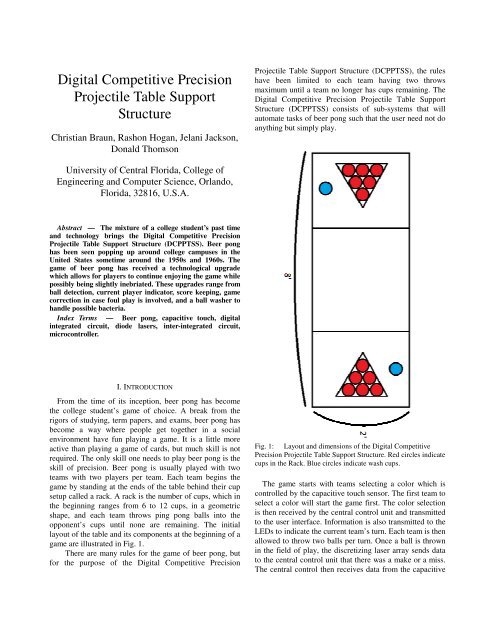
layout of the table and its components at the beginning of a<br />
game are illustrated in Fig. 1.<br />
There are many rules for the game of beer pong, but<br />
for the purpose of the <strong>Digital</strong> <strong>Competitive</strong> <strong>Precision</strong><br />
<strong>Projectile</strong> <strong>Table</strong> <strong>Support</strong> <strong>Structure</strong> (DCPPTSS), the rules<br />
have been limited to each team having two throws<br />
maximum until a team no longer has cups remaining. The<br />
<strong>Digital</strong> <strong>Competitive</strong> <strong>Precision</strong> <strong>Projectile</strong> <strong>Table</strong> <strong>Support</strong><br />
<strong>Structure</strong> (DCPPTSS) consists of sub-systems that will<br />
automate tasks of beer pong such that the user need not do<br />
anything but simply play.<br />
Fig. 1: Layout and dimensions of the <strong>Digital</strong> <strong>Competitive</strong><br />
<strong>Precision</strong> <strong>Projectile</strong> <strong>Table</strong> <strong>Support</strong> <strong>Structure</strong>. Red circles indicate<br />
cups in the Rack. Blue circles indicate wash cups.<br />
The game starts with teams selecting a color which is<br />
controlled by the capacitive touch sensor. The first team to<br />
select a color will start the game first. The color selection<br />
is then received by the central control unit and transmitted<br />
to the user interface. Information is also transmitted to the<br />
LEDs to indicate the current team’s turn. Each team is then<br />
allowed to throw two balls per turn. Once a ball is thrown<br />
in the field of play, the discretizing laser array sends data<br />
to the central control unit that there was a make or a miss.<br />
The central control then receives data from the capacitive
touch sensor that confirms or denies the reading from the<br />
discretizing laser array, based on whether or not a cup is<br />
removed from the table. If a ball is thrown, and misses the<br />
table, the user inputs a miss via the user interface. Once all<br />
the cups on one side of the table have been removed from<br />
play, the opposing team is determined to be the winner of<br />
the game.<br />
II. SYSTEM COMPONENTS<br />
The <strong>Digital</strong> <strong>Competitive</strong> <strong>Precision</strong> <strong>Projectile</strong> <strong>Table</strong><br />
<strong>Support</strong> <strong>Structure</strong> (DCPPTSS) is comprised of various<br />
components which allow the user to focus less on<br />
remembering the specifics of the game and more on<br />
playing the game itself.<br />
A. Central Control<br />
The system that will control majority of the systems<br />
used in the <strong>Digital</strong> <strong>Competitive</strong> <strong>Precision</strong> <strong>Projectile</strong> <strong>Table</strong><br />
<strong>Support</strong> <strong>Structure</strong> is a MSP430G2553 microcontroller. As<br />
the central control unit, the MSP430G2553<br />
microcontroller is responsible handling data that is sent to<br />
and received by the surrounding sub-systems. The subsystems<br />
the MSP430G2553 microcontroller communicates<br />
with that have a direct connection to the functions of the<br />
gameplay are the discretizing laser array, user interface<br />
and the capacitive touch sub-systems. The MSP430G2553<br />
microcontroller is also be responsible for the reduction in<br />
power consumption, keeping score of the game, keeping<br />
track of the number of throws remaining per turn,<br />
changing LED location once player turn is over, as well as<br />
the number of cups remaining on the table for each player.<br />
MSP430G2553 microcontroller needs a way to<br />
communicate that data, both input and output. When<br />
communicating that data between a sub-system such as the<br />
discretizing laser array and the capacitive touch subsystems<br />
it is best to have a communication method where<br />
there is an order in terms of priority. The priority being the<br />
MSP430G2553 microcontroller has the highest priority<br />
while the sub-systems follow. This method of<br />
communication is necessary due to the fact that the<br />
MSP430G2553 microcontroller is the central control unit.<br />
If a sub-system were to have higher priority over the<br />
MSP430G2553 microcontroller then the MSP430G2553<br />
would in fact not be the center of control. The<br />
MSP430G2553 microcontroller will need full control over<br />
the sub-systems. The central control will implement a<br />
master-slave communication system in which Inter-<br />
Integrated Circuit (I 2 C) provides. Another part of the<br />
<strong>Digital</strong> <strong>Competitive</strong> <strong>Precision</strong> <strong>Projectile</strong> <strong>Table</strong> <strong>Support</strong><br />
<strong>Structure</strong> is the communication between the<br />
MSP430G2553 microcontroller and the discretizing laser<br />
array sub-system. The discretizing laser array system,<br />
when not in sleep mode, will buffer to wait for a projectile,<br />
the ball, to enter its laser field. Once the projectile enters<br />
the field the MSP430G2553 microcontroller will be<br />
interrupted by the discretizing laser array sub-system. If a<br />
projectile enters the discretizing laser array field and it is<br />
not over one of the cups, a miss is generated. This<br />
generated miss will be sent to the MSP430G2553<br />
microcontroller which will in turn be sent to the user<br />
interface module for display on the LCD. If a projectile<br />
enters the discretizing laser array field over the opening of<br />
one of the cups, a hit will be generated. This generated hit<br />
will be sent to the MSP430G2553 microcontroller which<br />
in turn will be sent to the user interface module for display<br />
on the LCD.<br />
Communication between the MSP430G2553<br />
microcontroller and the capacitive touch sub-system are<br />
another part of the <strong>Digital</strong> <strong>Competitive</strong> <strong>Precision</strong><br />
<strong>Projectile</strong> <strong>Table</strong> <strong>Support</strong> <strong>Structure</strong>. The capacitive touch<br />
sub-system, when not in sleep mode, will buffer to wait for<br />
a change in capacitance. This change in capacitance will<br />
not occur from a projectile entering a cup, but from the<br />
removal of a cup from the DCPPTSS surface. The<br />
MSP430G2553 microcontroller will then receive an<br />
interrupt from the capacitive touch sensor when there has<br />
been a change in capacitance from the reference which is<br />
taken at the beginning of the game. Once the<br />
MSP430G2553 microcontroller receives the information<br />
from the capacitive touch system, the MSP430G2553<br />
microcontroller will send a request to the corresponding<br />
capacitive touch sensor to turn off the LEDs for the<br />
duration of the game. The results of the remaining<br />
capacitive touch sensors will then be sent to the user<br />
interface as the cups remaining.<br />
When it comes to keeping score of the game the<br />
MSP430G2553 microcontroller will not use an external<br />
system for this task, however, another system will display<br />
all the information. The MSP430G2553 microcontroller<br />
itself will keep track of the score. The functions of the<br />
table will be programmed onto the MSP430G2553<br />
microcontroller in the C programming language. The score<br />
for each player will be stored in the variables ScoreA and<br />
ScoreB for the player(s) of player side A and player side<br />
B, respectively. Both of these variables will be initialized<br />
to zero at the beginning of each game. A player’s score<br />
increases by one with each ball that is made. This<br />
increment in score occurs only when the capacitive touch<br />
system senses a change in capacitance for the<br />
corresponding cup. The score variables will be contained<br />
within a scoring function. The scoring function will be<br />
contained within an if statement and called only if the<br />
discretizing laser array system has detected a ball and the
capacitive touch system has received the reading of the<br />
ball’s location.<br />
Keeping track of the number of throws per turn per<br />
player is also an important aspect of the MSP430G2553<br />
microcontroller. This function also will not use an external<br />
system to handle its processes. The function that keeps<br />
track of the number of throws each player(s) has during<br />
their turn will be programmed onto the MSP430G2553<br />
microcontroller in the C programming language. The<br />
variables num_of_throwsA and num_of_throwsB will be<br />
used to store the number of throws remaining for player<br />
side A and player side B, respectively. Both of these<br />
variables will be placed in the game program that will be<br />
used to run the beer pong functions from the<br />
MSP430G2553 microcontroller. Each variable will be<br />
used within separate for loops. The for loop will initialize<br />
the number of throws to two and will decrement by 1 for<br />
each iteration, throw. As long as the number of throws is<br />
greater than zero, the player(s) will continue to throw a<br />
ball. The for loop will buffer until the discretizing laser<br />
array system gets a reading on a ball that was thrown. In<br />
the event that a player completely misses the infrared<br />
detection area a menu option will be available for a user to<br />
manually decrement the number of throws for a particular<br />
player (the MISS function in the user interface).<br />
An added feature to the <strong>Digital</strong> <strong>Competitive</strong> <strong>Precision</strong><br />
<strong>Projectile</strong> <strong>Table</strong> <strong>Support</strong> <strong>Structure</strong> is LEDs moving in a<br />
snake pattern. The snake motion begins as soon as the<br />
<strong>Digital</strong> <strong>Competitive</strong> <strong>Precision</strong> <strong>Projectile</strong> <strong>Table</strong> <strong>Support</strong><br />
<strong>Structure</strong> is turned on. The initial route of the snake<br />
motion is around the entire table. This snake motion will<br />
continue until a user selects which player will start first.<br />
Once the user selects which player will start first, the snake<br />
motion of the LEDs will then move to the area of that<br />
player and continue to perform the snake motion in that<br />
area during the duration of their turn. When the number of<br />
throws for that particular player reaches zero, the LEDs<br />
will then move to the opposition’s side and perform the<br />
snake motion in that area during the duration of that<br />
player’s turn. The snake motion will continue back and<br />
forth until the number of cups for a given player area has<br />
reached zero. At that time the LEDs will continuously<br />
pulse on the player side of the victor.<br />
The task of keeping track of the cups remaining on the<br />
table for both players will not be handed by a sub-system.<br />
The MSP430G2553 microcontroller will be in charge of<br />
keeping track of the number of cups remaining on the table<br />
for both players. The number of cups remaining for each<br />
player will be stored in the variables cups_remainingA and<br />
cups_remainingB which are used for the player(s) on<br />
player side A and player side B, respectively. These<br />
variables will be initialized to six at the beginning of the<br />
game. The game of beer pong will continue as long as the<br />
cups remaining on both player side A and player side B<br />
are greater than zero. The variables cups_remainingA and<br />
cups_remainingB will be used within the remove cup<br />
function. The remove cup function will be called when the<br />
capacitive touch system senses a change in capacitance<br />
from one of the cups. Once the capacitance has been read<br />
from the corresponding cup the appropriate<br />
cups_remaining variable will be decreased by one.<br />
B. User Interface<br />
The User Interface of the DCPPTSS refers to the digital<br />
components with which the players of a game of Beer<br />
Pong will directly interact. The user interface consists of a<br />
single module containing a standalone MSP430G2553, a<br />
16 line by 2 character LCD display (NHD-0216K3Z-FL-<br />
GBW with built-in PIC16F690 to handle the display of<br />
ASCII characters on the screen)[2], and three lighted<br />
buttons used to navigate the user interface. The<br />
components that make up the user interface are laid out as<br />
shown in Fig. 2, and mounted to a wooden face plate. The<br />
16x2 LCD runs off of a 5v power source, while the<br />
MSP430G2553 runs off a 3.3v power source. The<br />
MSP430G2553 sets the output of the display using the<br />
RS232 protocol. Each time players interact with the table<br />
using the user interface, they will affect the flow of the<br />
game. They do this by using the three given buttons to<br />
navigate a menu shown on the display.<br />
i. Menu<br />
Menus will be displayed on the 16x2 LCD. When the<br />
table is first powered on (or at the beginning of a new<br />
game), players will be able to choose which team goes first<br />
by pushing either the left or the right button. The left<br />
button corresponds to the team on the left side of the table<br />
relative to the position of the user interface module. This is<br />
also referred to as player side A by the central control unit.<br />
Once one team is chosen, the LCD then changes to show<br />
the information for the chosen team. The information<br />
displayed includes the game status (Team Number, Cups<br />
Left, and Reracks Left) for the current team. When the<br />
middle button is pressed, the LCD then changes again to<br />
display the four functions that the table will not be able to<br />
handle automatically (i.e. by the other systems). These<br />
functions include Miss, Skip Turn, Forfeit, and Rerack.<br />
These functions are selected by the left and right buttons,<br />
and selected with the middle button. When selected, the<br />
display asks for confirmation from the players by either<br />
pressing the left (for NO) or right (for YES) button. Once<br />
confirmed, the function activates for the current team of<br />
players. The results of these functions are read by the
central control unit through the I2C bus. The display then<br />
returns to display the game status for the current team.<br />
When the turn changes to the other team (when the<br />
current team is out of Throws), the display will then switch<br />
to display the game status for new current team. When a<br />
game ends, the display will once again ask for the team<br />
which goes first, and the Team Number (of the losing<br />
team) will be increased appropriately to allow the winning<br />
team to continue playing on their side of the table and<br />
keep their specific team number. Also, when the central<br />
control unit sends a full reset signal via the I2C bus, the<br />
user interface will be overridden, resetting the cups left,<br />
reracks left, throws left, and even the team numbers.<br />
Fig. 2: This is the layout of the User Interface module. This<br />
module has three arcade game-style light-up buttons and a backlit<br />
16x2 LCD. It is located in the middle of the table, attached to<br />
the side.<br />
ii. Hardware<br />
The three navigation buttons each have a 3.3v white<br />
LED running at 15mA (using a 220 Ohm resistor),<br />
connected to the same power line as the MSP430G2553<br />
such that the LEDs will designate that the MSP430G2553<br />
has power. The buttons each have a single switch<br />
connected to ground as part of their own RC circuit (with a<br />
time constant of 0.033ms: R=33kOhms, C=1uF) to<br />
provide debouncing for the switches. The output of the RC<br />
switch circuits are attached to the MSP430G2553 at pins<br />
1.3, 1.4, and 1.5, which are all inputs with Schmitt-<br />
Triggering[1] to provide a clean digital signal when the<br />
buttons are depressed. Each time a button is pressed, it<br />
triggers an interrupt on the dedicated MSP430G2553. This<br />
allows the players to press a button at any time, regardless<br />
of what output is being displayed. However, this is limited<br />
to handling only one button press at a given time. Players<br />
that press more than one button near-simultaneously see<br />
behavior based on when the signal is actually interpreted<br />
by the MSP430G2553. The advantage of using interrupt-<br />
based buttons is that the MSP430G2553 can be placed in a<br />
low power state while no buttons are pressed. This will<br />
save power in the long-run versus the MSP430G2553<br />
constantly polling the pins to which the buttons are<br />
attached to detect a change in state.<br />
The LCD display runs on a 5v power source, different<br />
from the MSP430G2553, however, the display is back-lit<br />
to be seen in the dark and will let the players know that the<br />
LCD has power. The LCD display is connected to the<br />
MSP430G2553 at the TXD pin (numbered 1.1). The<br />
MSP430G2553 uses the built-in TimerA module to output<br />
to the LCD via the RS232 standard at 9600 baud.<br />
C. Aesthetic LED Array<br />
The lighting system is designed with the ability to cover:<br />
minimum 4 different animation patterns, exclusive control<br />
of minimum 30 separate lights, and only 2 lines of input<br />
for control. Additionally, the game table is referred to in 3<br />
regions. The areas in which the lasers and capacitive<br />
sensors are located are Regions 1 and 2. The area in<br />
between these two regions will be known as Region 0.<br />
Region 1 and Region 2 will both have LED diodes running<br />
around the perimeter of the regions. Region 0 will consist<br />
of two separate strips of LEDs running the sides of the<br />
Region. The main patterns covered are meant to<br />
distinguish which team is on the offensive, victories, or<br />
pauses in game play. The layout of the Regions is shown<br />
in Fig. 3.<br />
The entire array of LEDs is controlled by a system<br />
containing an MSP430G2553 microcontroller, decoders,<br />
and transistors. The microcontroller takes in a 2 line input<br />
and decides which animation sequence to execute. These<br />
input lines utilize I2C, a common serial communication<br />
interface to allow for virtually unlimited pattern selection.<br />
The outputs of microcontroller will go into a matrix of<br />
decoders built to drive various outputs for the animation.<br />
Although the design lacks the ability to choose to power<br />
more than one light at a time, the microcontroller takes no<br />
extra hardware and wiring to create the effect of multiple<br />
lights on at a time. The flicker fusion threshold is<br />
described as the frequency of at which periodic light<br />
pulses appear to be a complete and continuous light source<br />
to the observer. This phenomenon is caused by the<br />
stimulus effect of the photo lasting longer than the period<br />
of time in between light pulses. Generally humans cannot<br />
detect flicker above about 50Hz. For the light intensity of<br />
LEDs, it is more effective to run in the range of kilohertz.<br />
The chosen MSP430G2553 microprocessor uses 5 of its<br />
digital outputs as control lines for the decoders to decide<br />
which LEDs to turn on. Five CD74HC238 active high 3 to<br />
8 decoders are wired to create a 5 to 32 decoder by using 1
decoder to toggle the enable line of the following 4 (see<br />
Fig. 4).<br />
Fig. 3: This represents the layout of the animation Regions on<br />
the table. The LED patterns are controlled by a single<br />
MSP430G2553 outputting to a series of decoders.<br />
Fig. 4: This shows the setup of the smaller decoders to create<br />
the much larger 5 to 32 decoder. One decoder is used to enable<br />
the other four decoders to allow for a greater number of light<br />
patterns.<br />
The entire Aesthetic LED array system exists on 2<br />
printed circuit boards. One printed circuit board contains<br />
the decoders and the microcontroller and the second<br />
containing the transistors and appropriate resistors.<br />
There is a total of 360 LEDs being driven throughout<br />
the entire system. The LEDs are embedded inside of the<br />
table’s wooden frame and shine though the acrylic top<br />
surface (see Fig. 5). Each transistor is responsible for<br />
driving 12 LEDs. The anodes of the LED (positive leads)<br />
all are connected to provide even power to all LEDs on the<br />
table by a power rail. The cathodes of the LEDs are<br />
connected in groups of 12. Each of these groups are wired<br />
in series to their respective collector nodes of the 2N4401<br />
NPN switching transistors. The output of the active high<br />
decoders is connected to the base node, essentially a<br />
switch, of the transistor. All of the emitter nodes are<br />
grounded to the power supply’s ground. The LEDs,<br />
microprocessor, and decoders all operate on 3.3v.<br />
Fig. 5: This shows a cross-sectional view of the edge of the<br />
table surface and aesthetic LEDs. Each of the anodes of the<br />
LEDs are connected together, and each of the cathodes are<br />
connected to a corresponding transistor.<br />
D. Cup Sensors<br />
Each team’s side of the table contains an array of six<br />
“cup sensors”. These cup sensors act to detect the presence<br />
of liquids contained within plastic party cups, which are<br />
placed above the sensor during game play. Each cup<br />
sensor unit consists of a Texas Instruments capacitive<br />
touch module, used to detect the presence of liquid, five<br />
RGB LEDs and a Texas Instruments TLC5940 LED<br />
driver, for aesthetics. Six of these cup sensor units are tied<br />
together and connected to a MSP430G2553<br />
microcontroller, which communicates information about<br />
the presence of liquids above the sensors to the central<br />
controller.<br />
Capacitance sensing is done via the capacitive touch<br />
units and the MSP430G2553 which the cup sensors are<br />
connected to, using what is known as the “Relaxed<br />
Oscillator” sensing method. In this method, a single pin of
a capacitive touch unit is fed into the MSP430’s<br />
comparator, as the tuning element[3]. The physical<br />
properties of the system, such as effective resistance and<br />
capacitance, create an oscillation at a certain frequency.<br />
The output from the comparator is then fed into the Timer<br />
A module of the MSP430 as the module’s clock source.<br />
The Timer A module is basically a counter which<br />
increments a register whenever the clock source goes high.<br />
By driving the clock using the output from the comparator,<br />
a change in capacitance from a capacitive touch sensor<br />
effectively creates a change in the clock’s frequency, as a<br />
change in capacitance will change the RC time constant of<br />
the system. Fig. 6 illustrates this system.<br />
Fig. 6: Driving Timer_A clock using Relaxed Oscillator<br />
method. Capacitive touch unit varies clock frequency[3].<br />
In order to actually measure a change in capacitance, the<br />
value of the Timer A counter (TAR) is checked for a small<br />
window of time. To do this, the Watchdog Timer Interrupt<br />
is used as a measurement window gate. When the interrupt<br />
is triggered, the value of TAR is checked, and the WDT is<br />
set to trigger again in a certain amount of time. When this<br />
second interrupt occurs, the value of TAR is checked<br />
again, and the difference in the values is determined. A<br />
change in this difference is of interest, as the change is<br />
caused by a change in capacitance. Fig. 7 illustrates this<br />
process.<br />
Fig. 7: Using WDT as measurement gate for capacitive touch<br />
measurement[3].<br />
E. Discretizing Laser Array<br />
The discretizing laser array was easily the biggest design<br />
challenge of the <strong>Digital</strong> <strong>Competitive</strong> <strong>Precision</strong> <strong>Projectile</strong><br />
<strong>Table</strong> <strong>Support</strong> <strong>Structure</strong>. The purpose of the array itself is<br />
to address the issue of distinguishing a missed throw from<br />
a throw whereby the ball landed in a cup. Originally, a<br />
multitude of designs were postulated, in an attempt to<br />
solve the problem with minimal cost, effort, time and<br />
complexity. The laser array proved to be the most feasible.<br />
The discretizing laser array is just what one would<br />
imagine based solely upon the name. In the array, forty<br />
five laser emitters and detectors are situated five and three<br />
eighths inches above the surface of the table, around the<br />
perimeter, with one inch between each emitter/detector<br />
pair. This spacing ensures that at least one laser beam is<br />
broken whenever a ball passes through the laser plane.<br />
These laser emitter/detector pairs are situated in two<br />
axes, one spanning the width of the table, and the other<br />
consisting of two separate regions, each spanning the area<br />
where cups are placed on the table. This orientation<br />
effectively creates a Cartesian plane over the table,<br />
illustrated in Fig. 8.<br />
Fig. 8: Illustration of Cartesian plane created by discretizing<br />
laser array.
Creating a Cartesian plane above the table enables the<br />
system to pin point the spot where a ball passed through<br />
the laser plane, with good accuracy.<br />
All forty five photodiode detectors of the array are<br />
multiplexed to a single MSP430G2553. In order to<br />
actually detect breaks in the array, the MSP430 scans<br />
through the array many times per second, measuring the<br />
voltage across a resistor, generated by the current output<br />
of the photodiode, using the MSP430’s onboard<br />
comparator. When the laser is not blocked by any object,<br />
the voltage across the resistor is equal to the input voltage,<br />
and the comparator outputs a one. On the other hand, when<br />
a ball or hand breaks the laser plane, the voltage across the<br />
resistor is effectively zero, and the comparator outputs a<br />
zero. The difference between a ball and a hand is<br />
determined by counting the number of times a single<br />
emitter/detector pair’s output is zero before it goes high<br />
again.<br />
F. Ball Washer<br />
The system consists of low maintenance cleaning system<br />
to keep acceptable levels of hygiene throughout the<br />
players’ experience. The overall layout of the water<br />
sanitation system and pipe routing is shown in Fig. 9. The<br />
water circulating system contains a water reservoir<br />
containing the majority of the water supply in the system,<br />
two cleaning basins for user and ball access, a cleaning<br />
unit to disinfect the water system, a pump supplying<br />
recirculation of collected fluids, and interconnecting<br />
piping to move the water between systems. The water<br />
system specifications are as follows:<br />
• Nonreactive with alcohols or phenols<br />
• Can withstand temperatures ranging between<br />
40F-120F<br />
• Water Tight<br />
• Retain structural integrity over extreme<br />
temperature change through conduction<br />
1degree/second OR sudden contact temperature<br />
change over 30 degrees Fahrenheit<br />
• Able to maintain operational integrity with<br />
extended exposure to UV radiation<br />
The reservoir and ball washing units are made of PVC<br />
and connected with nylon adapters with vinyl tubing for<br />
flexibility of routing. The water is sanitized using a 345nm<br />
ultraviolet light for killing germs and bacteria.<br />
The pump is housed inside of the reservoir system and<br />
runs at 180gph. The water is pumped from the reservoir<br />
through the UV sterilizer for sanitizing. The sterilizer is<br />
rated for 99.9% effectiveness with a maximum flow rate of<br />
1800gph. The water is then discharged into the separate<br />
ball wash cups. As shown in Fig. 10, the water then exits<br />
the ball wash cups and flows back into the reservoir. The<br />
sanitation system runs on 120VAC power also provided by<br />
the power supply system.<br />
Fig. 9: Illustration of oritentation of water system<br />
supply/return lines. The pump and filter system is abstracted as<br />
the square in the middle of the image.<br />
Fig. 10: Illustration of wash cup design. Water feeds in from<br />
the top, and drains from the bottom, creating a wirlpool effect<br />
which will wash dirt away.
G. Power<br />
The power for the DCPPTSS is provided via an ATX<br />
computer power supply. The computer power supply<br />
provides stable, surge protected, voltages and current at<br />
the required value. 4 large 18 AWG lines run the perimeter<br />
of the table each color coded to denote its potential. Black,<br />
white, red, and yellow all denote 0, 3.3, 5, and 12<br />
respectively. The power supply unit takes in 120 VAC at<br />
60Hz and supplies the needed voltages to each system.<br />
III. CONCLUSION<br />
The <strong>Digital</strong> <strong>Competitive</strong> <strong>Table</strong> <strong>Support</strong> <strong>Structure</strong> seeks<br />
to increase the enjoyment and fun legal-aged players of the<br />
game of Beer Pong can have when playing. It allows<br />
players to concentrate on actually playing the game,<br />
instead of the tedium of the rules. The discretizing laser<br />
array determines a hit or miss when a player throws a ball,<br />
and the aesthetic LED array responds accordingly. If a ball<br />
is thrown and does not land anywhere near the table or the<br />
discretizing laser array, the user interface is used. It also<br />
handles those unique situations that the table is unable to<br />
handle automatically.<br />
The DCPPTSS has been tested in limited groups and<br />
does increase the enjoyment and fun factors when players<br />
play the game. The user interface is easy to use, and the<br />
components do not get in the way of playing the game. If<br />
the table were to lose power, a normal, low-tech game of<br />
beer pong can be played with no modification of the table<br />
whatsoever.<br />
ACKNOWLEDGEMENT<br />
The authors wish to acknowledge the assistance and<br />
support of Dr. Samuel Richie, Dr. Parveen Wahid, Dr.<br />
Chung Yong Chan and Dr. Elena Flitsiyan; as well as the<br />
rest of the professors which have taught them so much<br />
over the past four years.<br />
BIOGRAPHY<br />
Christian Braun is currently a senior<br />
at University of Central Florida,<br />
majoring in Computer Engineering,<br />
with a minor in Mathematics. He is<br />
currently working in an internship<br />
at Lockheed Martin Missiles and<br />
Fire Control. He hopes to obtain a<br />
position as a design or test engineer<br />
at a large microelectronics manufacturer.<br />
Rashon Hogan is a native<br />
Central Florida student at the<br />
University of Central Florida<br />
pursing a Bachelors of Science<br />
in Electrical Engineering. He<br />
currently is a team lead for<br />
modularization research and<br />
development at Siemens<br />
Energy. Rashon plans to<br />
concentrate his career in<br />
embedded processor and<br />
electronics integration into<br />
“smart” devices.<br />
Jelani Jackson is a 25 year-old<br />
Computer Engineering student<br />
who is currently working at<br />
Innovative Data Solutions Inc.<br />
as a junior software developer.<br />
He hopes that upon graduation<br />
he will obtain full-time<br />
employment at Innovative<br />
Data Solutions Inc.<br />
Donald Thomson is a senior in<br />
the Department of Electrical<br />
Engineering and Computer<br />
Science at UCF. He will be<br />
graduating with a BS CpE in<br />
Spring 2012. He plans to<br />
become a full-time employee at<br />
Symantec Corp. where he is<br />
currently an intern, and will<br />
later seek a master degree in<br />
Computer Engineering.<br />
REFERENCES<br />
[1] Texas Instruments, "MSP430g2x53, MSP430g2x13 Mixed<br />
Signal Microcontroller (Rev. E)," January 2012.<br />
[2] Newhaven Display International, Inc, “NHD-0216K3Z-FL-<br />
GBW Serial Liquid Crystal Display Module,” November<br />
2011<br />
[3] Albus, Zack. "PCB-Based Capacitive Touch Sensing With<br />
MSP430." MSP430 WW Applications. (2007): n. page.<br />
Web. 9 Apr. 2012.