Fiberglass Ventilators - Catalog 3000 - Twin City Fan & Blower
Fiberglass Ventilators - Catalog 3000 - Twin City Fan & Blower
Fiberglass Ventilators - Catalog 3000 - Twin City Fan & Blower

You also want an ePaper? Increase the reach of your titles
YUMPU automatically turns print PDFs into web optimized ePapers that Google loves.
Defining Innovation.<br />
fiberglass ventilators<br />
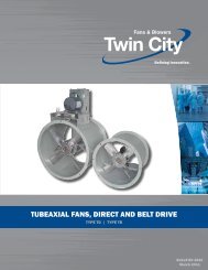
TYPE FA/FAB | TYPE WA/WAB | TYPE SA | TYPE HA/HAB | TYPE FR | TYPE MA<br />
BULLETIN <strong>3000</strong><br />
June 2011
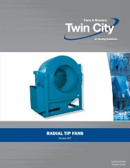
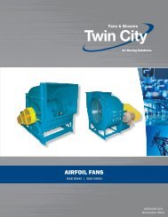
Fiber-Aire ® FA/FAB <strong>Fiberglass</strong> Roof <strong>Ventilators</strong><br />
Application<br />
The Fiber-Aire ® FA/FAB<br />
fiberglass centrifugal roof<br />
ventilator fans are available<br />
with direct drive<br />
or belt drive for general<br />
ventilation requirements<br />
where a low noise level<br />
exhaust is desired. The<br />
fiberglass housing of<br />
this fan is virtually dent,<br />
crack, and break proof<br />
and is highly resistant to a wide array of chemicals.<br />
The motor is completely separated from the<br />
airstream, as are the belts and drive components of<br />
the belt driven model.<br />
The fiberglass housing actually absorbs noise and<br />
vibration, and the specially molded throat and outlet<br />
designs minimize loss from friction and turbulence.<br />
Belt driven fans offer the versatility of changing air<br />
capacities by changing the sheaves during or after<br />
installation. Both direct drive and belt drive features<br />
have easy to remove motor covers for simple inspection<br />
and maintenance. Extra low contour makes them<br />
inconspicuous from street level.<br />
The Fiber-Aire ® series fiberglass centrifugal power<br />
roof ventilators are designed for the exhaust of<br />
moisture-laden, corrosive, or chemically contaminated<br />
air frequently associated with aquariums, indoor<br />
swimming pools, laboratories, waste water treatment<br />
plants, etc.<br />
Sizes and Capacities<br />
• Direct drive sizes 7" to 18"<br />
• Belt driven size 12" to 40"<br />
• Capacities from 150 CFM to 19,500 CFM<br />
• Static pressures to 1 3 ∕4" w.g.<br />
Construction Features<br />
• Molded fiberglass housings are virtually impossible<br />
to dent, crack, or break and resist weather, salt<br />
spray, and most chemicals. <strong>Fiberglass</strong> housings<br />
also absorb noise and vibration.<br />
• Designed for applications requiring the exhaust of<br />
chemical fumes or hazardous matter suspended in<br />
the air.<br />
• <strong>Fan</strong> wheel sizes 7, 9, 10, 12 and 40 are polypropylene,<br />
backward inclined, as standard.<br />
• <strong>Fan</strong> wheel sizes 14 through 36 are of an extruded<br />
aluminum airfoil, non-overloading type design,<br />
epoxy coated, as standard. A polypropylene wheel<br />
is optional.<br />
• Aluminum fan wheels and structural metal components<br />
in contact with airstream are epoxy coated<br />
for additional corrosion resistance.<br />
• A 1 ∕2" x 1 ∕2" PVC coated bird screen is standard<br />
on all units to prevent entry of birds and debris.<br />
• Factory mounted and wired disconnect switch is<br />
standard on all units, except with EXP motors.<br />
• Easy-to-remove motor covers for easy inspection<br />
and maintenance.<br />
• A conduit chase extending through the curb cap<br />
and into the motor compartment is provided as<br />
standard on all units for field supply conductors.<br />
• 304 SS shafts on belt drive unit.<br />
Accessories<br />
• Gravity (PVC) and motor operated (Aluminum)<br />
backdraft dampers<br />
• <strong>Fiberglass</strong> roof curbs<br />
• Special coatings and materials<br />
• Curb hinge<br />
Maximum <strong>Fan</strong> RPM<br />
MODEL<br />
NO.<br />
12FA * B<br />
14FA * B<br />
18FA * B<br />
24FA * B<br />
30FA*B<br />
MOTOR<br />
HP<br />
MAX FAN<br />
RPM<br />
1/4 1675<br />
1/3 1845<br />
1/2 2115<br />
1/4 1470<br />
1/3 1615<br />
1/2 1850<br />
1/4 905<br />
1/3 995<br />
1/2 1140<br />
1/4 570<br />
1/3 625<br />
1/2 720<br />
3/4 820<br />
1 905<br />
1/3 440<br />
1/2 500<br />
3/4 575<br />
1 630<br />
1 1 ⁄2 725<br />
2 795<br />
MODEL<br />
NO.<br />
36FA*B<br />
40FA * B<br />
MOTOR MAX FAN<br />
HP RPM<br />
1/2 370<br />
3/4 425<br />
1 465<br />
1 1 ⁄2 535<br />
2 585<br />
3 670<br />
1/2 320<br />
3/4 370<br />
1 405<br />
1 1 ⁄2 460<br />
2 510<br />
3 580<br />
5 690<br />
©2011 <strong>Twin</strong> <strong>City</strong> <strong>Fan</strong> Companies, Ltd. All rights reserved throughout the world.<br />
Bulletin illustrations cover the general appearance of <strong>Twin</strong> <strong>City</strong> <strong>Fan</strong> & <strong>Blower</strong> products at the time of publication<br />
and we reserve the right to make changes in design and construction at any time without notice.<br />
2 <strong>Twin</strong> <strong>City</strong> Bulletin <strong>3000</strong>
FA/FAB Performance Data<br />
Model FA – Direct Drive<br />
MODEL<br />
HP<br />
PEAK<br />
CFM VERSUS STATIC PRESSURE SOUND POWER REFERENCE 10 -12 WATTS SONES<br />
MTR<br />
AT 0"<br />
NO.<br />
BHP RPM 0" 1<br />
/8" 1<br />
/4" 3<br />
/8" 1<br />
/2" 5<br />
/8" 3<br />
OCTAVE BAND CENTER FREQUENCIES<br />
/4" 1"<br />
63 125 250 500 1000 2000 4000 8000 SP<br />
7FA1 1/15 0.06 1550 147 127 103 23 — — — — — — — — 14.6<br />
7FA2 1/15 0.09 1550 435 340 245 — — — — — — — — 9.1<br />
9FA1 1/15 0.08 1550 535 467 402 313 245 80 — — — — — — — — 13.8<br />
10FA1 1/8 0.06 1140 595 445 295 155 — — — — — — — — 9.3<br />
10FA2 1/6 0.19 1725 900 800 700 605 510 380 295 100 — — — — — — — — 14.9<br />
12FA1 1/12 0.03 860 682 570 362 72 73 66 59 54 48 43 41 6.2<br />
12FA2 1/8 0.07 1140 904 836 725 576 328 76 82 75 68 62 58 50 48 10.9<br />
12FA3 1/4 0.27 1725 1368 1329 1281 1220 1146 1059 963 733 84 87 88 81 75 69 64 58 20.0<br />
14FA1 1/12 0.05 860 1084 914 725 424 75 72 65 62 57 59 49 50 7.4<br />
14FA2 1/8 0.11 1140 1437 1308 1180 1040 861 658 82 81 73 70 64 65 61 54 12.2<br />
14FA3 1/2 0.40 1725 2175 2090 2004 1920 1835 1747 1656 1459 94 90 87 80 77 72 74 64 23.0<br />
18FA1 1/4 0.21 860 2361 2158 1944 1708 1387 885 75 80 81 76 69 64 56 50 13.5<br />
18FA2 1/2 0.49 1140 3129 2979 2822 2661 2318 2107 2107 1526 79 85 88 85 76 74 65 59 21.0<br />
1. Performance shown is for installation Type A: free inlet, free outlet.<br />
2. The sound power level ratings shown are in decibels, referred to 10 –12 watts calculated per AMCA Standard 301. Values shown are for Lwi sound<br />
power levels for installation Type A: free inlet, free outlet. Ratings do not include the effects of duct end correction for inlet and outlet ducts.<br />
3. Performance ratings do not include the effects of appurtenances in the airstream.<br />
Model FAB – Belt Driven<br />
CFM VERSUS STATIC PRESSURE SOUND POWER REFERENCE 10 -12 WATTS SONES<br />
MODEL PEAK FAN<br />
HP<br />
AT 0"<br />
NO.<br />
BHP RPM 0" 1<br />
/8" 1<br />
/4" 3<br />
/8" 1<br />
/2" 5<br />
/8" 3<br />
OCTAVE BAND CENTER FREQUENCIES<br />
/4" 1" 1 1 /4" 1 1 /2" 1 3 /4"<br />
63 125 250 500 1000 2000 4000 8000 SP<br />
12FA1B 1/4 0.12 1331 1055 1001 922 815 684 521 82 76 73 66 63 63 53 52 10.0<br />
12FA2B 1/4 0.16 1465 1162 1114 1049 962 856 733 583 84 78 75 68 65 65 58 54 11.5<br />
12FA3B 1/4 0.25 1676 1329 1298 1238 1174 1094 1002 900 644 84 87 87 80 74 69 62 58 19.4<br />
12FA4B 1/3 0.33 1844 1462 1426 1383 1330 1266 1192 1108 915 791 653 86 88 90 83 77 71 66 60 23.0<br />
12FA5B 1/2 0.50 2112 1675 1644 1609 1568 1520 1465 1403 1259 1094 898 575 89 89 94 88 81 75 70 63 29.0<br />
14FA1B 1/4 0.12 1166 1470 1344 1219 1083 933 735 83 82 73 70 65 65 62 55 12.8<br />
14FA2B 1/4 0.16 1283 1618 1503 1389 1271 1144 1002 821 86 84 76 73 68 66 65 57 14.9<br />
14FA3B 1/4 0.25 1468 1851 1750 1651 1551 1447 1336 1217 911 1230 870 90 87 81 76 72 68 70 59 18.5<br />
14FA4B 1/3 0.33 1616 2037 1946 1855 1766 1674 1577 1476 1254 92 90 85 79 76 70 74 61 22.0<br />
14FA5B 1/2 0.50 1850 2332 2253 2173 2095 2016 1936 1852 1678 96 92 90 82 79 76 76 67 27.0<br />
18FA1B 1/4 0.16 790 2169 1946 1710 1418 969 74 79 79 72 67 61 54 48 11.8<br />
18FA2B 1/4 0.25 905 2484 2292 2090 1875 1605 1230 373 76 81 82 77 71 66 58 52 14.6<br />
18FA3B 1/3 0.33 993 2726 2552 2369 2181 1972 1708 1359 77 83 85 80 73 69 61 55 17.2<br />
18FA4B 1/2 0.50 1140 3129 2979 2822 2661 2496 2318 2107 1526 79 85 88 85 76 73 65 59 21.0<br />
24FA1B 1/4 0.16 496 3341 2809 2132 981 72 72 67 61 57 53 44 46 6.6<br />
24FA2B 1/4 0.25 568 3825 3367 2842 2158 980 75 75 71 64 60 56 47 49 8.2<br />
24FA3B 1/3 0.33 625 4209 3794 3344 2795 2078 526 77 77 74 67 63 59 49 51 9.6<br />
24FA4B 1/2 0.50 716 4822 4461 4088 3666 3172 2562 1725 80 80 78 72 67 63 53 53 12.2<br />
24FA5B 3/4 0.75 819 5516 5201 4880 4542 4163 3732 3241 1827 82 84 82 76 71 67 59 56 15.5<br />
24FA6B 1 1.0 902 6075 5791 5499 5204 4884 4528 4139 3189 1671 83 86 85 79 79 69 64 57 18.8<br />
30FA1B 1/3 0.33 436 5703 4962 4135 3003 75 76 72 68 62 55 49 50 8.8<br />
30FA2B 1/2 0.50 500 6540 5900 5219 4430 3372 1063 78 79 77 72 66 59 53 52 11.4<br />
30FA3B 3/4 0.75 572 7482 6926 6345 5725 5003 4103 2946 81 82 81 76 70 63 57 55 14.3<br />
30FA4B 1 1.0 630 8240 7738 7217 6673 6087 5408 4577 83 84 83 78 72 66 60 57 16.4<br />
30FA5B 1 1 ⁄2 1.5 721 9431 8993 8545 8082 7603 7095 6528 5128 3035 88 87 87 82 76 71 64 60 21.0<br />
30FA6B 2 2.0 793 10372 9974 9570 9155 8729 8290 7828 6758 5397 3501 91 88 89 84 80 74 67 62 24.0<br />
36FA1B 1/2 0.50 369 8644 7438 6135 4579 82 78 73 63 61 54 50 50 9.4<br />
36FA2B 3/4 0.75 422 9885 8839 7738 6541 5097 2348 86 81 78 67 64 59 53 53 12.1<br />
36FA3B 1 1.0 464 10869 9922 8937 7893 6751 5350 2853 89 84 82 70 67 62 56 54 14.8<br />
36FA4B 1 1 ⁄2 1.5 523 12462 11643 10792 9916 8996 8013 6893 2648 92 87 85 75 70 67 59 57 18.1<br />
36FA5B 2 2.0 585 13704 12964 12194 11413 10599 9753 8854 6659 94 90 87 79 72 70 62 59 21.0<br />
36FA6B 3 3.0 670 15695 15056 14386 13708 13022 12317 11587 10030 8191 5346 97 94 92 84 76 74 66 63 27.0<br />
40FA1B 1/2 0.50 320 9061 7681 6024 3256 75 72 67 59 56 51 49 44 6.7<br />
40FA2B 3/4 0.75 366 10363 9157 7878 6129 3433 79 75 72 63 60 55 52 48 8.6<br />
40FA3B 1 1.0 403 11411 10315 9200 7863 6009 2995 83 77 76 66 63 58 54 51 10.6<br />
40FA4B 1 1 ⁄2 1.5 461 13053 12095 11136 10116 8893 7302 5303 87 81 80 70 66 62 57 55 13.5<br />
40FA5B 2 2.0 508 14384 13516 12648 11760 10788 9619 8159 3505 89 84 82 74 68 65 60 58 15.8<br />
40FA6B 3 3.0 581 16451 15693 14932 14173 13392 12544 11580 9125 5655 92 87 83 79 71 68 63 61 18.7<br />
40FA7B 5 5.0 689 19509 18873 18227 17589 16949 16301 15623 14114 12224 9907 7200 96 93 89 85 76 73 68 65 26.0<br />
1. Performance shown is for installation Type A: free inlet, free outlet.<br />
2. The sound power level ratings shown are in decibels, referred to 10 –12 watts calculated per AMCA Standard 301. Values shown are for Lwi<br />
sound power levels for installation Type A: free inlet, free outlet. Ratings do not include the effects of duct end correction for inlet and<br />
outlet ducts.<br />
3. Power rating (BHP) does not include drive losses.<br />
4. Performance ratings do not include the effects of appurtenances in the airstream.<br />
3 <strong>Twin</strong> <strong>City</strong> Bulletin <strong>3000</strong>
FA/FAB Dimensional Data<br />
Baffle<br />
E<br />
Model FA - Direct Drive<br />
D Dia.<br />
Top Cap<br />
Baf fle<br />
E<br />
Model FAB - Belt Drive<br />
D Dia.<br />
T op Cap<br />
Mounting<br />
Plate<br />
Base<br />
F<br />
Base<br />
A Sq.<br />
Roof Opening<br />
B Sq.<br />
Model FA - Direct Drive<br />
4"<br />
Curb O.D.<br />
C<br />
5 /8"<br />
F<br />
Anchor Bolt<br />
(By Others)<br />
Dampers (Optional)<br />
Roof Opening<br />
A Sq.<br />
4"<br />
B Sq.<br />
Curb O.D.<br />
MODEL NO. HP RPM<br />
WEIGHT<br />
DIMENSIONS (INCHES)<br />
BACKDRAFT<br />
(LBS.)<br />
A B C D E F DAMPER<br />
7FA1 1/15 1550 23<br />
12 20 2 21 3 3<br />
⁄8 10<br />
⁄16<br />
7FA2 1/15 1550 20 2 11 ⁄16<br />
10 x 10<br />
9FA1 1/15 1550 24 12 20 2 21 3 ⁄8 10 2 1 ⁄2 10 x 10<br />
10FA1 1/8 1140 43<br />
10FA2 1/6 1725 39<br />
16 24 2 3 ⁄4 28 1 ⁄4 15 1 ⁄2 3 1 ⁄4 14 x 14<br />
12FA1 1/12 860 43<br />
12FA2 1/8 1140 45<br />
16 24 2 3 ⁄4 28 1 ⁄4 15 1 ⁄2 2 1 ⁄8 14 x 14<br />
12FA3 1/4 1725 49<br />
14FA1 1/12 860 51<br />
14FA2 1/8 1140 50<br />
16 24 2 3 ⁄4 28 1 ⁄4 15 1 ⁄2 4 5 ⁄8 14 x 14<br />
14FA3 1/2 1725 49<br />
18FA1 1/4 860 78<br />
18FA2 1/2 1140 83<br />
20 28 3 1 ⁄8 35 1 ⁄8 21 3 ⁄4 4 3 ⁄4 18 x 18<br />
C<br />
5/8"<br />
Model FAB - Belt Driven<br />
MODEL NO. HP<br />
WEIGHT<br />
(LBS.)<br />
12FA1B 1/4 42<br />
12FA2B 1/4 42<br />
12FA3B 1/4 42<br />
12FA4B 1/3 44<br />
12FA5B 1/2 49<br />
14FA1B 1/4 44<br />
14FA2B 1/4 44<br />
14FA3B 1/4 47<br />
14FA4B 1/3 46<br />
14FA5B 1/2 51<br />
18FA1B 1/4 69<br />
18FA2B 1/4 70<br />
18FA3B 1/3 70<br />
18FA4B 1/2 76<br />
24FA1B 1/4 142<br />
24FA2B 1/4 144<br />
24FA3B 1/3 143<br />
24FA4B 1/2 148<br />
24FA5B 3/4 154<br />
24FA6B 1 176<br />
30FA1B 1/3 188<br />
30FA2B 1/2 193<br />
30FA3B 3/4 202<br />
30FA4B 1 210<br />
30FA5B 1 1 ⁄2 235<br />
30FA6B 2 236<br />
36FA1B 1/2 258<br />
36FA2B 3/4 261<br />
36FA3B 1 285<br />
36FA4B 1 1 ⁄2 296<br />
36FA5B 2 297<br />
36FA6B 3 329<br />
40FA1B 1/2 353<br />
40FA2B 3/4 356<br />
40FA3B 1 370<br />
40FA4B 1 1 ⁄2 379<br />
40FA5B 2 380<br />
40FA6B 3 405<br />
40FA7B 5 454<br />
DIMENSIONS (INCHES)<br />
A B C D E F<br />
BACKDRAFT<br />
DAMPER<br />
16 24 2 3 ⁄4 28 1 ⁄4 23 3 ⁄8 2 1 ⁄8 14 x 14<br />
16 24 2 3 ⁄4 28 1 ⁄4 23 3 ⁄8 4 5 ⁄8 14 x 14<br />
20 28 3 1 ⁄8 35 1 ⁄8 25 3 ⁄4 4 3 ⁄4 18 x 18<br />
28 36 3 42 13 ⁄16 26 5 1 ⁄4 24 x 24<br />
36 44 3 53 5 ⁄16 31 1 ⁄2 6 30 x 30<br />
44 52 3 62 1 ⁄2 34 3 ⁄4 8 1 ⁄2 36 x 36<br />
44 52 3 62 1 ⁄2 34 3 ⁄4 8 1 ⁄2 36 x 36<br />
4 <strong>Twin</strong> <strong>City</strong> Bulletin <strong>3000</strong>
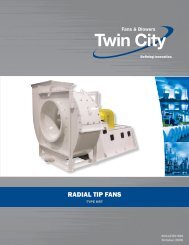
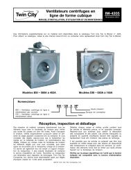
Whirlout ® WA/WAB <strong>Fiberglass</strong> Roof Exhausters<br />
Application<br />
The Whirlout ® Series<br />
WA/WAB fiberglass<br />
up-blast centrifugal<br />
roof exhausters<br />
are especially<br />
designed for applications<br />
requiring the<br />
exhaust of chemical<br />
fumes or cooking<br />
grease where the<br />
removal of exhaust<br />
away from the roof<br />
line is required.<br />
<strong>Fiberglass</strong> roof exhausters are available as direct<br />
or adjustable capacity belt drive. Each configuration<br />
features an isolated motor and drive chamber with<br />
a neoprene shaft seal to protect motor and drive<br />
components from fumes or hazardous matter suspended<br />
in the air. The upblast design makes it ideal<br />
for use with ducts, hoods or canopies over interior<br />
work areas. Basket type supports eliminate internal<br />
air shocks, reduce vibration and increase efficiency.<br />
The fiberglass housing of the unit has excellent<br />
resistance to a wide range of chemicals and fumes<br />
and can withstand temperatures as high as 150°F<br />
when high temperature motors are used (special<br />
order). The powerful corrosion resistant, airfoil design<br />
wheel provides quiet and efficient operation. <strong>Fan</strong><br />
wheels are constructed of extruded aluminum, epoxy<br />
coated blades as standard on sizes 14 through 36.<br />
A polypropylene option provides additional corrosion<br />
resistance, and is standard on sizes 7, 10, 12 and 40.<br />
Whirlout ® Series fiberglass upblast centrifugal roof<br />
exhausters are also used in natatoriums, aquariums,<br />
indoor swimming pools, laboratories, waste water<br />
treatment plants, and any other area, where corrosive<br />
fumes present a problem.<br />
Construction Features<br />
• Molded fiberglass housings are virtually impossible<br />
to dent, crack, or break, and resist weather, salt<br />
spray, and most chemicals. <strong>Fiberglass</strong> housings<br />
also absorb noise and vibration.<br />
• Designed for applications requiring the exhaust of<br />
chemical fumes or contaminated air up and away<br />
from the roof.<br />
• A neoprene shaft seal is standard on all belt drive<br />
units to protect motor and drives from fumes or<br />
hazardous matter suspended in the air.<br />
• Ideal for use with ducts, hoods, or canopies over<br />
interior work areas.<br />
• <strong>Fiberglass</strong> housing withstands temperatures up to<br />
150°F. Polypropylene wheels up to 104°F.<br />
• Factory mounted and wired disconnect switch is<br />
standard on all units, except with EXP motors.<br />
• <strong>Fan</strong> wheels, sizes 7, 10, 12 and 40 feature a<br />
polypropylene, non-overloading backward inclined<br />
design.<br />
• <strong>Fan</strong> wheels, sizes 14 through 36, feature an<br />
extruded aluminum, non-overloading, airfoil design,<br />
epoxy coated as standard. A polypropylene wheel<br />
is optional.<br />
• Aluminum fan wheels and structural metal components<br />
in contact with airstream are epoxy coated<br />
for additional corrosion resistance.<br />
• A conduit chase extending through the curb cap<br />
and into the motor compartment is provided as<br />
standard on all units for field wiring.<br />
• 304 SS shaft on belt drive unit.<br />
Accessories<br />
• Gravity (PVC) and motorized (Aluminum) backdraft<br />
dampers<br />
<strong>Fiberglass</strong> roof curbs<br />
Bird screen<br />
• Curb hinge<br />
Sizes and Capacities<br />
• Direct drive sizes 7" to 18"<br />
• Belt driven sizes 14" to 40"<br />
• Capacities from 370 CFM to 21,500 CFM<br />
• Static pressures to 2" w.g.<br />
Maximum <strong>Fan</strong> RPM<br />
MODEL<br />
NO.<br />
14WA * B<br />
18WA * B<br />
24WA * B<br />
30WA * B<br />
MOTOR<br />
HP<br />
MAX FAN<br />
RPM<br />
1/4 1475<br />
1/3 1635<br />
1/2 1870<br />
1/4 900<br />
1/3 990<br />
1/2 1130<br />
1/4 560<br />
1/3 615<br />
1/2 705<br />
3/4 805<br />
1 890<br />
1/3 435<br />
1/2 500<br />
3/4 570<br />
1 630<br />
1 1 ⁄2 720<br />
2 790<br />
MODEL<br />
NO.<br />
36WA*B<br />
40WA*B<br />
MOTOR MAX FAN<br />
HP RPM<br />
1/2 365<br />
3/4 415<br />
1 460<br />
1 1 ⁄2 525<br />
2 580<br />
3 660<br />
5 785<br />
1/2 315<br />
3/4 360<br />
1 395<br />
1 1 ⁄2 450<br />
2 495<br />
3 565<br />
5 675<br />
7 1 ⁄2 765<br />
5 <strong>Twin</strong> <strong>City</strong> Bulletin <strong>3000</strong>
WA/WAB Performance Data<br />
Model WA – Direct Drive<br />
MODEL<br />
NO.<br />
HP<br />
PEAK<br />
BHP<br />
MTR<br />
RPM<br />
CFM VERSUS STATIC PRESSURE SOUND POWER REFERENCE 10 -12 WATTS SONES<br />
AT 0"<br />
0" 1<br />
/8" 1<br />
/4" 3<br />
/8" 1<br />
/2" 5<br />
/8" 3<br />
OCTAVE BAND CENTER FREQUENCIES<br />
/4" 1"<br />
63 125 250 500 1000 2000 4000 8000 SP<br />
7WA2 1/15 0.04 1550 370 355 290 140 — — — — — — — — 2.5<br />
10WA1 1/12 0.02 860 600 465 200 — — — — — — — — 2.2<br />
10WA2 1/8 0.05 1140 800 700 580 420 50 — — — — — — — — 3.7<br />
10WA3 1/6 0.18 1725 1210 1145 1080 1005 930 845 740 370 — — — — — — — — 7.2<br />
12WA1 1/12 0.03 860 648 498 263 74 69 65 63 59 58 50 48 7.1<br />
12WA2 1/8 0.07 1140 859 751 628 464 82 77 73 71 67 64 60 54 11.3<br />
12WA3 1/4 0.26 1725 1300 1229 1157 1082 1002 911 808 536 93 89 84 81 78 74 73 65 23.0<br />
14WA1 1/12 0.06 860 1060 883 658 298 73 72 68 64 60 60 48 50 7.7<br />
14WA2 1/8 0.13 1140 1405 1276 1135 970 768 501 79 81 76 72 67 67 60 54 12.6<br />
14WA3 1/2 0.45 1725 2127 2041 1955 1867 1774 1675 1568 1326 88 88 87 83 79 75 75 63 23.0<br />
18WA1 1/4 0.17 860 2011 1796 1566 1288 926 81 79 76 71 66 63 56 53 11.6<br />
18WA2 1/2 0.39 1140 2665 2505 2340 2170 1982 1770 1527 900 87 87 84 80 74 71 65 60 18.9<br />
1. Performance shown is for installation Type A: free inlet, free outlet.<br />
2. The sound power level ratings shown are in decibels, referred to 10 -12 watts calculated per AMCA Standard 301. Values<br />
shown are for Lwi sound power levels for installation Type A: free inlet, free outlet. Ratings do not include the effects of<br />
duct end correction for inlet and outlet ducts.<br />
3. Performance ratings do not include the effects of appurtenances in the airstream.<br />
Model WAB – Belt Driven<br />
MODEL<br />
HP<br />
PEAK<br />
CFM VERSUS STATIC PRESSURE SOUND POWER REFERENCE 10 -12 WATTS SONES<br />
FAN<br />
AT 0"<br />
NO.<br />
BHP RPM 0" 1<br />
/8" 1<br />
/4" 3<br />
/8" 1<br />
/2" 5<br />
/8" 3<br />
OCTAVE BAND CENTER FREQUENCIES<br />
/4" 1" 1 1 /4" 1 1 /2" 1 3 /4" 2"<br />
63 125 250 500 1000 2000 4000 8000 SP<br />
14WA1B 1/4 0.12 1125 1387 1255 1112 943 732 442 78 80 75 71 67 66 59 54 1 1 . 9<br />
14WA2B 1/4 0.16 1238 1526 1406 1281 1137 973 772 507 80 82 78 74 70 68 64 55 14.0<br />
14WA3B 1/4 0.25 1418 1748 1644 1539 1423 1299 1155 989 538 83 85 82 78 74 71 69 59 17.6<br />
14WA4B 1/3 0.33 1560 1923 1832 1733 1632 1522 1406 1276 962 480 85 87 84 81 76 73 72 60 20.0<br />
14WA5B 1/2 0.50 1786 2201 2118 2037 1952 1864 1768 1664 1441 1185 850 205 88 89 88 84 80 75 75 64 24.0<br />
18WA1B 1/4 0.16 784 2084 1822 1521 1130 488 79 77 74 68 64 61 53 51 10.0<br />
18WA2B 1/4 0.25 898 2387 2160 1915 1626 1268 753 82 81 78 73 67 65 58 54 12.9<br />
18WA3B 1/3 0.33 988 2626 2420 2205 1964 1678 1334 858 83 84 81 77 70 68 61 56 15.4<br />
18WA4B 1/2 0.50 1131 3007 2827 2643 2448 2231 1987 1705 911 86 87 84 80 73 71 65 59 18.7<br />
24WA1B 1/4 0.16 488 3167 2603 1811 82 75 70 65 61 53 47 47 8.5<br />
24WA2B 1/4 0.25 559 3628 3146 2562 1735 84 80 73 68 64 58 50 50 10.7<br />
24WA3B 1/3 0.33 615 3992 3557 3067 2420 1567 86 83 76 71 66 61 52 52 12.9<br />
24WA4B 1/2 0.50 704 4569 4195 3791 3320 2720 1992 88 88 80 75 70 66 57 55 16.8<br />
24WA5B 3/4 0.75 806 5231 4910 4563 4195 3768 3253 2656 89 93 84 79 74 70 62 57 21.0<br />
24WA6B 1 1.00 887 5757 5469 5155 4834 4484 4079 3607 2465 91 95 87 82 77 73 65 60 25.0<br />
30WA1B 1/3 0.33 434 5284 4557 3690 2419 81 79 73 67 64 56 52 49 10.0<br />
30WA2B 1/2 0.50 497 6051 5424 4730 3886 2666 85 82 79 70 69 60 56 52 13.0<br />
30WA3B 3/4 0.75 569 6927 6384 5807 5158 4389 3377 88 86 82 74 73 65 59 56 16.5<br />
30WA4B 1 1.00 627 7634 7143 6629 6074 5451 4723 3805 90 88 84 79 75 69 61 58 19.0<br />
30WA5B 1 1 ⁄2 1.50 717 8729 8302 7861 7399 6908 6366 5763 4201 92 92 88 81 78 73 65 62 23.0<br />
30WA6B 2 2.00 790 9618 9231 8835 8427 7999 7544 7048 5914 4343 94 94 92 85 80 76 68 64 28.0<br />
36WA1B 1/2 0.50 363 8226 7108 5681 3663 84 79 73 65 64 55 50 49 10.0<br />
36WA2B 3/4 0.75 416 9428 8477 7347 5944 4006 87 83 78 69 67 60 54 51 13.1<br />
36WA3B 1 1.00 458 10379 9528 8551 7403 6001 4136 89 86 81 72 70 63 56 52 15.5<br />
36WA4B 1 1 ⁄2 1.50 524 11875 11143 10333 9426 8387 7181 5715 91 90 85 77 73 68 60 55 19.5<br />
36WA5B 2 2.00 577 13076 12417 11702 10921 10052 9082 7979 5087 93 92 88 80 75 72 63 58 23.0<br />
36WA6B 3 3.00 660 14957 14388 13780 13131 12433 11685 10867 8974 6544 96 96 92 84 78 76 67 62 28.0<br />
36WA7B 5 5.00 782 17722 17230 16761 16235 15688 15100 14432 13157 11650 9900 7899 4032 101 101 96 91 82 81 73 67 39.0<br />
40WA1B 1/2 0.50 312 8795 7263 5263 1099 84 79 74 65 64 57 54 52 10.5<br />
40WA2B 3/4 0.75 357 10064 8756 7170 5189 88 82 78 70 67 61 57 55 13.2<br />
40WA3B 1 1.00 393 11078 9899 8555 6941 4778 90 84 80 73 69 63 59 57 15.2<br />
40WA4B 1 1 ⁄2 1.50 450 12685 11657 10569 9286 7839 6065 2894 92 88 84 77 73 67 62 60 18.9<br />
40WA5B 2 2.00 495 13954 13019 12062 10983 9746 8394 6759 94 90 87 80 75 69 64 62 22.0<br />
40WA6B 3 3.00 567 15983 15164 14351 13480 12512 11438 10302 7517 96 94 92 85 80 73 68 66 28.0<br />
40WA7B 5 5.00 672 18943 18249 17567 16871 16139 15354 14496 12624 10537 7607 2000 98 99 96 91 84 78 73 70 37.0<br />
40WA8B 7 1 ⁄2 7.50 763 21508 20922 20300 19689 19092 18430 17748 16235 14586 12776 10788 7690 100 102 99 94 87 82 76 73 44.0<br />
1. Performance shown is for installation Type A: free inlet, free outlet.<br />
2. The sound power level ratings shown are in decibels, referred to 10 -12 watts calculated per AMCA Standard 301. Values shown are for Lwi sound<br />
power levels for installation Type A: free inlet, free outlet. Ratings do not include the effects of duct end correction for inlet and outlet ducts.<br />
3. Power rating (BHP) does not include drive losses.<br />
4. Performance ratings do not include the effects of appurtenances in the airstream.<br />
6 <strong>Twin</strong> <strong>City</strong> Bulletin <strong>3000</strong>
WA/WAB Dimensional Data<br />
Model WA - Direct Drive<br />
Model WAB - Belt Driven<br />
Bird<br />
Screen<br />
D<br />
Bird Screen<br />
D<br />
F<br />
E<br />
Cooling<br />
Tube<br />
F<br />
E<br />
Cooling<br />
Tube<br />
C<br />
Roof Opening<br />
A<br />
Model WA - Direct Drive<br />
Conduit<br />
Tube<br />
0.63 B<br />
0.63<br />
Curb O.D.<br />
C<br />
Conduit<br />
Tube<br />
Roof Opening<br />
A<br />
0.63 B<br />
0.63<br />
Curb O.D.<br />
MODEL NO. HP RPM<br />
WEIGHT<br />
DIMENSIONS (INCHES)<br />
BACKDRAFT<br />
(LBS.)<br />
A B C D E F DAMPER<br />
7WA2 1/15 1550 18 8 16 2 17 1 ⁄4 8 10 1 ⁄2 6 x 6<br />
10WA1 1/12 860 50<br />
10WA2 1/8 1140 43<br />
12 20 3 25 1 ⁄4 12 1 ⁄8 18 1 ⁄4 10 x 10<br />
10WA3 1/6 1725 44<br />
12WA1 1/12 860 50<br />
12WA2 1/8 1140 43<br />
12 20 3 25 1 ⁄4 12 1 ⁄8 18 3 ⁄4 10 x 10<br />
12WA3 1/4 1725 46<br />
14WA1 1/12 860 67<br />
14WA2 1/8 1140 67<br />
16 24 3 28 7 ⁄8 17 1 ⁄2 19 3 ⁄4 14 x 14<br />
14WA3 1/2 1725 73<br />
18WA1 1/4 860 118<br />
18WA2 1/2 1140 130<br />
20 28 3 36 3 ⁄4 25 26 3 ⁄4 18 x 18<br />
D-3300-1A<br />
Model WAB - Belt Driven<br />
MODEL NO. HP<br />
WEIGHT<br />
(LBS.)<br />
14WA1B 1/4 72<br />
14WA2B 1/4 73<br />
14WA3B 1/4 75<br />
14WA4B 1/3 74<br />
14WA5B 1/2 76<br />
18WA1B 1/4 123<br />
18WA2B 1/4 125<br />
18WA3B 1/3 129<br />
18WA4B 1/2 133<br />
24WA1B 1/4 185<br />
24WA2B 1/4 187<br />
24WA3B 1/3 192<br />
24WA4B 1/2 195<br />
24WA5B 3/4 202<br />
24WA6B 1 205<br />
30WA1B 1/3 265<br />
30WA2B 1/2 269<br />
30WA3B 3/4 287<br />
30WA4B 1 291<br />
30WA5B 1 1 ⁄2 295<br />
30WA6B 2 307<br />
36WA1B 1/2 572<br />
36WA2B 3/4 591<br />
36WA3B 1 595<br />
36WA4B 1 1 ⁄2 599<br />
36WA5B 2 611<br />
36WA6B 3 615<br />
36WA7B 5 625<br />
40WA1B 1/2 632<br />
40WA2B 3/4 658<br />
40WA3B 1 675<br />
40WA4B 1 1 ⁄2 671<br />
40WA5B 2 677<br />
40WA6B 3 681<br />
40WA7B 5 730<br />
40WA8B 7 1 ⁄2 750<br />
DIMENSIONS (INCHES)<br />
A B C D E F<br />
BACKDRAFT<br />
DAMPER<br />
16 24 3 28 7 ⁄8 17 1 ⁄2 27 1 ⁄2 14 x 14<br />
20 28 3 36 3 ⁄4 25 31 1 ⁄4 18 x 18<br />
28 36 3 45 3 ⁄4 31 32 1 ⁄2 24 x 24<br />
36 44 3 59 34 1 ⁄2 37 30 x 30<br />
44 52 3 69 1 ⁄2 45 43 1 ⁄2 36 x 36<br />
44 52 3 69 1 ⁄2 45 43 1 ⁄2 36 x 36<br />
D-3300-2A<br />
7 <strong>Twin</strong> <strong>City</strong> Bulletin <strong>3000</strong>
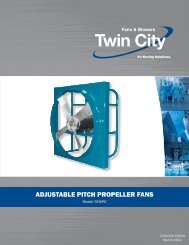
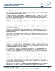
Fiber-Aire ® SA <strong>Fiberglass</strong> Wall Exhausters<br />
Application<br />
The Fiber-Aire ® Series SA fiberglass<br />
wall ventilators are ideal<br />
for applications where exhausting<br />
from the roof is impractical<br />
or impossible. Featuring<br />
the same high-volume, extruded<br />
aluminum, epoxy coated airfoil<br />
wheel as the standard Fiber-<br />
Aire ® , the wall Fiber-Aire ® effectively<br />
and efficiently pulls hazardous<br />
fumes, dust, or corrosive<br />
gases from the building interior and exhausts them<br />
away from the building and the exterior wall.<br />
The wall Fiber-Aire ® Series features the same virtually<br />
indestructible fiberglass housing, which is completely<br />
weatherproof and isolates the motor from the<br />
airstream. Its quiet operation allows the wall Fiber-<br />
Aire® to be placed in close proximity to work areas<br />
for maximum exhaust benefits and worker comfort.<br />
The exterior design and molded-in beige color blend<br />
in with most brick and exterior wall colors without<br />
detracting from overall building appearance. Wall<br />
shutters are available as accessories.<br />
These fiberglass centrifugal ventilators are used<br />
in natatoriums, aquariums, indoor swimming pools,<br />
laboratories, and waste water treatment plants.<br />
Model SA – Direct Drive<br />
Sizes and Capacities<br />
• Direct drive sizes 7" to 14"<br />
• Capacities from 235 CFM to 2,230 CFM<br />
• Static pressures to 1" w.g.<br />
Construction Features<br />
• Molded fiberglass housings are virtually impossible<br />
to dent, crack or break and resist weather, salt<br />
spray, and most chemicals. <strong>Fiberglass</strong> housings<br />
also absorb noise and vibration.<br />
• Designed for applications requiring the exhaust of<br />
chemical fumes or hazardous matter suspended in<br />
the air.<br />
• <strong>Fan</strong> wheel sizes 7 and 12 are polypropylene as<br />
standard.<br />
• <strong>Fan</strong> wheel size 14 is of an extruded aluminum<br />
airfoil epoxy coated, backwardly inclined, non-overloading<br />
type design.<br />
• A PVC coated bird screen is standard on all<br />
units.<br />
• Factory mounted and wired disconnect switch is<br />
standard on all units, except with EXP motors.<br />
• Designed for applications where exhausting from<br />
the roof is impractical or impossible.<br />
• A conduit chase is provided as standard to allow<br />
field electrical wiring from inside the building,<br />
through the fiberglass inlet venturi, and to the<br />
disconnect switch.<br />
MODEL<br />
HP<br />
PEAK<br />
CFM VERSUS STATIC PRESSURE SOUND POWER REFERENCE 10 -12 WATTS SONES<br />
FAN<br />
AT 0"<br />
NO.<br />
BHP RPM 0" 1<br />
/8" 1<br />
/4" 3<br />
/8" 1<br />
/2" 5<br />
/8" 3<br />
OCTAVE BAND CENTER FREQUENCIES<br />
/4" 1"<br />
63 125 250 500 1000 2000 4000 6000 SP<br />
7SA 1/15 0.02 1550 235 180 120 — — — — — — — — 4.6<br />
7SA2 1/15 0.03 1550 360 290 190 — — — — — — — — 6.1<br />
12SA1 1/12 0.03 860 652 502 296 71 60 59 59 56 56 45 48 5.7<br />
12SA2 1/8 0.06 1140 864 756 634 497 78 71 65 65 65 62 56 52 8.9<br />
12SA3 1/4 0.20 1725 1308 1238 1165 1090 1009 923 837 603 87 86 75 74 74 71 71 60 17.6<br />
14SA1 1/12 0.06 860 1112 960 754 438 77 74 66 65 60 59 48 50 7.9<br />
14SA2 1/8 0.15 1140 1474 1365 1241 1090 906 668 295 82 85 72 72 68 66 58 54 14.0<br />
14SA3 1/2 0.51 1725 2230 2161 2087 2010 1929 1840 1742 1517 95 91 89 87 80 75 74 63 27.0<br />
1. Performance shown is for installation Type A: free inlet, free outlet.<br />
2. The sound power level ratings shown are in decibels, referred to 10 –12 watts calculated per AMCA Standard 301. Values shown are for Lwi sound<br />
power levels for installation Type A: free inlet, free outlet. Ratings do not include the effects of duct end correction for inlet and outlet ducts.<br />
3. Performance ratings do not include the effects of appurtenances in the airstream.<br />
D<br />
C<br />
Model SA - Direct Drive<br />
A Sq.<br />
Opening<br />
Bird<br />
Screen<br />
B Dia<br />
MODEL<br />
FAN<br />
DIMENSIONS (INCHES)<br />
NET WT.<br />
HP<br />
NO.<br />
RPM A B C D<br />
(LBS.)<br />
7SA1 1/15 1550 10 19 1 ⁄2 9 3 ⁄4 1 1 ⁄2 15<br />
7SA2 1/15 1550 10 19 1 ⁄2 9 3 ⁄4 1 1 ⁄2 15<br />
12SA1 1/12 860 17 28 15 3 1 ⁄2 45<br />
12SA2 1/8 1140 17 28 15 3 1 ⁄2 43<br />
12SA3 1/4 1725 17 28 15 3 1 ⁄2 45<br />
14SA1 1/12 860 24 36 1 ⁄2 18 1 ⁄2 5 78<br />
14SA2 1/8 1140 24 36 1 ⁄2 18 1 ⁄2 5 78<br />
14SA3 1/2 1725 24 36 1 ⁄2 18 1 ⁄2 5 80<br />
BACKDRAFT<br />
DAMPER*<br />
10 x 10<br />
17 x 17<br />
24 x 24<br />
* PVC damper to have 7 ⁄8" flanges. Aluminum damper to have 1 3 ⁄8" flanges.<br />
Wall<br />
Cooling Tubes<br />
8 <strong>Twin</strong> <strong>City</strong> Bulletin <strong>3000</strong>
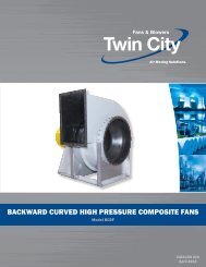
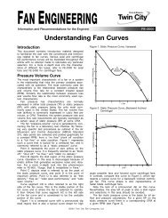
Hid-N-Aire ® HA/HAB <strong>Fiberglass</strong> Wall <strong>Ventilators</strong><br />
Application<br />
The Hid-N-Aire ® , Type HA/<br />
HAB, fiberglass wall mount<br />
ventilators provide high<br />
performance ventilation<br />
without distracting from<br />
the architectural lines of<br />
a building’s exterior. Only<br />
the aluminum fixed louver,<br />
which fits flush with the<br />
building’s wall, is visible<br />
from the outside of the<br />
building. From the interior,<br />
the unit presents a clean, molded fiberglass venturi.<br />
All fiberglass components come in the standard beige<br />
color.<br />
The Hid-N-Aire ® fiberglass centrifugal wall ventilators<br />
are designed to mount compactly within an<br />
exterior wall and satisfy general building exhaust<br />
requirements.<br />
Sizes and Capacities<br />
• Direct drive sizes 7" to 18"<br />
• Belt driven sizes 12" to 30"<br />
• Capacities from 180 CFM to 9,800 CFM<br />
• Static pressures to 1" w.g.<br />
Construction Features<br />
• Extruded fixed aluminum louver fits flush with the<br />
building’s wall and is visible only from the exterior.<br />
• <strong>Fan</strong> wheel sizes 7, 10 and 12 are polypropylene<br />
as standard.<br />
• Both belt and direct drive models (sizes 14 through<br />
30) feature an extruded aluminum, epoxy-coated,<br />
non-overloading airfoil fan wheel, as standard. A<br />
polypropylene wheel is optional.<br />
• Rugged molded fiberglass inlet venturi.<br />
• Rubber isolator motor mounts absorb vibration for<br />
quietness.<br />
• Built-in PVC bird screen and fabric backdraft<br />
dampers within aluminum louver.<br />
• Simple to install and maintain.<br />
• Motor is prewired with plug and cord assembly<br />
and provided with a plug-in electrical receptacle<br />
mounted inside the motor housing for ease of<br />
maintenance and service.<br />
• 304 SS shaft on belt drive unit.<br />
Accessories<br />
• An attractive grille is available for attachment to<br />
fiberglass venturi when ductwork to HA/HAB is not<br />
present.<br />
• Duct adapter kit for use when HA/HAB is used as<br />
an inline centrifugal unit.<br />
• Disconnect switch.<br />
• Companion angles.<br />
Static Pressure Drop Calculation<br />
Performances shown for fiberglass wall ventilators are<br />
the capacities without the exterior wall louver. The<br />
following tables give the gross louver areas and the<br />
static pressure drop. An example is also shown to<br />
help you determine the correct size unit for a specific<br />
application.<br />
Example:<br />
Required 825 CFM @ 1 ∕8" S.P. (.125) quiet duty.<br />
1. Select a direct drive unit from the performance<br />
data on page 3 with a slightly higher capacity such<br />
as 14HA-1 (863 CFM @ 1 ∕8" S.P.)<br />
2. Divide the CFM by the gross louver area (see<br />
Table 1) to obtain gross velocity:<br />
863 ÷ 3.84 = 225 FPM<br />
3. From Table 2, the static pressure drop is slightly<br />
more than .018 (approximately .023).<br />
4. Add the specified static pressure to the static<br />
pressure drop through the louver:<br />
.125 +.023 = .148 in. w.g. total static pressure<br />
5. Checking the capacity table on page 3, we now<br />
see that because the static pressure has increased<br />
slightly, the capacity has decreased slightly. The<br />
14HA-1 unit will deliver 825 CFM @ .148 static<br />
pressure through the exterior flush-mounted louver.<br />
Table 1.<br />
SIZE<br />
GROSS AREA<br />
OF LOUVER<br />
7 1.13 sq. ft.<br />
10, 12 2.92 sq. ft.<br />
14 3.84 sq. ft.<br />
18 4.69 sq. ft.<br />
24 9.52 sq. ft.<br />
30 14.71 sq. ft.<br />
Table 2. Static Pressure Drop For Various Velocities<br />
GROSS VEL.<br />
(FPM)<br />
S.P. DROP<br />
(IN. W.G.)<br />
100 200 300 400 500 600 700<br />
.005 .018 .041 .073 .114 .164 .224<br />
9 <strong>Twin</strong> <strong>City</strong> Bulletin <strong>3000</strong>
HA/HAB Performance Data<br />
Model HA – Direct Drive<br />
MODEL<br />
HP<br />
PEAK<br />
CFM VERSUS STATIC PRESSURE SOUND POWER REFERENCE 10 -12 WATTS SONES<br />
FAN<br />
AT 0"<br />
NO.<br />
BHP RPM 0" 1<br />
/8" 1<br />
/4" 3<br />
/8" 1<br />
/2" 5<br />
/8" 3<br />
OCTAVE BAND CENTER FREQUENCIES<br />
/4" 1"<br />
63 125 250 500 1000 2000 4000 8000 SP<br />
7HA1 1/15 0.02 1550 180 160 130 75 — — — — — — — — — — — — 3.4<br />
7HA2 1/15 0.03 1550 350 325 280 135 745 645 520 110 — — — — — — — — 3.2<br />
10HA1 1/8 0.05 1140 700 595 455 255 — — — — — — — — — — — — 4.5<br />
10HA2 1/6 0.18 1725 1060 990 910 830 — — — — — — — — — — — — 9.0<br />
12HA1 1/12 0.03 860 617 463 222 142 — — — — 73 63 57 58 58 60 45 49 6.5<br />
12HA2 1/8 0.07 1140 819 711 579 1018 930 834 728 456 79 69 63 64 64 66 51 55 9.5<br />
12HA3 1/4 0.24 1725 1239 1170 1098 938 729 400 — — 88 78 72 73 73 75 60 64 16.6<br />
14HA1 1/12 0.05 860 1038 863 631 1828 1733 1633 1523 — 70 68 65 62 63 63 54 50 8.2<br />
14HA2 1/8 0.11 1140 1376 1250 1108 1211 817 — — — 76 74 71 68 69 69 60 56 11.9<br />
14HA3 1/2 0.40 1725 2062 2001 1916 2107 1898 1671 1416 1271 85 83 80 77 78 78 69 65 21.0<br />
18HA1 1/4 0.18 860 1982 1763 1510 — — — — — 74 74 72 68 77 68 61 55 13.7<br />
18HA2 1/2 0.43 1140 2627 2467 2295 — — — — — 80 80 78 74 83 74 67 61 19.7<br />
1. Performance shown is for installation Type A: free inlet, free outlet.<br />
2. The sound ratings shown are loudness values in fan sones at 5 ft. in a hemispherical free field calculated per AMCA Standard 301-90.<br />
Values shown are for installation Type A: free inlet fan sone levels.<br />
3. Performance ratings do not include the effects of appurtenances in the airstream.<br />
Model HAB – Belt Driven<br />
MODEL<br />
HP<br />
PEAK<br />
CFM VERSUS STATIC PRESSURE SOUND POWER REFERENCE 10 -12 WATTS SONES<br />
FAN<br />
AT 0"<br />
NO.<br />
BHP RPM 0" 1<br />
/8" 1<br />
/4" 3<br />
/8" 1<br />
/2" 5<br />
/8" 3<br />
OCTAVE BAND CENTER FREQUENCIES<br />
/4" 1"<br />
63 125 250 500 1000 2000 4000 8000 SP<br />
12HA1B 1/4 0.12 1380 991 904 806 692 559 390 — — 84 74 68 69 69 71 56 60 12.9<br />
12HA2B 1/4 0.16 1518 1090 1012 926 829 720 594 439 480 86 76 70 71 71 73 58 62 14.7<br />
12HA3B 1/4 0.25 1738 1248 1180 1108 1030 943 848 743 — 89 79 73 74 74 76 61 65 17.6<br />
14HA1B 1/4 0.12 1165 1406 1283 1145 982 784 508 — — 77 75 72 69 70 70 61 57 12.6<br />
14HA2B 1/4 0.16 1283 1549 1438 1317 1180 1021 832 581 — 79 77 74 71 72 72 63 59 14.2<br />
14HA3B 1/4 0.25 1468 1772 1676 1573 1463 1342 1203 1048 620 82 80 77 74 75 75 66 62 17.1<br />
14HA4B 1/3 0.33 1615 1950 1863 1771 1675 1571 1457 1331 1036 84 82 79 76 77 77 68 64 19.3<br />
14HA5B 1/2 0.50 1849 2232 2157 2078 1997 1911 1821 1725 1508 87 85 82 79 80 80 71 67 23.0<br />
18HA1B 1/4 0.16 826 1903 1675 1405 1081 595 — — — 73 73 71 67 76 67 60 54 12.9<br />
18HA2B 1/4 0.25 945 2178 1981 1761 1507 1213 817 — — 76 76 74 70 79 70 63 57 15.5<br />
18HA3B 1/3 0.33 1040 2397 2220 2027 1810 1565 1288 921 — 78 78 76 72 81 72 65 59 17.5<br />
18HA4B 1/2 0.50 1191 2745 2592 2429 2252 2058 1848 1617 1003 81 81 79 75 84 75 68 62 21.0<br />
18HA5B 3/4 0.75 1363 3141 3009 2869 2722 2567 2397 2218 1821 84 84 82 78 87 78 71 65 25.0<br />
24HA1B 1/4 0.25 575 3418 2953 2398 1656 — — — — 75 77 74 71 68 67 62 57 11.9<br />
24HA2B 1/3 0.33 633 3763 3345 2871 2287 1505 — — — 77 79 76 73 70 69 64 59 13.5<br />
24HA3B 1/2 0. 725 4310 3949 3557 3111 2579 1926 700 — 80 82 79 76 73 72 67 62 16.3<br />
24HA4B 3/4 0.75 830 4934 4621 4291 3934 3535 3076 2544 — 83 85 82 79 76 75 70 65 19.6<br />
24HA5B 1 1.00 913 5427 5143 4849 4537 4198 3825 3409 2375 85 87 84 81 78 77 72 67 22.0<br />
30HA1B 1/3 0.33 436 5399 4594 3611 2177 — — — — 80 78 74 70 65 59 54 50 10.1<br />
30HA2B 1/2 0.50 500 6192 5503 4724 3744 2399 — — — 83 78 77 73 68 62 57 53 12.2<br />
30HA3B 3/4 0.75 572 7084 6487 5841 5113 4206 3077 — — 86 81 80 76 71 65 60 56 14.7<br />
30HA4B 1 1.00 630 7802 7264 6689 6068 5358 4498 3462 — 88 83 82 78 73 67 62 58 16.7<br />
30HA5B 11/2 1.50 721 8929 8461 7973 7457 6906 6292 5587 3823 91 86 85 81 76 70 65 61 20.0<br />
30HA6B 2 2.00 793 9820 9395 8959 8501 8021 7511 6951 5601 93 88 87 83 78 72 67 63 23.0<br />
1. Performance shown is for installation Type A: free inlet, free outlet.<br />
2. The sound ratings shown are loudness values in fan sones at 5 ft. in a hemispherical free field calculated per AMCA Standard 301-90. Values<br />
shown are for installation Type A: free inlet fan sone levels.<br />
3. Power rating (BHP) does not include drive losses.<br />
4. Performance ratings do not include the effects of appurtenances in the airstream.<br />
10 <strong>Twin</strong> <strong>City</strong> Bulletin <strong>3000</strong>
HA/HAB Dimensional Data<br />
Model HA - Direct Drive<br />
Model HAB - Belt Drive<br />
Junction Box With Outlet<br />
E C 2"<br />
Junction Box With Outlet<br />
E C 2"<br />
Airflow<br />
Airflow<br />
D<br />
SQ.<br />
A<br />
SQ.<br />
See Louver<br />
Cutaway<br />
Airflow<br />
Airflow<br />
D<br />
SQ.<br />
A<br />
SQ.<br />
See Louver<br />
Cutaway<br />
PVC Bird<br />
Screen<br />
Fabric<br />
Backdraft<br />
Damper<br />
Extruded<br />
Aluminum<br />
Louver<br />
B<br />
Vibration Isolators<br />
Vibration Isolators<br />
B<br />
Pillow Block<br />
Bearings<br />
Louver Cutaway<br />
Model HA - Direct Drive<br />
MODEL<br />
NO.<br />
HP<br />
RPM<br />
WEIGHT<br />
(LBS.)<br />
7HA1 1/15 1550 30<br />
7HA2 1/15 1550 30<br />
10HA1 1/8 1140 70<br />
10HA2 1/6 1725 75<br />
12HA1 1/12 860 75<br />
12HA2 1/8 1140 80<br />
12HA3 1/4 1725 75<br />
14HA1 1/12 860 90<br />
14HA2 1/8 1140 90<br />
14HA3 1/2 1725 105<br />
18HA1 1/4 860 115<br />
18HA2 1/2 1140 115<br />
A<br />
SQ.<br />
Dimension 'A' is the outside of the housing and the louver. Dimension 'D' is the outside of the trim angle.<br />
B<br />
DIMENSIONS (INCHES)<br />
C MAX.<br />
STD. SPECIAL<br />
MOTOR MOTOR<br />
D<br />
SQ.<br />
12 3 ⁄4 6 1 ⁄8 6 1 ⁄2 NA 13 3 7 ⁄8<br />
20 1 ⁄2 11 3 ⁄4 12 1 ⁄8 13 3 ⁄4 20 3 ⁄4 6<br />
20 1 ⁄2 11 3 ⁄4 12 1 ⁄8 13 3 ⁄4 20 3 ⁄4 6<br />
23 1 ⁄2 13 13 3 ⁄8 14 1 ⁄4 23 3 ⁄4 7 7 ⁄8<br />
26 14 14 3 ⁄8 14 3 ⁄4 26 1 ⁄4 8 3 ⁄4<br />
E<br />
Model HAB - Belt Driven<br />
MODEL<br />
NO.<br />
HP<br />
WEIGHT<br />
(LBS.)<br />
12HA1B 1/4 75<br />
12HA2B 1/4 80<br />
12HA3B 1/4 80<br />
14HA1B 1/4 90<br />
14HA2B 1/4 90<br />
14HA3B 1/4 90<br />
14HA4B 1/3 90<br />
14HA5B 1/2 105<br />
18HA1B 1/4 105<br />
18HA2B 1/4 115<br />
18HA3B 1/3 115<br />
18HA4B 1/2 115<br />
18HA5B 3/4 120<br />
24HA1B 1/4 155<br />
24HA2B 1/3 160<br />
24HA3B 1/2 160<br />
24HA4B 3/4 180<br />
24HA5B 1 180<br />
30HA1B 1/3 250<br />
30HA2B 1/2 255<br />
30HA3B 3/4 255<br />
30HA4B 1 260<br />
30HA5B 1 1 ⁄2 260<br />
30HA6B 2 300<br />
A<br />
SQ.<br />
B<br />
DIMENSIONS (INCHES)<br />
C MAX.<br />
STD. SPECIAL<br />
MOTOR MOTOR<br />
D<br />
SQ.<br />
20 1 ⁄2 11 3 ⁄4 12 1 ⁄8 16 1 ⁄8 20 3 ⁄4 6<br />
23 1 ⁄2 13 13 3 ⁄8 18 3 ⁄8 23 3 ⁄4 7 7 ⁄8<br />
26 14 14 3 ⁄8 17 7 ⁄8 26 1 ⁄4 8 3 ⁄4<br />
37 14 1 ⁄2 14 7 ⁄8 17 3 ⁄8 37 1 ⁄4 11 11 ⁄16<br />
46 16 1 ⁄4 16 5 ⁄8 20 3 ⁄8 46 1 ⁄4 15 1 ⁄8<br />
E<br />
Dimension 'A' is the outside of the housing and the louver. Dimension 'D' is the outside of the trim angle.<br />
11 <strong>Twin</strong> <strong>City</strong> Bulletin <strong>3000</strong>
Fiber-Aire ® FR & MA <strong>Fiberglass</strong> Relief Ventilator<br />
Application<br />
Fiber-Aire ® Series<br />
FR (round) and MA<br />
(square) relief ventilators<br />
are molded of<br />
tough, chemical resistant<br />
polyester resins<br />
and heavy-weave<br />
glass cloth. All products<br />
are designed<br />
for simple installation<br />
and maintenance. The<br />
resulting products<br />
deliver superior performance,<br />
with minimal<br />
downtime and<br />
maintenance and the<br />
Series FR<br />
Series MA<br />
best full life value of any ventilation product available.<br />
This unit can be used for three different ventilation<br />
applications:<br />
• To provide relief for positive pressure.<br />
• To provide gravity exhaust of heat and smoke.<br />
• To provide air intake supply.<br />
The Relief Fiber-Aire ® Series FR and MA ventilators<br />
are often used in conjunction with air make-up units<br />
and unit ventilators, as well as duct weather caps to<br />
match other Fiber-Aire ® powered units on the roof.<br />
Pressure Drop Through Damper & Bird Screen<br />
VELOCITY<br />
STATIC PRESSURE DROP THROUGH<br />
DAMPER<br />
BIRD SCREEN<br />
300 0.036 0.011<br />
400 0.042 0.014<br />
500 0.048 0.016<br />
600 0.051 0.021<br />
700 0.063 0.025<br />
800 0.072 0.028<br />
900 0.080 0.032<br />
1000 0.089 0.035<br />
The simple, two-piece fiberglass housing is strong<br />
and efficient, never needs painting and remains unaffected<br />
by weather and most chemicals. The moldedin<br />
beige color and low silhouette make it inconspicuous<br />
from the street.<br />
Sizes and Capacities<br />
• Square throat sizes 6" to 60"<br />
• Capacities from 250 CFM to 40,000 CFM<br />
• Static pressures to 1" w.g.<br />
Construction Features<br />
• Molded fiberglass housings are virtually impossible<br />
to dent, crack or break and resist weather, salt<br />
spray, and most chemicals<br />
• Simple, two-piece, low-silhouette fiberglass housing<br />
for strength and efficiency.<br />
• Housing shock-resistant and sound-absorbing<br />
• Series FR outlet is molded venturi type with epoxy<br />
coated airflow guides.<br />
• 1 ∕2" x 1 ∕2" PVC coated bird screen is standard on<br />
all units.<br />
Accessories<br />
• Gravity and motor operated backdraft dampers<br />
• <strong>Fiberglass</strong> roof curbs<br />
• Curb hinge<br />
VELOCITY<br />
STATIC PRESSURE DROP THROUGH<br />
DAMPER<br />
BIRD SCREEN<br />
1250 0.111 0.045<br />
1500 0.133 0.052<br />
1750 0.156 0.622<br />
2000 0.178 0.070<br />
2500 0.222 0.089<br />
<strong>3000</strong> 0.267 0.106<br />
3400 0.302 0.122<br />
Model FR - Round - Dimensional Data<br />
Type A<br />
C Dia.<br />
Type B<br />
C Dia.<br />
D<br />
D<br />
Prefab Curb<br />
(When Specified)<br />
E<br />
Damper Size<br />
Damper<br />
(When Req'd.)<br />
4"<br />
A Sq.<br />
Curb O.D.<br />
B<br />
Masonry Curb<br />
(By Others)<br />
E<br />
Prefab Curb<br />
(When Specified)<br />
4"<br />
Damper Size<br />
Damper<br />
(When Req'd.)<br />
A Sq.<br />
Curb O.D.<br />
MODEL<br />
DIMENSIONS (INCHES) AREAS (SQ. FT.) NET WT. DAMPER<br />
NO. A B C D E THROAT OUTLET (LBS.) (IN. x IN.)<br />
FR1A 20 2 20 5 ⁄8 5 5 ⁄8 2 1 ⁄4 1.07 0.55 15 10 x 10<br />
FR1B 20 2 27 1 ⁄2 5 5 ⁄8 2 1 ⁄4 1.07 2.60 21 10 x 10<br />
FR2A 24 3 27 1 ⁄2 7 5 ⁄8 2 7 ⁄8 1.97 1.62 25 14 x 14<br />
FR2B 24 3 34 3 ⁄8 7 5 ⁄8 2 7 ⁄8 1.97 4.02 47 14 x 14<br />
FR3A 28 3 34 3 ⁄8 9 5 ⁄8 3 5 ⁄8 3.01 2.89 52 18 x 18<br />
FR3B 28 3 42 9 5 ⁄8 3 5 ⁄8 3.01 6.27 63 18 x 18<br />
FR4A 36 3 42 12 3 ⁄8 4 4.75 4.34 67 24 x 24<br />
FR4B 36 3 52 1 ⁄4 12 3 ⁄8 4 4.75 9.27 120 24 x 24<br />
FR5A 44 3 52 1 ⁄4 17 1 ⁄8 5 1 ⁄4 7.67 6.65 137 30 x 30<br />
FR5B 44 3 62 1 ⁄2 17 1 ⁄8 5 1 ⁄4 7.67 13.85 181 30 x 30<br />
FR6A 52 3 62 1 ⁄2 19 6 1 ⁄2 11.29 9.60 190 36 x 36<br />
B<br />
Masonry Curb<br />
(By Others)<br />
12 <strong>Twin</strong> <strong>City</strong> Bulletin <strong>3000</strong>
MA Dimensional Data<br />
Model MA - Square<br />
H<br />
Prefab<br />
Curb (When<br />
Specified)<br />
E<br />
C<br />
4 1 /2"<br />
Roof<br />
D Sq.<br />
A Sq.<br />
G Sq.<br />
4"<br />
Roof<br />
Base<br />
Masonry<br />
Roof Curb<br />
(By Others)<br />
Damper (When Required)<br />
F<br />
6" Min.<br />
MODEL<br />
NO.<br />
DIMENSIONS (IN.)<br />
DAMPER<br />
(IN. x IN.)<br />
CURB<br />
SQ. O.D.<br />
A C D E F H<br />
MA 6 6 2 12 1 /2 5 3 4 1 /4 x 4 1 /4 4 x 4 14<br />
MA 8 8 2 12 1 /2 5 3 6 1 /4 x 6 1 /4 6 x 6 16<br />
MA10 10 2 17 1 /2 8 4 8 1 /4 x 8 1 /4 8 x 8 18<br />
MA12 12 2 22 8 4 10 1 /4 x 10 1 /4 10 x 10 20<br />
MA15 15 3 24 8 4 14 1 /4 x 14 1 /4 14 x 14 24<br />
MA18 18 3 30 8 4 16 1 /4 x 16 1 /4 16 x 16 26<br />
MA20 20 3 31 1 /2 12 6 18 1 /4 x 18 1 /4 18 x 18 28<br />
MA24 24 3 38 12 6 22 1 /4 x 22 1 /4 22 x 22 32<br />
MA30 30 3 47 1 /2 14 11 /16 6 28 1 /4 x 28 1 /4 28 x 28 38<br />
MA34 34 3 54 14 11 /16 6 32 1 /4 x 32 1 /4 32 x 32 42<br />
MA36 36 3 57 15 7 34 1 /4 x 34 1 /4 34 x 34 44<br />
MA38 38 3 64 1 /2 15 7 36 1 /4 x 36 1 /4 36 x 36 46<br />
MA42 42 3 66 15 7 40 1 /4 x 40 1 /4 40 x 40 50<br />
MA48 48 3 75 18 8 46 1 /4 x 46 1 /4 46 x 46 56<br />
MA54 54 3 85 20 13 52 1 /4 x 52 1 /4 52 x 52 62<br />
MA60 60 3 85 20 13 58 1 /4 x 58 1 /4 58 x 58 68<br />
FR & MA Performance Data<br />
Model FR – Round<br />
MODEL<br />
NO.<br />
CFM VERSUS STATIC PRESSURE<br />
MAXIMUM<br />
INTAKE CFM<br />
0.025" 0.050" 0.075" 0.10" 0.15" 0.20" 0.25"<br />
FR1A 232 328 400 462 565 655 730 302<br />
FR1B 454 642 787 910 1120 1284 1432 1430<br />
FR2A 680 966 1180 1370 1680 1940 2160 882<br />
FR2B 837 1182 1448 1675 2048 2363 2642 2220<br />
FR3A 1230 1735 2120 2460 <strong>3000</strong> 3470 3870 1590<br />
FR3B 1280 1808 2214 2560 3130 3610 4040 3450<br />
FR4A 1845 2600 3190 3690 4500 5200 5810 2390<br />
FR4B 2020 2850 3490 4040 4940 5700 6375 5100<br />
FR5A 2830 3980 4880 5660 6920 8000 8910 3660<br />
FR5B 3260 4600 5640 6520 7970 9200 10280 7620<br />
FR6A 4080 5750 7060 8160 10000 11500 12850 5280<br />
Model MA – Square<br />
MODEL<br />
NO.<br />
SIZE<br />
(IN.)<br />
AREA<br />
(FT.)<br />
STATIC PRESSURE LOSS (IN. H2O)<br />
500 CFM 1000 CFM 1500 CFM 2000 CFM <strong>3000</strong> CFM 4000 CFM 5000 CFM 6000 CFM 7000 CFM 8000 CFM 9000 CFM 10000 CFM 12000 CFM 15000 CFM<br />
VEL SP VEL SP VEL SP VEL SP VEL SP VEL SP VEL SP VEL SP VEL SP VEL SP VEL SP VEL SP VEL SP VEL SP<br />
MA6 6 x 6 0.250 2000 0.435<br />
MA8 8 x 8 0.444 1125 0.137 2250 0.550<br />
MA10 10 x 10 0.694 720 0.056 1440 0.225 2160 0.5070<br />
MA12 12 x 12 1.000 500 0.027 1000 0.109 1500 0.2450 2000 0.435<br />
MA15 15 x 15 1.560 320 0.011 640 0.045 960 0.1000 1280 0.178 1920 0.401 2560 0.712<br />
MA18 18 x 18 2.250 445 0.021 667 0.0480 890 0.086 1333 0.193 1780 0.342 2220 0.536 2666 0.772<br />
MA20 20 x 20 2.780 360 0.014 540 0.0317 720 0.056 1080 0.127 1440 0.225 1800 0.352 2160 0.507 2520 0.690 2880 0.901<br />
MA24 24 x 24 4.000 375 0.0150 500 0.027 750 0.061 1000 0.109 1250 0.170 1500 0.245 1750 0.333 2000 0.435 2250 0.550 2500 0.680 <strong>3000</strong> 0.980 3750 0.153<br />
MODEL<br />
NO.<br />
SIZE<br />
(IN.)<br />
AREA<br />
(FT.)<br />
STATIC PRESSURE LOSS (IN. H2O)<br />
2000 CFM <strong>3000</strong> CFM 4000 CFM 5000 CFM 6000 CFM 8000 CFM 10000 CFM 12000 CFM 15000 CFM 20000 CFM 25000 CFM <strong>3000</strong>0 CFM 35000 CFM 40000 CFM<br />
VEL SP VEL SP VEL SP VEL SP VEL SP VEL SP VEL SP VEL SP VEL SP VEL SP VEL SP VEL SP VEL SP VEL SP<br />
MA30 30 x 30 6.250 320 0.011 480 0.025 .640 0.045 800 0.070 960 0.100 1280 0.178 1600 0.278 1920 0.400 2400 0.626<br />
MA34 34 x 34 8.027 372 0.015 498 0.027 622 0.042 748 0.061 996 0.108 1245 0.170 1495 0.243 1868 0.379 2490 0.675<br />
MA36 36 x 36 9.000 333 0.012 444 0.021 555 0.033 666 0.048 888 0.086 1111 0.135 1333 0.193 1666 0.302 2222 0.536 2777 0.837<br />
MA38 38 x 38 10.050 300 0.010 400 0.017 500 0.027 600 0.039 800 0.070 1000 0.109 1200 0.157 1500 0.245 2000 0.435 2500 0.680 <strong>3000</strong> 0.980<br />
MA42 42 x 42 12.250 326 0.011 412 0.018 490 0.026 652 0.046 815 0.072 980 0.104 1225 0.163 1633 0.290 2040 0.452 2450 0.652 2855 0.886<br />
MA48 48 x 48 16.000 375 0.015 500 0.027 625 0.042 750 0.061 940 0.096 1250 0.170 1562 0.265 1875 0.382 2190 0.522 2500 0.680<br />
MA54 54 x 54 20.250 296 0.009 395 0.017 494 0.026 593 0.038 742 0.060 980 0.104 1235 0.166 1482 0.239 1730 0.325 1975 0.424<br />
MA60 60 x 60 25.000 320 0.011 400 0.017 480 0.025 600 0.039 800 0.070 1000 0.109 1200 0.157 1400 0.213 1600 0.278<br />
13 <strong>Twin</strong> <strong>City</strong> Bulletin <strong>3000</strong>
<strong>Fiberglass</strong> Roof Curbs<br />
Series EF (w/insulation)<br />
Series E<br />
3-1/2"<br />
A SQ.<br />
Treated Wood Nailer<br />
3-1/2"<br />
A SQ.<br />
Treated Wood Nailer<br />
2"<br />
45<br />
<strong>Fiberglass</strong> Insulation<br />
G SQ.<br />
Heavy<br />
Reinforced<br />
<strong>Fiberglass</strong><br />
11-1/2"<br />
2"<br />
45<br />
G SQ.<br />
Heavy<br />
Reinforced<br />
<strong>Fiberglass</strong><br />
11-1/2"<br />
Roof<br />
Damper Tray<br />
(Standard)<br />
Backdraft Damper<br />
(Optional)<br />
Damper Tray<br />
(Standard)<br />
Backdraft Damper<br />
(Optional)<br />
E12F — A 12" high, beige color, molded fiberglass,<br />
reinforced polyester resin, double shell,<br />
prefabricated roof curb with a 3 1 ∕2" cant,<br />
corner gussets, 2" thick fiberglass insulation,<br />
and incorporating a treated 1 1 ∕2" x 3 1 ∕2"<br />
treated wood nailer and damper tray.<br />
E12 — A 12" high, beige color, molded fiberglass,<br />
reinforced polyester resin, single shell, prefabricated<br />
roof curb with a 3 1 ∕2" cant, corner<br />
gussets, and incorporating a treated 1 1 ∕2" x<br />
3 1 ∕2" treated wood nailer and damper tray.<br />
FAN / HOOD<br />
12” HIGH CURB<br />
12” HIGH CURB<br />
ROOF CURB WITH INSULATION<br />
NON-INSULATED<br />
G DAMPER SIZE<br />
MODEL SIZE BASE I.D.<br />
DIM. A (SQ) PART APPROX. SHIP PART APPROX. SHIP (SQ) WHEN REQ'D<br />
NUMBER WT. (LB) NUMBER WT. (LB)<br />
7, 9 22 x 22 20 x 20 15025104 38 15025004 31 10.63 10 x 10<br />
FA 10, 12, 14 26 x 26 24 x 24 15025105 46 15025005 38 14.63 14 x 14<br />
18 30 x 30 28 x 28 15025107 53 15025007 44 18.63 18 x 18<br />
12, 14 26 x 26 24 x 24 15025105 46 15025005 38 14.63 14 x 14<br />
18 30 x 30 28 x 28 15025107 53 15025007 44 18.63 18 x 18<br />
FAB 24 37 x 37 36 x 36 15025109 68 15025009 56 24.63 24 x 24<br />
30 45 x 45 44 x 44 15025112 82 15025012 67 30.63 30 x 30<br />
36, 40 53 x 53 52 x 52 15025115 99 15025015 80 36.63 36 x 36<br />
7 17 x 17 16 x 16 15025102 31 15025002 26 6.63 6 x 6<br />
WA<br />
10, 12 21 x 21 20 x 20 15025104 38 15025004 31 10.63 10 x 10<br />
14 24.8 x 24.8 24 x 24 15025105 46 15025005 38 14.63 14 x 14<br />
18 29 x 29 28 x 28 15025107 53 15025007 44 18.63 18 x 18<br />
14 24.8 x 24.8 24 x 24 15025105 46 15025005 38 14.63 14 x 14<br />
18 29 x 29 28 x 28 15025107 53 15025007 44 18.63 18 x 18<br />
WAB 24 37.5 x 37.5 36 x 36 15025109 68 15025009 56 24.63 24 x 24<br />
30 45.5 x 45.5 44 x 44 15025112 82 15025012 67 30.63 30 x 30<br />
36, 40 53 x 53 52 x 52 15025115 99 15025015 80 36.63 36 x 36<br />
1A, 1B 22 x 22 20 x 20 15025104 38 15025004 31 10.63 10 x 10<br />
2A, 2B 26 x 26 24 x 24 15025105 46 15025005 38 14.63 14 x 14<br />
FR<br />
3A, 3B 30 x 30 28 x 28 15025107 53 15025007 44 18.63 18 x 18<br />
4A, 4B 37 x 37 36 x 36 15025109 68 15025009 56 24.63 24 x 24<br />
5A, 5B 45 x 45 44 x 44 15025112 82 15025012 67 30.63 30 x 30<br />
6A 52.3 x 52.3 52 x 52 15025115 99 15025015 80 36.63 36 x 36<br />
6 15 x 15 14 x 14 15025101 28 15025001 24 4.63 4 x 4<br />
8 17 x 17 16 x 16 15025102 31 15025002 26 6.63 6 x 6<br />
10 19 x 19 18 x 18 15025103 34 15025003 28 8.63 8 x 8<br />
12 21 x 21 20 x 20 15025104 38 15025004 31 10.63 10 x 10<br />
15 24.3 x 24.3 24 x 24 15025105 46 15025005 38 14.63 14 x 14<br />
18 27 x 27 26 x 26 15025106 49 15025006 41 16.63 16 x 16<br />
20 29 x 29 28 x 28 15025107 53 15025007 44 18.63 18 x 18<br />
MA<br />
24 33 x 33 32 x 32 15025108 60 15025008 49 22.63 22 x 22<br />
30 39 x 39 38 x 38 15025110 72 15025010 59 28.63 28 x 28<br />
34 43 x 43 42 x 42 15025111 76 15025011 63 32.63 32 x 32<br />
36 45.5 x 45.5 44 x 44 15025112 82 15025012 67 34.63 34 x 34<br />
38 47.5 x 47.5 46 x 46 15025113 86 15025013 71 36.63 36 x 36<br />
42 51.5 x 51.5 50 x 50 15025114 92 15025014 75 40.63 40 x 40<br />
48 57.5 x 57.5 56 x 56 15025116 108 15025016 88 46.63 46 x 46<br />
54 63.5 x 63.5 62 x 62 15025117 119 15025017 96 52.63 52 x 52<br />
60 69.5 x 69.5 68 x 68 15025118 130 15025018 105 58.63 58 x 58<br />
NOTE: Damper to be flanged.<br />
Dimensions are not to be used for construction.<br />
14 <strong>Twin</strong> <strong>City</strong> Bulletin <strong>3000</strong>
Typical Specifications<br />
<strong>Fiberglass</strong> centrifugal roof and wall ventilators shall be Fiber-Aire ® downblast Type FA direct drive / FAB belt driven, Whirlout ®<br />
upblast Type WA direct drive / WAB belt driven, Hid-N-Aire ® wall flush mounted Type HA direct drive / HAB belt driven,<br />
Fiber-Aire ® wall Type SA direct drive or <strong>Fiberglass</strong> relief and gravity roof ventilators shall be Module-Aire ® Type MA (square)<br />
or Fiber-Aire ® Type FR (round) as manufactured by <strong>Twin</strong> <strong>City</strong> <strong>Fan</strong> & <strong>Blower</strong>, Minneapolis, MN. <strong>Ventilators</strong> shall be specifically<br />
designed for the exhaust of moisture-laden, corrosive, or chemically contaminated air where process temperatures will<br />
not exceed 150°F. <strong>Fiberglass</strong>, non-powered roof ventilators shall be molded with aerodynamically shaped venturi to provide<br />
minimum system resistance within gravity or positive pressure systems.<br />
PERFORMANCE — <strong>Fan</strong>s shall be tested in accordance with AMCA test codes for air moving devices and shall be guaranteed<br />
by the manufacturer to deliver rated published performance levels.<br />
CONSTRUCTION — (All Types Except MA/FR) - <strong>Fan</strong> housings including aerodynamically shaped inlet venturi, windband skirt,<br />
and motor cover (FA, FAB, WA, WAB, SA) shall be molded of high quality, beige-colored, fiberglass reinforced plastic resulting<br />
in assemblies that are virtually impossible to dent, crack, or break and are highly resistant to the effects of weather, salt<br />
spray, and most chemicals. Polyester resin with properties equal or similar to Koppers Dion 6693 shall be used to provide<br />
high strength with ultra-violet light and chemical resistance. The resin shall have antimony trioxide added to provide fire<br />
retardancy with a flame spread rating of 25 or less when tested per ASTM-E84. Further, all component plastic surfaces are<br />
to be gel coated to provide the utmost in added corrosion protection. All fan housings shall have PVC encapsulated 1 ∕2" x<br />
1<br />
∕2" mesh screens or guards fitted to the ventilator (FA, FAB, SA) or airflow guides and basket supports (WA, WAB) to keep<br />
out birds, leaves, or other debris and maintain a high level of corrosion resistance.<br />
After fabrication, the assembled fan impeller and all structural metal components in contact with the exhaust airstream (including<br />
the wall box on HA/HAB) shall be black epoxy coated (2 mils DFT minimum) for additional chemical resistance.<br />
(FR/MA) – <strong>Ventilators</strong> shall be a simple two-piece assembly that includes a curb cap base and top cap and 1 ∕2" x 1 ∕2" PVC<br />
birdscreen.<br />
(HA/HAB) - The Hid-N-Aire ® ventilator shall consist of a fiberglass inlet venturi panel bolted to a wall box that contains a<br />
belt driven impeller assembly prewired with a plug and cord, a plug-in electrical receptacle mounted to the inside of the<br />
wall box and an extruded aluminum exterior louver with integral PVC bird screen and automatic fabric backdraft damper.<br />
The entire power assembly including the motor, mounting plate on vibration isolation, fan shaft and bearings and impeller<br />
assembly shall be easily removable from the interior or exterior of the building by removing the exterior louver or the inlet<br />
fiberglass venturi panel. Only four bolts must be removed to easily slide out from the power assembly from the wall box.<br />
WHEELS — (All Types Except MA/FR) - <strong>Fan</strong> impellers (sizes 14 through 36) shall be of the airfoil centrifugal type or (sizes<br />
7, 9, 10, 12 and 40) of the flat bladed, backward inclined, non-overloading design to couple non-overloading power limiting<br />
characteristics with performance of the highest efficiency and lowest noise generation. Airfoil blades (sizes 14 through 36)<br />
shall be extruded from aluminum and welded to the front and backplate of the wheel using jigs and fixtures to insure exact<br />
location and thus insure optimum fan performance. Airfoil wheels shall be epoxy coated. Flat bladed, backward inclined wheels<br />
(sizes 7, 9, 10, 12 and 40) shall be of polypropylene construction, securely fixed to a cast aluminum hub. A polypropylene<br />
option (sizes 14 through 36) shall be available.<br />
The fan impeller shall be secured to the motor or fan shaft with knurled cup point setscrews. All recommended lubrication<br />
and maintenance shall be accomplished without removal and disassembly of the fan impeller.<br />
DRIVES & BEARINGS (FAB, WAB, HAB) — All motors and drives for belt driven fans shall be located outside of the exhaust<br />
airstream, covered and protected from the weather by the fiberglass fan top cap, and cooled by fresh air separate from<br />
the exhaust. Belt driven fan drives shall be sized for a minimum of 150% of driven horsepower. Belt driven fans shall be<br />
provided with machined, cast iron motor sheaves that shall be adjustable for final system balance. <strong>Fan</strong> shafts shall be precision<br />
ground and polished 304 SS. Shafts shall have a first critical speed of at least 125% of the fan's maximum operating<br />
speed. Bearings for belt driven fans shall be of the one-piece, cast iron, pillow block type with relubricable zerk fittings.<br />
Bearings shall be designed for service with a minimum L-10 life as defined by AFBMA in excess of 40,000 hours (200,000<br />
hours L-50 average life) at the maximum cataloged operating speed.<br />
MOTORS — (All Types Except MA/FR) - All fan motors shall be located outside of the exhaust airstream, covered and protected<br />
from the weather by the fiberglass fan motor cover, and cooled by fresh air separate from the exhaust. <strong>Fan</strong> motors<br />
shall be manufactured in accordance with current applicable standards of IEEE, NEC and NEMA. They shall be heavy duty<br />
ball bearing open drip-proof type with a 1.15 service factor and closely matched to the fan load. All motors shall be U.L.<br />
and/or C.S.A. listed.<br />
(FA, FAB, WA, WAB, SA) - Electrical wire leads of the motor shall be extended by the factory through an airtight vinyl coated<br />
flexible metal conduit and be wired to a properly sized nonfused disconnect switch contained within a terminal junction box<br />
mounted under the fan motor cover. To simplify installation, a conduit chase constructed of airtight vinyl coated flexible<br />
metal conduit shall be provided through fiberglass curb cap (FA, FAB, WA, WAB) or fiberglass inlet venturi (SA) to the motor<br />
compartment for field supply conductors.<br />
(HA/HAB) - Motors shall be prewired with a plug and cord for insertion into a properly sized terminal junction box mounted<br />
inside the wall box.<br />
FACTORY RUN TEST — (All Types Except MA/FR) - All fans prior to shipment shall be completely assembled and test run<br />
as a unit at the specified operating speed or maximum RPM allowed for the particular construction type. Each wheel shall<br />
be statically and dynamically balanced in accordance with ANSI/AMCA 204-96 "Balance Quality and Vibration Levels for<br />
<strong>Fan</strong>s" to <strong>Fan</strong> Application Category BV-3, Balance Quality Grade G6.3. Balance readings shall be taken by electronic type<br />
equipment in the axial, vertical, and horizontal directions on each of the bearings. Records shall be maintained and a written<br />
copy shall be available upon request.<br />
GUARANTEE — The manufacturer shall guarantee the workmanship and materials for its fiberglass ventilators for at least<br />
one (1) year from startup or eighteen (18) months from shipment, whichever occurs first.<br />
15 <strong>Twin</strong> <strong>City</strong> Bulletin <strong>3000</strong>
Industrial & Commercial <strong>Fan</strong>s<br />
Centrifugal <strong>Fan</strong>s | Utility Sets | Plenum & Plug <strong>Fan</strong>s | Inline Centrifugal <strong>Fan</strong>s<br />
Mixed Flow <strong>Fan</strong>s | Tubeaxial & Vaneaxial <strong>Fan</strong>s | Propeller Wall <strong>Fan</strong>s | Propeller Roof <strong>Ventilators</strong><br />
Centrifugal Roof & Wall Exhausters | Ceiling <strong>Ventilators</strong> | Gravity <strong>Ventilators</strong> | Duct <strong>Blower</strong>s<br />
Radial Bladed <strong>Fan</strong>s | Radial Tip <strong>Fan</strong>s | High Efficiency Industrial <strong>Fan</strong>s | Pressure <strong>Blower</strong>s<br />
Laboratory Exhaust <strong>Fan</strong>s | Filtered Supply <strong>Fan</strong>s | Mancoolers | <strong>Fiberglass</strong> <strong>Fan</strong>s | Custom <strong>Fan</strong>s<br />
<strong>Twin</strong> <strong>City</strong> <strong>Fan</strong> Company<br />
<strong>Twin</strong> city fan & blower | www.tcf.com<br />
5959 Trenton Lane N | Minneapolis, MN 55442 | Phone: 763-551-7600 | Fax: 763-551-7601<br />
WG06/11