LIFETIME Final Presentation - Laboratory of Marine Engineering
LIFETIME Final Presentation - Laboratory of Marine Engineering
LIFETIME Final Presentation - Laboratory of Marine Engineering

Create successful ePaper yourself
Turn your PDF publications into a flip-book with our unique Google optimized e-Paper software.
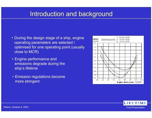
Introduction and background<br />
• During the design stage <strong>of</strong> a ship, engine<br />
operating parameters are selected /<br />
optimised for one operating point (usually<br />
close to MCR)<br />
• Engine performance and<br />
emissions degrade during the<br />
ship’s lifetime<br />
• Emission regulations become<br />
more stringent<br />
Athens, October 8, 2003<br />
<strong>Final</strong> <strong>Presentation</strong>
Introduction and background<br />
Y<br />
X<br />
CONTROL<br />
UNIT<br />
Athens, October 8, 2003<br />
<strong>Final</strong> <strong>Presentation</strong>
LOW IN FUEL AND EMISSIONS TWO-STROKE<br />
INTELLIGENT MARINE ENGINE<br />
GROWTH Project G3RD-CT-2000-00245 - STARTING DATE: 1.4.2000 - DURATION: 39 months<br />
• DANAOS Shipping Co. (EL)<br />
• National Technical University <strong>of</strong> Athens / LME (EL)<br />
• MAN B&W Diesel A/S (DK)<br />
• ABB Service A/S (DK)<br />
• Germanischer Lloyd AG (D)<br />
• Hapag-Lloyd Container Linie AG (D)<br />
• CIMAC - National Members Association Greece (EL)<br />
Athens, October 8, 2003<br />
<strong>Final</strong> <strong>Presentation</strong>
Objectives and Methodology<br />
<strong>LIFETIME</strong> OBJECTIVES:<br />
To establish correlations between performance,<br />
emissions, and engine operating parameters, applicable to<br />
a wide variety <strong>of</strong> direct drive marine engines.<br />
To develop control systems including the correlations<br />
above, able to optimise engine performance, based on<br />
standard measurable operating and external parameters, with<br />
emissions level as an optimisation constraint.<br />
Athens, October 8, 2003<br />
<strong>Final</strong> <strong>Presentation</strong>
Objectives and Methodology<br />
<strong>LIFETIME</strong> METHODOLOGY:<br />
(I) To perform a series <strong>of</strong> full scale shipboard tests and<br />
testbed experiments <strong>of</strong> powerplant performance and<br />
emissions for large two stroke marine engines, to compound<br />
the partner’s cumulated experience and information<br />
repository<br />
Athens, October 8, 2003<br />
<strong>Final</strong> <strong>Presentation</strong>
Objectives and Methodology<br />
<strong>LIFETIME</strong> METHODOLOGY:<br />
(II) To conduct a series <strong>of</strong> detailed simulations <strong>of</strong> ship powerplant<br />
operation using comprehensive advanced mathematical<br />
models, calibrated using the results <strong>of</strong> (I), so as to arrive at<br />
OBJ.1:<br />
Correlations linking performance, emissions and the<br />
engine parameters.<br />
Athens, October 8, 2003<br />
<strong>Final</strong> <strong>Presentation</strong>
Objectives and Methodology<br />
<strong>LIFETIME</strong> METHODOLOGY:<br />
(III) To use simulation models, in combination with engine control<br />
systems design procedures and electronic system test bed<br />
trials, so as to arrive at OBJ.2 :<br />
Engine add-on systems including the optimisation<br />
correlations <strong>of</strong> OBJ.1.<br />
Athens, October 8, 2003<br />
<strong>Final</strong> <strong>Presentation</strong>
Objectives and Methodology<br />
<strong>LIFETIME</strong> METHODOLOGY:<br />
(IV) To install prototype systems respectively on:<br />
- A conventional direct-drive slow-speed engine <strong>of</strong> a<br />
Danaos containership<br />
- A state-<strong>of</strong>-the-art ultra-large-bore engine <strong>of</strong> a newly built<br />
Hapag-Lloyd containership<br />
- The “Intelligent" engine <strong>of</strong> the MAN B&W research testbed<br />
Athens, October 8, 2003<br />
<strong>Final</strong> <strong>Presentation</strong>
Objectives and Methodology<br />
<strong>LIFETIME</strong> PROTOTYPE CONTROL SYSTEM<br />
2-stroke <strong>Marine</strong> Diesel Engine<br />
- Cylinder pressures<br />
and temperatures<br />
- Receivers pressures<br />
and temperatures<br />
- Crankshaft speed,<br />
torque and position<br />
- T/C speed<br />
- Fuel index<br />
- Lub oil pressure<br />
and temperature<br />
Control System<br />
- Ambient conditions<br />
- Fuel quality<br />
Set <strong>of</strong> Correlations between<br />
performance, emissions and<br />
engine operating parameters<br />
- Injection timing<br />
- Exhaust valve closing<br />
- Injection pulse<br />
- Lub oil dosage<br />
- T/C system control<br />
- Air cooler contol<br />
- Starting air system control<br />
- Cylinders and turbochargers<br />
cut out at part loads<br />
Control schemes algorithm<br />
Emissions<br />
Estimation<br />
- Optimization criterion<br />
- Ordered speed<br />
Athens, October 8, 2003<br />
<strong>Final</strong> <strong>Presentation</strong>
Work Overview<br />
On-board<br />
Experiments<br />
Simulations<br />
Correlations<br />
<strong>LIFETIME</strong> PROTOTYPE<br />
SYSTEMS<br />
Observer<br />
Testbed<br />
Experiments<br />
Control<br />
Schedules<br />
Engine<br />
Control<br />
Unit<br />
Full Scale<br />
Tests<br />
Analysis <strong>of</strong><br />
results<br />
Athens, October 8, 2003<br />
<strong>Final</strong> <strong>Presentation</strong>
Vessels for shipboard measurement campaigns<br />
Hapag-Lloyd’s containership “Antwerpen Express”<br />
Hapag-Lloyd’s containership “Shanghai Express”<br />
Odfjell’s chemical carrier “Bow Cecil”<br />
Athens, October 8, 2003<br />
<strong>Final</strong> <strong>Presentation</strong>
Research Centre and Intelligent Engine Testbed<br />
Exterior view <strong>of</strong> the MAN B&W facility<br />
Athens, October 8, 2003<br />
<strong>Final</strong> <strong>Presentation</strong>
Research Centre and Intelligent Engine Testbed<br />
View <strong>of</strong> the engine testbed with the 4T50MX Research Engine<br />
Athens, October 8, 2003<br />
<strong>Final</strong> <strong>Presentation</strong>
The two possible configurations <strong>of</strong> the Intelligent Engine<br />
Installation <strong>of</strong> the IE<br />
Fuel Injection and Exhaust Valve<br />
control systems<br />
in parallel to<br />
the conventional camshaft<br />
on the 6L60MC engine<br />
Athens, October 8, 2003<br />
<strong>Final</strong> <strong>Presentation</strong>
Turbocharger test centre<br />
Exterior view <strong>of</strong> the ABB facility<br />
Athens, October 8, 2003<br />
<strong>Final</strong> <strong>Presentation</strong>
Turbocharger test centre<br />
ABB Turbocharger on the test rig<br />
Athens, October 8, 2003<br />
<strong>Final</strong> <strong>Presentation</strong>
Intelligent Engine<br />
Performance<br />
& Emissions<br />
Investigations<br />
MAN B&W Testbed<br />
“Bow Cecil” engine room<br />
Athens, October 8, 2003<br />
<strong>Final</strong> <strong>Presentation</strong>
Turbocharger measurement points setup<br />
Turbine blades<br />
(condition as supplied for tests)<br />
Turbocharger<br />
Performance<br />
Investigations<br />
at ABB Testbed<br />
Athens, October 8, 2003<br />
<strong>Final</strong> <strong>Presentation</strong>
Turbine nozzle ring contamination<br />
Nozzle ring No1<br />
(condition as supplied for tests)<br />
Nozzle ring No2<br />
(condition as supplied for tests)<br />
Athens, October 8, 2003<br />
<strong>Final</strong> <strong>Presentation</strong>
Compressor impeller preparation<br />
Compressor wheel<br />
coated with glass fibres<br />
Athens, October 8, 2003<br />
<strong>Final</strong> <strong>Presentation</strong>
Compressor<br />
Athens, October 8, 2003<br />
<strong>Final</strong> <strong>Presentation</strong>
Partners onboard “Shanghai Express” for measurements<br />
Athens, October 8, 2003<br />
<strong>Final</strong> <strong>Presentation</strong>
“Shanghai Express” Propulsion Plant: 9K90MC engine<br />
Athens, October 8, 2003<br />
<strong>Final</strong> <strong>Presentation</strong>
Measurement <strong>of</strong> brake power, MS “Shanghai Express”<br />
Athens, October 8, 2003<br />
<strong>Final</strong> <strong>Presentation</strong>
Comparison <strong>of</strong> independent power measurement<br />
for main engine MS “Shanghai Express”<br />
Athens, October 8, 2003<br />
<strong>Final</strong> <strong>Presentation</strong>
MS “Shanghai Express” sampling points for gaseous emissions (1), particulate matter (2),<br />
opacity (3) and filter smoke number (4)<br />
Athens, October 8, 2003<br />
<strong>Final</strong> <strong>Presentation</strong>
“Shanghai Express”<br />
Exhaust gas<br />
measurements<br />
Sampling probe for gaseous emission<br />
Sampling probe for particulate emission<br />
Sampling points and analysers for<br />
measurement <strong>of</strong> opacity<br />
and filter smoke number<br />
Sampling point for gaseous<br />
and particulate emission<br />
Athens, October 8, 2003<br />
<strong>Final</strong> <strong>Presentation</strong>
“Shanghai-Express” - ABB DAQ (SeMCa) connected to the 3rd turbocharger<br />
Athens, October 8, 2003<br />
<strong>Final</strong> <strong>Presentation</strong>
“Antwerpen Express” Propulsion Plant: 7K98MC engine<br />
Athens, October 8, 2003<br />
<strong>Final</strong> <strong>Presentation</strong>
“Antwerpen Express”<br />
Air management<br />
system<br />
measurements<br />
Turbine outlet measurements<br />
Temperature and pressure<br />
Compressor outlet measurements<br />
Temperature and pressure<br />
Turbocharger speed sensor<br />
Air-filter with thermocouples<br />
Athens, October 8, 2003<br />
<strong>Final</strong> <strong>Presentation</strong>
Measuring data acquisition system ZXTFLEX/ABB<br />
onboard “Antwerpen Express”<br />
Athens, October 8, 2003<br />
<strong>Final</strong> <strong>Presentation</strong>
Analysers for exhaust gas measurement, MS “Antwerpen Express”<br />
Athens, October 8, 2003<br />
<strong>Final</strong> <strong>Presentation</strong>
Analysis <strong>of</strong> ageing effect<br />
The ageing process<br />
Athens, October 8, 2003<br />
<strong>Final</strong> <strong>Presentation</strong>
Analysis <strong>of</strong> ageing effect - Methodology<br />
Collection <strong>of</strong> performance data and component running hours for 4 ships<br />
(DANAOS, HL, GCA members) out <strong>of</strong> 12 candidate<br />
Data pre-processing and selection <strong>of</strong> key operational parameters to be<br />
investigated<br />
Statistical analysis <strong>of</strong> ageing ratios - regression models<br />
Results assessment - conclusions<br />
Athens, October 8, 2003<br />
<strong>Final</strong> <strong>Presentation</strong>
Analysis <strong>of</strong> ageing effect - Data Summary<br />
Athens, October 8, 2003<br />
<strong>Final</strong> <strong>Presentation</strong>
Analysis <strong>of</strong> ageing effect - Typical results<br />
Ship: Maersk Livorno<br />
(DANAOS)<br />
30%<br />
ε∆Pcyl_cmp<br />
25%<br />
20%<br />
The ageing ratio is defined as a deviation ratio <strong>of</strong> the operating parameter<br />
15%<br />
value, in a specific engine load condition, to the corresponding value <strong>of</strong> the<br />
10%<br />
5% sea trial performance curves.<br />
0%<br />
35000 40000 45000 50000 55000 60000 65000 70000 75000 80000 85000<br />
M/E Hours Period1 Period2 Period3 EST EST21 Linear (Period1) Linear (Period2) Linear (Period3)<br />
Compression pressure ageing ratio ε and corresponding ageing models<br />
30%<br />
25%<br />
20%<br />
15%<br />
10%<br />
5%<br />
ε∆Texh_bTC<br />
20000<br />
18000<br />
16000<br />
14000<br />
12000<br />
10000<br />
8000<br />
6000<br />
4000<br />
2000<br />
TC Hours<br />
0%<br />
0<br />
35000 40000 45000 50000 55000 60000 65000 70000 75000 80000<br />
M/E Hours<br />
TC Hours Period1 Period2 Peiod3 Predict Linear (Period1) Linear (Period2) Linear (Peiod3)<br />
Exhaust gas temperature before T/C ageing ratio ε and corresponding ageing models<br />
Athens, October 8, 2003<br />
<strong>Final</strong> <strong>Presentation</strong>
Analysis <strong>of</strong> ageing effect - Conclusions<br />
♦ Performance degradation significant after 15000 hours<br />
♦ Newly built ships no ageing phenomena for 2 years (min)<br />
♦ Established ageing effects (after 15000 – 20000 hrs)<br />
- Exhaust Temperature before T/C<br />
- Cylinder compression pressure<br />
- Turbocharger speed<br />
- Scavenging air pressure.<br />
♦ 5% increase in SFOC AGEING<br />
Athens, October 8, 2003<br />
<strong>Final</strong> <strong>Presentation</strong>
Multi-zone Combustion Model<br />
EQUIVALENCE RATIO MAP, 10 deg ATDC<br />
TEMPERATURE MAP, 10 deg ATDC<br />
71<br />
61<br />
41<br />
21<br />
1<br />
2<br />
3<br />
1.5<br />
1.4<br />
1.3<br />
1.2<br />
1.1<br />
1.0<br />
0.9<br />
0.8<br />
0.7<br />
0.6<br />
0.5<br />
0.4<br />
2500<br />
2400<br />
2300<br />
2200<br />
2100<br />
2000<br />
1900<br />
1800<br />
1700<br />
1600<br />
1500<br />
FUEL JET DEVELOPMENT vs TIME<br />
GREY : 0 deg ATDC<br />
PURPLE : 5 deg ATDC<br />
BLUE : 10 deg ATDC<br />
RED : 20 deg ATDC<br />
FUEL BURNT PERCENTAGE MAP, 10 deg ATDC<br />
NOx MAP, 10 deg ATDC<br />
100<br />
90<br />
80<br />
70<br />
60<br />
50<br />
40<br />
30<br />
20<br />
10<br />
0<br />
3000<br />
2750<br />
2500<br />
2250<br />
2000<br />
1750<br />
1500<br />
1250<br />
1000<br />
750<br />
500<br />
250<br />
0<br />
Fuel spray development<br />
with time<br />
Maps in fuel spray at one time instant:<br />
Equivalence ratio<br />
Temperature<br />
% fuel mass burnt<br />
NOx<br />
Athens, October 8, 2003<br />
<strong>Final</strong> <strong>Presentation</strong>
Multi-zone Combustion Model<br />
NOx MAP, 0 deg ATDC<br />
3000<br />
2750<br />
2500<br />
2250<br />
2000<br />
1750<br />
1500<br />
1250<br />
1000<br />
750<br />
500<br />
250<br />
100<br />
50<br />
10<br />
0<br />
NOx MAP (ppm), 5 deg ATDC<br />
3000<br />
2750<br />
2500<br />
2250<br />
2000<br />
1750<br />
1500<br />
1250<br />
1000<br />
750<br />
500<br />
200<br />
100<br />
50<br />
0<br />
NOx MAP, 10 deg ATDC<br />
NOx MAP, 20 deg ATDC<br />
3000<br />
2750<br />
2500<br />
2250<br />
2000<br />
1750<br />
1500<br />
1250<br />
1000<br />
750<br />
500<br />
250<br />
0<br />
5000<br />
4000<br />
3000<br />
2750<br />
2500<br />
2250<br />
2000<br />
1750<br />
1500<br />
1250<br />
1000<br />
750<br />
500<br />
250<br />
0<br />
NOx maps in fuel spray at 4 time instants<br />
Athens, October 8, 2003<br />
<strong>Final</strong> <strong>Presentation</strong>
Engine Performance Modelling<br />
“Shanghai Express”<br />
Measured engine<br />
performance<br />
data (7 hours)<br />
Athens, October 8, 2003<br />
<strong>Final</strong> <strong>Presentation</strong>
Engine Performance Modelling<br />
Comparison between measured data and simulation results<br />
after determining the engine governor constants<br />
Athens, October 8, 2003<br />
<strong>Final</strong> <strong>Presentation</strong>
T/C Fouling Modelling<br />
Endurance test<br />
with high ash fuel<br />
on a large 4-S engine<br />
Athens, October 8, 2003<br />
<strong>Final</strong> <strong>Presentation</strong>
Simulations - 7K98MC engine<br />
PARAMETRIC RUNS<br />
Measured and predicted engine<br />
performance and emissions parameters<br />
for various values <strong>of</strong> VIT change<br />
Athens, October 8, 2003<br />
<strong>Final</strong> <strong>Presentation</strong>
Simulations - 7K98MC engine<br />
NOx model Validation<br />
Predicted NOx using MOTHER and comparison with engine shop trials data<br />
Athens, October 8, 2003<br />
<strong>Final</strong> <strong>Presentation</strong>
Simulations - 7K98MC engine<br />
Creation <strong>of</strong> parameter maps (to be used for control)<br />
NOx (gr/kWh)<br />
23<br />
22<br />
21<br />
20<br />
19<br />
18<br />
17<br />
16<br />
15<br />
14<br />
13<br />
12<br />
11<br />
10<br />
Engine Load @ 75% <strong>of</strong> MCR<br />
VIT Change (deg)<br />
184<br />
183<br />
182<br />
181<br />
180<br />
179<br />
178<br />
177<br />
176<br />
175<br />
174<br />
173<br />
BSFC (gr/kWh)<br />
9<br />
-5 -4 -3 -2 -1 0 1 2 3 4 5<br />
Fuel Index Change (%)<br />
172<br />
-5 -4 -3 -2 -1 0 1 2 3 4 5<br />
Fuel Index Change (%)<br />
Typical NOx and BSFC maps for 75% load<br />
Athens, October 8, 2003<br />
<strong>Final</strong> <strong>Presentation</strong>
Simulations <strong>of</strong> Ageing and Wear<br />
Empirical models <strong>of</strong> component wear<br />
Piston ring wear<br />
Cylinder liner wear<br />
Athens, October 8, 2003<br />
<strong>Final</strong> <strong>Presentation</strong>
Possible Types <strong>of</strong> Correlation<br />
• Ship-specific look-up table<br />
* Simple but less accurate<br />
* Results based on a few experimental measurements<br />
* Valid only in range close to the measured values<br />
• Process model<br />
* Physical model including in-cylinder processes for NOx formation<br />
* Able to account for out-<strong>of</strong>-range inputs<br />
* Ageing effect can be incorporated<br />
* Higher execution time<br />
Athens, October 8, 2003<br />
<strong>Final</strong> <strong>Presentation</strong>
<strong>LIFETIME</strong> Control System<br />
INTELLIGENT Engine<br />
Control System<br />
Set <strong>of</strong> Correlations between<br />
performance, emissions and<br />
engine operating parameters<br />
Control schemes algorithm<br />
Ship-specific correlation to be included in “Control” system<br />
Athens, October 8, 2003<br />
<strong>Final</strong> <strong>Presentation</strong>
<strong>LIFETIME</strong> Control System<br />
Mathematical functional correlation (MAN B&W):<br />
where K 1 , K 2 , α engine-specific constants<br />
Oxygen concentration & Maximum temperature from:<br />
* A/F ratio (stoichiometric)<br />
* Scavenging pressure<br />
* Scavenging temperature<br />
* other measured operational parameters<br />
Athens, October 8, 2003<br />
<strong>Final</strong> <strong>Presentation</strong>
<strong>LIFETIME</strong> observer system (NOx-Box)<br />
2-S <strong>Marine</strong> Diesel Engine<br />
- Receivers pressures<br />
and temperatures<br />
- Crankshaft speed,<br />
and torque<br />
- T/C speed<br />
- Fuel index<br />
- VIT<br />
Observer System<br />
Process model<br />
was included<br />
in “observer”<br />
(NTUA)<br />
MOTHER<br />
Mathematical Model<br />
NOx<br />
Estimation<br />
Athens, October 8, 2003<br />
<strong>Final</strong> <strong>Presentation</strong>
<strong>LIFETIME</strong> observer system (NOx-Box)<br />
• Process model (MoTher code) embedded in PC platform (NOx-BOX)<br />
• Several engine operating parameters required for input and validation purposes<br />
• PC connected to onboard Data Acquisition (DAQ) System<br />
NOx MAP, 10 deg ATDC<br />
3000<br />
2750<br />
2500<br />
2250<br />
2000<br />
1750<br />
1500<br />
1250<br />
1000<br />
750<br />
500<br />
250<br />
0<br />
SCAVENGING<br />
RECEIVER<br />
P,T<br />
INLET<br />
VALVES<br />
CYLINDERS<br />
RPM<br />
LOAD<br />
FUEL<br />
RACK<br />
EXHAUST<br />
VALVES<br />
VIT<br />
T e<br />
EXHAUST<br />
RECEIVER<br />
P,T<br />
TURBINE<br />
RPM<br />
PLENUM AFTER<br />
TURBINE<br />
P<br />
Embedded<br />
MoTher<br />
DAQ<br />
Monitoring<br />
system<br />
NOx-Box<br />
Communication<br />
Serial link<br />
Athens, October 8, 2003<br />
<strong>Final</strong> <strong>Presentation</strong>
<strong>LIFETIME</strong> observer system (NOx-Box)<br />
Calibration <strong>of</strong> estimated NOx value<br />
• Initial calibration using on-board measurements and simulation runs<br />
• Validation error (Predicted-Measured)<br />
• Error exceeds limit re-calibration <strong>of</strong> MoTher code constants<br />
IMPLEMENTATION<br />
• NOx-BOX onboard “Antwerpen Express” (HL) using automatic data input<br />
• NOx-BOX onboard “APL Scotland” (DANAOS) using manually inserted parameter<br />
values<br />
Athens, October 8, 2003<br />
<strong>Final</strong> <strong>Presentation</strong>
<strong>LIFETIME</strong> observer system (NOx-Box)<br />
DANAOS Containership“APL Scotland”<br />
Hapag-Lloyd’s containership<br />
“Antwerpen Express”<br />
Athens, October 8, 2003<br />
<strong>Final</strong> <strong>Presentation</strong>
Determination <strong>of</strong> the operating parameters to be controlled<br />
Determination based on:<br />
• Simulation results <strong>of</strong> the powerplant performance performed in WP5<br />
(Powerplant simulation)<br />
• Engine-specific correlation between operating prameters and emissions<br />
obtained in WP6<br />
• Available control options for the conventional and intelligent engines.<br />
Basic selected controlled parameters<br />
• Injection timing<br />
• Choice <strong>of</strong> injection pr<strong>of</strong>ile<br />
• Exhaust valve open timing<br />
• Exhaust valve close timing<br />
• Hydraulic supply pressure (injection pressure)<br />
Athens, October 8, 2003<br />
<strong>Final</strong> <strong>Presentation</strong>
Validation <strong>of</strong> control schemes<br />
Development <strong>of</strong> engine running modes<br />
• Low Emission mode<br />
• Economy Mode<br />
4.0<br />
170<br />
160<br />
150<br />
Fuel Injection & Exhaust Valve Timing<br />
Cylinder Pressure<br />
Fuel Oil Consumption<br />
Low Emission mode<br />
Low Emission mode<br />
Economy mode<br />
Economy mode<br />
Exhaust valve close<br />
Pmax<br />
Pcomp<br />
Low Emission mode<br />
Economy mode<br />
2.0<br />
140<br />
[g /kW h ]<br />
0.0<br />
-2.0<br />
Timing<br />
[bar abs.]<br />
130<br />
120<br />
110<br />
100<br />
Exhaust valve open<br />
-4.0<br />
90<br />
-6.0<br />
80<br />
Injection Timing<br />
70<br />
50 60 70 80 90 100 110<br />
50 60 70 80 90 100 110<br />
50 60 70 Engine 80 Load [%] 90 100 110<br />
Engine Load [%]<br />
Engine Load [%]<br />
Athens, October 8, 2003<br />
<strong>Final</strong> <strong>Presentation</strong>
Testbed implementation <strong>of</strong> the control schemes<br />
Validation <strong>of</strong> the control schemes in the MAN B&W testbed<br />
in Copenhagen in order to:<br />
• To expand the knowledge <strong>of</strong> the engine combustion cycle with regard<br />
to exhaust emissions and efficiency<br />
• To determine the influence <strong>of</strong> variation in-cylinder compression<br />
pressure and maximum combustion pressure on the engine operational<br />
behaviour<br />
• To make an initial evaluation <strong>of</strong> the control schemes proposed for the<br />
intelligent engine and to expand the knowledge with regard to<br />
adjustments on the conventional (mechanically actuated) engine<br />
• A test series <strong>of</strong> 42 tests (about 1000 running hours) was carried out with a<br />
parameter variation <strong>of</strong> compression pressure and maximum firing pressure<br />
Athens, October 8, 2003<br />
<strong>Final</strong> <strong>Presentation</strong>
Analysis<br />
Observations:<br />
• For a fixed Pmax, decreasing Pcomp (or increasing Pmax minus Pcomp<br />
pressure) results in decreasing NOx. The effect is small at high loads, but<br />
stronger at lower loads<br />
• The HC emission at high loads (75% and 100%) is not affected by either Pmax<br />
or Pcomp variations<br />
• CO emissions decrease with increasing Pcomp, i.e. decreasing with higher<br />
air/fuel ratio caused by larger air amount trapped in the cylinder at the higher<br />
compression pressure<br />
• The effect <strong>of</strong> Pmax and Pcomp on PM (Particulate matter) emission follows the<br />
same trend as that <strong>of</strong> HC emission<br />
• Use <strong>of</strong> the compression pressure influence on NOx emissions, in the<br />
MAN B&W NOx function.<br />
Athens, October 8, 2003<br />
<strong>Final</strong> <strong>Presentation</strong>
Prototype Control Systems<br />
Design and implementation <strong>of</strong> the prototype control systems<br />
• MAN B&W Prototype for the Intelligent Engine<br />
• On-line NOx-BOX observer system for the ultra-large bore engine<br />
• Off-line NOx-BOX observer system for the conventional engine<br />
Managerial decision<br />
• “Antwerpen Express” <strong>of</strong> HL was replaced by “Tokyo Express” <strong>of</strong> HL for the<br />
measurement campaign.<br />
Initial calibration <strong>of</strong> the prototype control systems<br />
Athens, October 8, 2003<br />
<strong>Final</strong> <strong>Presentation</strong>
Ultra-Large Bore Engine<br />
On-line NOx-BOX Observer System - General<br />
• A portable computer connected to the ship’s engine monitoring system able to<br />
calculate continuously the level <strong>of</strong> NOx emission<br />
• Includes the MOTHER simulation code to calculate the engine NOx level<br />
using the values <strong>of</strong> several measured engine operating parameters<br />
• Input data for the NOx-BOX calculations are provided on-line by the<br />
monitoring system <strong>of</strong> the ship<br />
SCAVENGING<br />
RECEIVER<br />
P,T<br />
INLET<br />
VALVES<br />
CYLINDERS<br />
RPM<br />
FUEL<br />
RACK<br />
EXHAUST<br />
VALVES<br />
VIT<br />
EXHAUST<br />
RECEIVER<br />
P,T<br />
TURBINE<br />
RPM<br />
PLENUM AFTER<br />
TURBINE<br />
P<br />
LOAD<br />
T e<br />
Athens, October 8, 2003<br />
<strong>Final</strong> <strong>Presentation</strong>
Brake Power<br />
per cylinder (kW)<br />
Ultra-Large Bore Engine<br />
On-line NOx-BOX Observer System - Development<br />
160<br />
• Development <strong>of</strong> the User Interface<br />
Pmax (bar)<br />
BSFOC (gr/kWh)<br />
Rel. A/F Ratio (-)<br />
6000<br />
5000<br />
4000<br />
3000<br />
2000<br />
1000<br />
BMEP (bar)<br />
140<br />
120<br />
100<br />
Predicted<br />
80<br />
Reference data<br />
60<br />
185<br />
180<br />
175<br />
170<br />
165<br />
160<br />
2.8<br />
2.6<br />
2.4<br />
2.2<br />
2<br />
1.8<br />
1.6<br />
20<br />
18<br />
16<br />
14<br />
12<br />
10<br />
8<br />
6<br />
20 30 40 50 60 70 80 90 100 110<br />
Load (%)<br />
• Development <strong>of</strong> the communication protocol between the NOx-BOX and the<br />
25<br />
ship’s monitoring system – Testing with STN ATLAS emulator<br />
• Initial calibration using the engine shop trials<br />
NOx (gr/kWh)<br />
30<br />
20<br />
15<br />
10<br />
5<br />
30 40 50 60 70 80 90 100 110<br />
Load (%)<br />
MOTHER results<br />
Engine Shop Trials<br />
Athens, October 8, 2003<br />
<strong>Final</strong> <strong>Presentation</strong>
Engine Running Mode s<strong>of</strong>tware has been developed and integrated<br />
in the ME Engine Control System (ECS). It includes:<br />
• The generic engine running mode<br />
• The engine running mode controller<br />
Intelligent Engine<br />
• The injection and exhaust valve close timing maps<br />
Fuel Injection & Exhaust Valve Timing<br />
• The user interface on Main Operating Panel <strong>of</strong> the ECS<br />
Low Emission mode<br />
Economy mode<br />
Exhaust valve close<br />
Timing<br />
Exhaust valve open<br />
Injection Timing<br />
Athens, October 8, 2003<br />
50 60 70 80 90 100 110<br />
Engine Load [%]<br />
<strong>Final</strong> <strong>Presentation</strong>
Conventional Engine<br />
Off-line NOx-BOX Observer System - General<br />
• A computer able to calculate the level <strong>of</strong> NOx emission manual data input <strong>of</strong><br />
measured engine operating parameters<br />
VESSEL: ENGINE: MAN B&W 12K90 MC<br />
• Includes the MOTHER simulation<br />
Engine Operation<br />
code<br />
Data<br />
to calculate the engine NOx level<br />
(Fill the values <strong>of</strong> the shipboard measurement<br />
instruments;<br />
using measured engine operating parameters<br />
Date: Date: Date:<br />
use the units indicated in brackets) Time Time Time Time Time Time Time Time Time<br />
Scav. Air Pressure (receiver) [bar]<br />
• Input data for the NOx-BOX calculations are provided <strong>of</strong>f-line by the ship’s<br />
Scav. air temp. after cooler [deg C]<br />
operator<br />
Exhaust Receiver Pressure [bar]<br />
Turbine Inlet Temperature [deg C]<br />
Barometric Pressure (engine room) [mbar]<br />
Shaft Torque [kNm]<br />
Engine Speed [rpm]<br />
Engine Power (MID) [BHP]<br />
Engine Power (SEMS) [BHP]<br />
Fuel Pump Index (average) [-]<br />
Pmax adjustment index (V.I.T.) [-]<br />
Turbocharger RPM [rpm]<br />
Athens, October 8, 2003<br />
Pmax [bar] (if available)<br />
<strong>Final</strong> <strong>Presentation</strong>
Conventional Engine<br />
Off-line NOx BOX Observer System - Development<br />
• Development <strong>of</strong> the User Interface<br />
• Initial calibration using the engine shop trials<br />
Athens, October 8, 2003<br />
<strong>Final</strong> <strong>Presentation</strong>
Prototype Control Systems<br />
Initial installation <strong>of</strong> the prototype control systems<br />
• MAN B&W Prototype for the Intelligent Engine (MAN B&W Testbed,<br />
Copenhagen)<br />
• On-line NOx-BOX observer system for the ultra-large bore engine (Tokyo<br />
Express)<br />
• Off-line NOx-BOX observer system for the conventional engine (APL<br />
Scotland)<br />
Athens, October 8, 2003<br />
<strong>Final</strong> <strong>Presentation</strong>
Ultra-Large Bore Engine<br />
On-line NOx-BOX Observer System<br />
• Installed onboard “Tokyo Express” <strong>of</strong> HL at the port <strong>of</strong> Bremerhaven<br />
• After the initial functionality tests, full system tests were performed during normal<br />
ship operation, while sailing towards Le Havre (France) with an intermediate stop at<br />
Rotterdam<br />
• After the completion <strong>of</strong> the trip, the prototype NOx-BOX was removed and taken<br />
back to NTUA for analysis <strong>of</strong> results and re-calibration<br />
Athens, October 8, 2003<br />
<strong>Final</strong> <strong>Presentation</strong>
Intelligent Engine<br />
Engine Running Mode s<strong>of</strong>tware installation<br />
• New Engine Control System (ECS) hardware & cabling<br />
• New mechanical/hydraulic components for controlling exhaust valve, injection<br />
valve and start air valves<br />
• The injection and exhaust valve close timing maps<br />
• Test setup for providing stimuli from all control stations (Bridge, ECR and<br />
Local)<br />
Athens, October 8, 2003<br />
<strong>Final</strong> <strong>Presentation</strong>
Conventional Engine<br />
Off-line NOx-BOX Observer System - Installation<br />
• A CD with the installation program <strong>of</strong> the OFF-LINE NOx-BOX prototype was<br />
sent to “APL Scotland” containership <strong>of</strong> DANAOS for installation<br />
• The program was installed on a ship's computer and worked with manually<br />
entered data<br />
Athens, October 8, 2003<br />
<strong>Final</strong> <strong>Presentation</strong>
Prototype Control Systems<br />
Recalibration <strong>of</strong> the prototype control systems<br />
• Recalibration <strong>of</strong> the on-line NOx-BOX system sea-trials onboard “Tokyo<br />
Express”<br />
• Latest corrections and final calibration / fine-tuning <strong>of</strong> the intelligent engine<br />
control system (ECS) in the MAN B&W testbed in Copenhagen.<br />
• No recalibration needed for the Off-line version <strong>of</strong> NOx-BOX onboard APL<br />
Scotland.<br />
Athens, October 8, 2003<br />
<strong>Final</strong> <strong>Presentation</strong>
Ultra-Large 140 Bore 5000 Engine<br />
120<br />
On-line NOx-BOX Observer System<br />
Pmax (bar)<br />
100<br />
• The analysis <strong>of</strong> “Tokyo Express” sea trials, led to the necessity <strong>of</strong> NOx-BOX<br />
80<br />
measured<br />
2000<br />
predicted<br />
prototype recalibration.<br />
60<br />
kW/CYL<br />
4000<br />
3000<br />
1000<br />
20 40 60 80 100<br />
Load %<br />
20 40 60 80 100<br />
Load %<br />
40000<br />
• The severe fluctuations 24 <strong>of</strong> predicted NOx emissions and brake power at part<br />
loads were attributed 20to:<br />
30000<br />
NOx [gr/kWh]<br />
16<br />
• the deviation <strong>of</strong> “Tokyo Express” propeller curve from “Antwerpen<br />
12<br />
Express” propeller curve, used in initial calibration.<br />
10000<br />
8<br />
• the narrow initial calibration range <strong>of</strong> prototype<br />
20 40 60 80 100<br />
Load %<br />
50 60 70 80 90 100<br />
Engine rpm<br />
• Recalibration was performed with use <strong>of</strong> the results <strong>of</strong> the “Tokyo Express”<br />
sea trials.<br />
Pb [kW]<br />
20000<br />
Athens, October 8, 2003<br />
<strong>Final</strong> <strong>Presentation</strong>
Conventional Engine<br />
Off-line NOx_BOX Observer System<br />
• The initial calibration <strong>of</strong> the OFF-LINE NOx-BOX prototype was successful<br />
and good agreement between the recorded and calculated engine<br />
performance parameters has been obtained during the onboard tests<br />
28<br />
K90 Simulation Results<br />
160<br />
26<br />
140<br />
• No re-calibration <strong>of</strong> the OFF-LINE<br />
Measured<br />
NOx-BOX prototype was necessary<br />
Predicted<br />
24<br />
120<br />
22<br />
100<br />
20<br />
80<br />
18<br />
60<br />
N Ox (g r/KWh)<br />
55 60 65 70 75 80 85 90 95<br />
rpm<br />
Pow e r (KW/cyl)<br />
5000<br />
4000<br />
3000<br />
2000<br />
1000<br />
0<br />
M a xim u m Pre ssu re (b a r)<br />
55 60 65 70 75 80 85 90 95<br />
rpm<br />
55 60 65 70 75 80 85 90 95<br />
rpm<br />
Athens, October 8, 2003<br />
<strong>Final</strong> <strong>Presentation</strong>
Ultra-Large Bore Engine<br />
On-line NOx-BOX Observer System<br />
• The ON-LINE NOx-BOX prototype was re-installed onboard “Tokyo Express” at<br />
the port <strong>of</strong> Bremerhaven, for the sea trial campaign to the port <strong>of</strong> Le Havre,<br />
France<br />
• The prototype used the same protocols and connection equipment as in the<br />
previous trials (Sep 2002), since no communication problem was observed<br />
• Initial functionality tests and full system tests were performed. During the trip the<br />
data acquired were logged in order to be analysed in WP11.<br />
Athens, October 8, 2003<br />
<strong>Final</strong> <strong>Presentation</strong>
Engine Running Mode s<strong>of</strong>tware<br />
Intelligent Engine<br />
• The installation <strong>of</strong> test wall for in-<strong>of</strong>fice ‘hardware in the loop’ test <strong>of</strong> the<br />
complete ECS was completed on the Intelligent engine T50ME-X<br />
• A series <strong>of</strong> functionality tests, preparing the system for the full-scale trials<br />
was also performed.<br />
• The following parameters have been calibrated in order to achieve the<br />
desired performance and emission values for the two running modes<br />
(optimisation <strong>of</strong> SFOC or NOx emissions):<br />
• Compression ratio as function <strong>of</strong> engine load<br />
• Maximum cylinder pressure as function <strong>of</strong> engine load<br />
• Exhaust valve open angle as function <strong>of</strong> engine load<br />
• Hydraulic supply pressure as function <strong>of</strong> engine load<br />
Athens, October 8, 2003<br />
<strong>Final</strong> <strong>Presentation</strong>
Work Overview<br />
On-board<br />
Experiments<br />
Simulations<br />
Correlations<br />
<strong>LIFETIME</strong> PROTOTYPE<br />
SYSTEMS<br />
Observer<br />
Testbed<br />
Experiments<br />
Control<br />
Schedules<br />
Engine<br />
Control<br />
Unit<br />
Full Scale<br />
Tests<br />
Analysis <strong>of</strong><br />
results<br />
Athens, October 8, 2003<br />
<strong>Final</strong> <strong>Presentation</strong>
Ultra-Large Bore Engine<br />
On-line NOx-BOX Observer System<br />
• Full scale measurements <strong>of</strong> the engine performance and emissions were<br />
performed onboard “Tokyo Express”<br />
• Measurements were conducted with the ship main engine operating on 23 -<br />
100% <strong>of</strong> its rated power.<br />
• Operational parameters <strong>of</strong> the engine were measured by three independent<br />
sources (GL, MAN B&W and HL).<br />
• The On-line NOx-BOX kept log <strong>of</strong> the data and NOx estimates, gathered<br />
during the full-scale trials.<br />
Athens, October 8, 2003<br />
<strong>Final</strong> <strong>Presentation</strong>
GL Measurements<br />
Ultra-Large Bore Engine<br />
• Exhaust gas and fuel samples have been analysed in the laboratory <strong>of</strong> GL<br />
prior to onboard measurements to find out the particulate matter composition<br />
and the influence <strong>of</strong> fuel quality on emissions.<br />
• Emissions measurements at required operating points specified by IMO for<br />
Test Cycle E3 have been conducted.<br />
Test Cycle E3<br />
power<br />
100 %<br />
75 %<br />
50 %<br />
25 %<br />
speed<br />
100 %<br />
91 %<br />
80 %<br />
63 %<br />
Athens, October 8, 2003<br />
<strong>Final</strong> <strong>Presentation</strong>
GL Measurements<br />
Ultra-Large Bore Engine<br />
• The specific emissions were calculated with Method 2 (Carbon Balance)<br />
according to IMO NOX Technical Code.<br />
• The engine operational parameters were recorded by the partners.<br />
Parameter<br />
Unit<br />
Operating point / Power<br />
power % <strong>of</strong> max. actual power<br />
-<br />
100%<br />
91%<br />
83%<br />
58%<br />
55%<br />
30%<br />
23%<br />
power % <strong>of</strong> rated power<br />
-<br />
84%<br />
76%<br />
69%<br />
49%<br />
46%<br />
25%<br />
19%<br />
speed % <strong>of</strong> rated speed<br />
-<br />
98%<br />
96%<br />
91%<br />
81%<br />
80%<br />
63%<br />
55%<br />
measured power<br />
kW<br />
33575<br />
30427<br />
27725<br />
19529<br />
18416<br />
10054<br />
7794<br />
measured NO x<br />
in exhaust gas<br />
g/kWh<br />
16.0<br />
17.7<br />
17.9<br />
16.9<br />
18.0<br />
18.5<br />
19.4<br />
measured NO x<br />
in exhaust gas<br />
kg/h<br />
537<br />
538<br />
497<br />
330<br />
331<br />
186<br />
151<br />
weighting factor<br />
-<br />
0.2<br />
-<br />
0.5<br />
-<br />
0.15<br />
0.15<br />
-<br />
Athens, October 8, 2003<br />
<strong>Final</strong> <strong>Presentation</strong>
MAN B&W Measurements<br />
Ultra-Large Bore Engine<br />
40000<br />
• MAN B&W conducted measurements <strong>of</strong> ship operational data (power and<br />
rotational speed<br />
35000<br />
measurements) onboard “Tokyo Express”<br />
• Results<br />
Power, kW<br />
30000<br />
25000<br />
20000<br />
• The engine speed measurements for all three independent measurements<br />
differed<br />
15000<br />
not more than 1% in relation to the speed measured by GL.<br />
10000<br />
• The power measurement by MAN B&W was in a range <strong>of</strong> +7% to +12% in<br />
relation to 5000the GL power measurement<br />
• The on board 0 measurement system <strong>of</strong> the ship showed a maximum<br />
0 10 20 30 40 50 60 70 80 90 100<br />
difference <strong>of</strong> 10% (up to 15% for low Speed, engine rpm load).<br />
Germanischer Lloyd (GL) HAPAG-Lloyd, ship's system HAPAG-Lloyd / MAN B&W Diesel A/S, indicator system<br />
Test Cycle E3: “Test cycle for Propeller-law-operated main and propeller-law-operated auxiliary engine application “<br />
Athens, October 8, 2003<br />
<strong>Final</strong> <strong>Presentation</strong>
Ultra-Large Bore Engine<br />
On-line NOx-BOX Operation<br />
• The On-line NOx-BOX kept log <strong>of</strong> the data and NOx estimates, gathered<br />
during the full-scale trials performed in the sea-passage Bremerhaven-Le<br />
Havre.<br />
• Engine operational data were collected along with the estimates generated by<br />
the NOx-BOX inference algorithm.<br />
• Comparison <strong>of</strong> measured NOx by GL and calculated NOx by ON-LINE NOx-<br />
BOX has been conducted.<br />
Athens, October 8, 2003<br />
<strong>Final</strong> <strong>Presentation</strong>
Ultra-Large Bore Engine<br />
On-line NOx-BOX measurements – Selection <strong>of</strong> Results<br />
35000<br />
40000<br />
25<br />
Power<br />
Power<br />
vs.<br />
vs.<br />
Time<br />
RPM<br />
Laptop PC<br />
overheating period<br />
Power, kW<br />
Power, kW<br />
30000<br />
35000<br />
25000 30000<br />
20000 25000<br />
15000 20000<br />
10000 15000<br />
5000<br />
10000<br />
5000<br />
0<br />
Athens, October 8, 2003<br />
0<br />
NOx emissions, gr/kWh<br />
20:01:12<br />
20:29:15<br />
20<br />
15<br />
10<br />
5<br />
0<br />
Weighted emissions (IMO, Test Cycle 3) Measured, GL<br />
GL: 17.5 gr/kWh<br />
Measured - Dec 27, 2002<br />
Predicted<br />
(Dec 27, 2002) NTUA: No prediction 17.67 gr/kWh<br />
Predicted, NTUA<br />
due to “out (Dec 28, 2002) Measured - Dec 28, 2002<br />
<strong>of</strong> range data” error<br />
Calibration curve<br />
Measured<br />
21:06:44<br />
21:36:42<br />
22:10:07<br />
22:41:05<br />
23:10:51<br />
23:43:32<br />
8:37:19<br />
8:54:31<br />
9:13:10<br />
9:32:38<br />
9:52:04<br />
50 55 60 65 70 75 80 85 90 95<br />
Time (hh,mm,ss)<br />
RPM<br />
10:10:47<br />
10:32:50<br />
Measured - GL<br />
0 5000 10000 15000 20000 25000 30000 35000 40000<br />
Power, kW<br />
10:52:48<br />
11:10:07<br />
11:30:18<br />
11:49:46<br />
12:07:42<br />
13:06:57<br />
13:38:33<br />
13:59:18<br />
14:16:53<br />
14:34:22<br />
14:53:17<br />
<strong>Final</strong> <strong>Presentation</strong>
Ultra-Large Bore Engine<br />
On-line NOx-BOX Observer System<br />
NOx<br />
Estimation<br />
Athens, October 8, 2003<br />
<strong>Final</strong> <strong>Presentation</strong>
Intelligent Engine - Results<br />
Intelligent Engine<br />
• The full-scale tests included variation <strong>of</strong> the controllable parameters for the<br />
two running modes under consideration (emission mode, performance mode)<br />
• A series <strong>of</strong> functionality tests, preparing the system for the full-scale trials was<br />
also performed.<br />
• The full-scale tests demonstrated the flexibility <strong>of</strong> the system, and the<br />
possibilities with regard to emission and fuel consumption adjustment.<br />
Athens, October 8, 2003<br />
<strong>Final</strong> <strong>Presentation</strong>
Conventional Engine<br />
Off-line NOx-BOX Observer System<br />
• For 30 days the crew recorded input data as well as some validation data in<br />
pre-specified datasheets.<br />
Athens, October 8, 2003<br />
<strong>Final</strong> <strong>Presentation</strong>
Conventional Engine<br />
Off-line NOx-BOX Observer System<br />
• The output <strong>of</strong> each NOx estimation cycle has been appropriately postprocessed<br />
to estimate the ship’s NOx emissions with regard to the main<br />
operational parameters logged onboard ship.<br />
-8<br />
-7<br />
-6<br />
28<br />
26<br />
24<br />
22<br />
20<br />
18<br />
16<br />
14<br />
12<br />
NOx emissions, gr/kWh<br />
-5<br />
-4<br />
-3<br />
-2<br />
-1<br />
0<br />
1<br />
2<br />
10<br />
Brake Power, kW<br />
28000 30000 32000 34000 36000 38000 40000 42000<br />
Athens, October 8, 2003<br />
<strong>Final</strong> <strong>Presentation</strong><br />
Power Prediction Error, %<br />
29453 kW<br />
29661 kW<br />
29690 kW<br />
30149 kW<br />
30206 kW<br />
30273 kW<br />
30533 kW<br />
30543 kW<br />
30658 kW<br />
37657 kW<br />
37862 kW<br />
38025 kW<br />
38293 kW<br />
38802 kW<br />
39037 kW<br />
39041 kW<br />
39501 kW<br />
39696 kW<br />
41052 kW<br />
41297 kW<br />
41704 kW<br />
Engine Pow er, kW
Analysis <strong>of</strong> Results<br />
• Effect <strong>of</strong> control schemes on performance and emissions<br />
• NOx-BOX operation evaluation<br />
• Model-based vs. correlational methods <strong>of</strong> NOx estimation<br />
• Compressor map line position under different conditions<br />
• Future engine control systems<br />
Athens, October 8, 2003<br />
<strong>Final</strong> <strong>Presentation</strong>
Effect <strong>of</strong> control schemes on performance and emissions<br />
Findings <strong>of</strong> the Intelligent Engine measurements<br />
• For the RPM variation it was shown that the same tendency is observed for all<br />
loads, with a clear trend that higher RPM results in a lower NOx level.<br />
• For the Pmax variation and the Pcomp/Pscav variation the relation is close to<br />
linear, but with the gradient depending <strong>of</strong> the engine load.<br />
• Blow back variation did not have a significant influence on NOx emission, but<br />
remains an important factor with regard to scavenge efficiency and cleanness<br />
<strong>of</strong> the scavenge space.<br />
• The hydraulic pressure influenced both the fuel injection pressure and the<br />
opening <strong>of</strong> the exhaust valve.<br />
Athens, October 8, 2003<br />
<strong>Final</strong> <strong>Presentation</strong>
NOx-BOX operation evaluation<br />
Analysis <strong>of</strong> the operation and evaluation <strong>of</strong> the performance <strong>of</strong> NOx-<br />
BOX<br />
• NOx-BOX s<strong>of</strong>tware sensor is capable <strong>of</strong> accurately predicting the engine<br />
operational parameters, provided efficient calibration is done prior to onboard<br />
installation.<br />
• Power calculation accuracy is a valid criterion toward accurate NOx emissions<br />
prediction.<br />
• NOx emissions prediction is accurate in cases where suitable data <strong>of</strong> the<br />
engine performance, as well as measured NOx emissions have been used for<br />
the initial calibration <strong>of</strong> the NOx-BOX s<strong>of</strong>tware sensor<br />
Athens, October 8, 2003<br />
<strong>Final</strong> <strong>Presentation</strong>
NOx-BOX operation evaluation<br />
Further development <strong>of</strong> NOx-BOX<br />
• Calibration with different parameters<br />
• Proper periodic recalibration<br />
• In fixed intervals<br />
• After scheduled on non-scheduled major engine modifications<br />
• With automatic recalibration methods (using an embedded optimisation<br />
code and adaptation schemes)<br />
Athens, October 8, 2003<br />
<strong>Final</strong> <strong>Presentation</strong>
Model-based vs. correlational methods <strong>of</strong> NOx estimation<br />
NOx emissions estimation<br />
The NOx emissions measured during the performance and emission tests on the 4T50MX test<br />
engine in Copenhagen by MAN B&W have been predicted using two methods, by MAN B&W and<br />
NTUA.<br />
• MAN B&W correlation function (engine-specific)<br />
An engine-specific formula (correlation) which associates measured operational<br />
parameters in the form <strong>of</strong> a NOx prediction function<br />
• NTUA thermodynamic s<strong>of</strong>tware (model-based)<br />
The MOTHER simulation code and the multizone combustion model which calculate the<br />
NOx emissions in several loading and operational conditions.<br />
Athens, October 8, 2003<br />
<strong>Final</strong> <strong>Presentation</strong>
Model-based vs. correlational methods <strong>of</strong> NOx estimation<br />
MAN B&W NOx function vs. NTUA model-based NOx estimation (4T50MX<br />
engine)<br />
NOx emission (gr/kWh)<br />
NOx emission (gr/kWh)<br />
2516<br />
14<br />
20<br />
12<br />
NOx Emission (gr/kWh)<br />
15<br />
10<br />
8<br />
10<br />
6<br />
4<br />
5<br />
2<br />
0 0<br />
30<br />
(*)<br />
25<br />
20<br />
15<br />
MAN B&W<br />
MAN B&W (Measured) NTUA<br />
10<br />
NTUA (Calculated)<br />
MAN B&W (Measured)<br />
5<br />
MAN B&W (Calculated)<br />
NTUA (Calculated)<br />
MAN B&W (Calculated)<br />
0<br />
40% 60% 80% 100% 120%<br />
T02030 T02040<br />
(Pmax=161.5bar,<br />
(Pmax=105bar,<br />
Pcomp=136.7)<br />
Pcomp=85)<br />
T02031 T02041<br />
(Pmax=149.4bar,<br />
(Pmax=95bar,<br />
Pcomp=135.7)<br />
Pcomp=85)<br />
Engine Load (%)<br />
T02032 T02042<br />
(Pmax=136.2.5bar,<br />
(Pmax=85bar,<br />
Pcomp=135.9)<br />
Pcomp=85)<br />
T02043 T02033<br />
(Pmax=161.9bar,<br />
(Pmax=105bar,<br />
Pcomp=127.1)<br />
Pcomp=75)<br />
T02046 T02036<br />
(Pmax=159.8bar,<br />
(Pmax=105bar,<br />
Pcomp=115.4)<br />
Pcomp=65)<br />
Baseline<br />
Load 50% 75%<br />
(Load 100%)<br />
Athens, October 8, 2003<br />
<strong>Final</strong> <strong>Presentation</strong>
60<br />
Model-based vs. correlational methods <strong>of</strong> NOx estimation<br />
60<br />
MAN B&W<br />
NTUA<br />
MAN B&W<br />
NTUA<br />
Calculatio n E rro r (% )<br />
40<br />
20<br />
40<br />
Load 75% Load 50%<br />
Calculation E rror (% )<br />
20<br />
(*)<br />
0<br />
T02030<br />
(Pmax=161.5bar,<br />
Pcomp=136.7)<br />
T02031<br />
(Pmax=149.4bar,<br />
Pcomp=135.7)<br />
T02032<br />
(Pmax=136.2.5bar,<br />
Pcomp=135.9)<br />
T02033<br />
(Pmax=161.9bar,<br />
Pcomp=127.1)<br />
T02036<br />
(Pmax=159.8bar,<br />
Pcomp=115.4)<br />
0<br />
T02040<br />
(Pmax=105bar,<br />
Pcomp=85)<br />
T02041<br />
(Pmax=95bar,<br />
Pcomp=85)<br />
T02042<br />
(Pmax=85bar,<br />
Pcomp=85)<br />
T02043<br />
(Pmax=105bar,<br />
Pcomp=75)<br />
T02046<br />
(Pmax=105bar,<br />
Pcomp=65)<br />
• Maximum error below 20%<br />
Calculation error <strong>of</strong> the two<br />
methods<br />
• Minimal error in tests with high maximum pressure<br />
• The MAN B&W function provides better calculations in the 75% load. The NTUA model-based method<br />
provides better calculations in the 50% load.<br />
• Brake power calculation accuracy estimated using the MOTHER code is a valid criterion toward accurate<br />
NOx emissions prediction<br />
Athens, October 8, 2003<br />
<strong>Final</strong> <strong>Presentation</strong>
Turbocharger components for surge free operation (ABB)<br />
Objectives<br />
• Development <strong>of</strong> a mathematical model define the engine operating line on the<br />
compressor map under normalised boundary conditions<br />
• Analysis <strong>of</strong> the turbocharger behavior under various turbocharger and engine<br />
operational conditions<br />
• Determination <strong>of</strong> turbocharger components for surge free turbocharger<br />
operation<br />
Method<br />
• Analysis <strong>of</strong> data from measurements performed in August 2001 on board the<br />
HL ship “Antwerpen Express” and on December 2002 on board the Hapag<br />
Lloyd ship “Tokyo Express”.<br />
Athens, October 8, 2003<br />
<strong>Final</strong> <strong>Presentation</strong>
“Antwerpen Express” running with clean and fouled turbochargers<br />
Ship: Hapag Lloyd "Antwerpen Express"<br />
Test Trials: 15.08.2001 and 23.08.2001<br />
Engine: MAN B&W 7K98MC with 3xTPL85-B11<br />
Engine operating lines with clean and fouled TCs<br />
Pe=32,52 MW<br />
n=94 rpm<br />
Pe=32,86 MW<br />
n=94 rpm<br />
Pe=25,31 MW<br />
n=86 rpm<br />
Pe=30,56 MW<br />
n=90 rpm<br />
Pe=20,09 MW<br />
n=80 rpm<br />
Pe=25,79 MW<br />
n=86 rpm<br />
Pe=16,44 MW<br />
n=75 rpm<br />
Pe=19,34 MW<br />
n=75 rpm<br />
TCs clean<br />
TCs fouled<br />
Athens, October 8, 2003<br />
<strong>Final</strong> <strong>Presentation</strong>
Turbocharger components for surge free operation<br />
• Engine parameter variations that have been investigated using<br />
turbochargers with clean and fouled turbines:<br />
• Engine speed variation (Engine speed: 89 to 95 rpm with constant bmep)<br />
• Exhaust valve open variation (Eo=-10 to +10 °CA) f or 100% - and 75%-load<br />
• Exhaust valve close variation (Ec=-20 to +20 °CA) for 100% - and 75%-<br />
load.<br />
• Measures in order to achieve optimum turbocharger operation:<br />
• Preventive measures like turbine dry cleaning with rice or nut shells or<br />
turbine and compressor washing with water<br />
• Turbocharger and engine manufacturer have to co-operate with the power<br />
plant enduser in order to find appropriate turbocharger cleaning intervals.<br />
• For a safe engine and turbocharger operation engine and turbocharging<br />
system designers have to co-operate in order to produce turbocharger<br />
components for surge free turbocharger operation.<br />
Athens, October 8, 2003<br />
<strong>Final</strong> <strong>Presentation</strong>
Future engine control systems<br />
• Design aspects towards better efficiency – less emissions marine<br />
diesel engines<br />
• Control <strong>of</strong> operational parameters and optimization <strong>of</strong> engine performance<br />
with respect to fuel oil consumption and emissions leads to more<br />
sophisticated and reliable 2-stroke marine diesel engines<br />
• Use <strong>of</strong> advanced control schemes leads to improved performance <strong>of</strong> marine<br />
engines.<br />
Athens, October 8, 2003<br />
<strong>Final</strong> <strong>Presentation</strong>
Future engine control systems<br />
• Advanced control features <strong>of</strong> the intelligent engine<br />
Exhaust valve movement<br />
80<br />
70<br />
mm<br />
60<br />
50<br />
40<br />
30<br />
20<br />
10<br />
0<br />
90 110 130 150 170 190 210 230 250 270 290<br />
Dg. C. A.<br />
Early closing<br />
Late closing<br />
Early opening<br />
Late opening<br />
Reference<br />
Athens, October 8, 2003<br />
<strong>Final</strong> <strong>Presentation</strong>
Future engine control systems<br />
• Innovations introduced with the Intelligent Engine<br />
• Hydraulic Power Supply unit<br />
• Hydraulic Cylinder Unit, including:<br />
electronically controlled fuel pump<br />
electronically controlled exhaust valve actuator<br />
• Electronically controlled starting air valves<br />
• Integrated electronic control <strong>of</strong> auxiliary blowers<br />
• Integrated electronic governor functions<br />
• Crankshaft position sensing and tacho system<br />
• Electronically controlled Alpha Lubricators for cylinder lubrication<br />
• PMI system - <strong>of</strong>f-line cylinder pressure measurement system<br />
• Local Operating Panel<br />
Athens, October 8, 2003<br />
<strong>Final</strong> <strong>Presentation</strong>
Future engine control systems<br />
• Advanced control features <strong>of</strong> the intelligent engine<br />
• Optimal control and flexibility <strong>of</strong> fuel injection in terms <strong>of</strong> pressure,<br />
timing, rate, shaping, main, pre & post injection pressure.<br />
• Optimal adaptation to different fuel.<br />
• Optimal adaptation to different operation modes.<br />
• Optimal combustion at all operation speeds and loads<br />
• Optimal engine acceleration<br />
• Reduced fuel consumption<br />
• Operational safety and flexibility<br />
Athens, October 8, 2003<br />
<strong>Final</strong> <strong>Presentation</strong>
Future engine control systems<br />
• The intelligent engine implementation<br />
Y<br />
X<br />
ECS<br />
Athens, October 8, 2003<br />
<strong>Final</strong> <strong>Presentation</strong>
PART 4<br />
CONCLUSIONS<br />
Athens, October 8, 2003<br />
<strong>Final</strong> <strong>Presentation</strong>
Work Progress<br />
CONCLUSIONS<br />
• Conduction <strong>of</strong> initial onboard and testbed measurements and correlation with<br />
simulation models.<br />
• Investigation <strong>of</strong> the engine ageing and turbocharger fouling effects.<br />
• Determination <strong>of</strong> the operating parameters values for optimum powerplant<br />
operation in terms <strong>of</strong> performance and emissions.<br />
• Development <strong>of</strong> advanced control schemes.<br />
• Design and development <strong>of</strong> electronic control and observer prototype<br />
systems.<br />
• Onboard installation and full-scale tests.<br />
Athens, October 8, 2003<br />
<strong>Final</strong> <strong>Presentation</strong>
CONCLUSIONS<br />
Outcome and possible implications <strong>of</strong> the <strong>LIFETIME</strong> project<br />
• The installation <strong>of</strong> advanced marine engines is promoting the EU policy<br />
concerned with improvement <strong>of</strong> working conditions<br />
• Adjustment <strong>of</strong> engine emissions according to regional or local legislation<br />
and requirements is promoting cost-effective marine operations<br />
• The development <strong>of</strong> emissions observer systems may lead to cost-effective<br />
real-time evaluation <strong>of</strong> ship emission legislation conformance<br />
• Environmental benefits can be directly associated with the reduction in<br />
exhaust emissions <strong>of</strong> marine powerplants, through the use <strong>of</strong> advanced<br />
control systems and technologies.<br />
Athens, October 8, 2003<br />
<strong>Final</strong> <strong>Presentation</strong>
The End<br />
Athens, October 8, 2003<br />
<strong>Final</strong> <strong>Presentation</strong>