Balanced Drive technical paper - Wavecor
Balanced Drive technical paper - Wavecor
Balanced Drive technical paper - Wavecor

You also want an ePaper? Increase the reach of your titles
YUMPU automatically turns print PDFs into web optimized ePapers that Google loves.
BALANCED DRIVE<br />
Line of speaker units designed with<br />
optimized motor symmetry.<br />
The <strong>Wavecor</strong> <strong>Balanced</strong> <strong>Drive</strong> Technology
TECHNICAL PAPER<br />
<strong>Wavecor</strong> <strong>Balanced</strong> <strong>Drive</strong> Technology<br />
Introduction<br />
The <strong>Balanced</strong> <strong>Drive</strong> line of loudspeaker transducers is yet<br />
another example of <strong>Wavecor</strong> paying attention to every<br />
detail.<br />
Instead of following the common way by designing<br />
loudspeaker drivers “as usual” <strong>Wavecor</strong> have spent<br />
significant research time further optimizing one of the<br />
most important parts of a loudspeaker transducer:<br />
The motor.<br />
The motivation for the work was our continuous search<br />
for better sound and in this project we set the target<br />
to reduce the harmonic distortion generated by nonsymmetrical<br />
motor structures.<br />
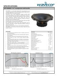
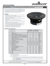
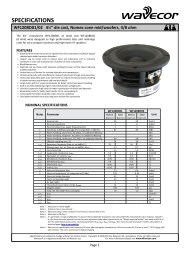
This <strong>paper</strong> uses the specific results obtain for our 7” mid/<br />
woofer WF182BD01. However, all members of the BD<br />
(<strong>Balanced</strong> <strong>Drive</strong>) product line offer the same improvements<br />
and symmetrical motor structure.<br />
The study<br />
Looking at a traditional transducer motor structure<br />
like shown fig. 3a below it is relatively obvious<br />
that the design probably is not ideal. One thing<br />
that comes to mind is that symmetry might be<br />
improved. We have verified this assumption with a<br />
series of simulations shown on the following pages.<br />
So does this lack of symmetry lead to any negative effects<br />
when looking at the performance of the transducer<br />
The concern here is how the poor symmetry of<br />
the magnetic flux density curve over distance will<br />
influence the symmetry of the force factor (Bxl)<br />
as the voice coil moves to different positions.<br />
Ideally the Bxl curve should be constant as a function of<br />
voice coil position or at least symmetrical for movements<br />
in/out.<br />
As an experiment we fed a pure 100 Hz sine wave<br />
into a spectrum analyzer. With no noise or distortion<br />
present we obtained the result shown as the black<br />
100 Hz vertical line in fig. 1. No harmonics present.<br />
Next we manipulated the 100 Hz sine wave by<br />
compressing the positive halves of the sine wave by 50%.<br />
As shown on the following pages this is a realistic largesignal<br />
situation for a non-optimized magnet structure<br />
normally used for loudspeaker transducers. The resulting<br />
spectrum we obtained had added significant even<br />
harmonics, 2nd, 4th, etc. They are the blue lines in fig. 1.<br />
In our example the 2nd harmonic is 17dB below the<br />
fundamental corresponding to around 14% of 2nd order<br />
harmonic distortion. There is additionally noticeable<br />
levels of 4th order harmonics (2.5%). All higher order even<br />
harmonics are present as well although at lower levels.<br />
This means we are claiming that for many existing<br />
transducers the large-signal even order harmonic<br />
distortion caused by non-symmetrical motor structures<br />
could easily reach 10-20% or even higher levels.<br />
The conclusion of our study therefore is that creating<br />
symmetrical motor structures is a great avancement in<br />
loudspeaker transducer design.<br />
Copyright © 2009 by <strong>Wavecor</strong> Ltd., Guangzhou, China. All rights reserved. <strong>Wavecor</strong> ® is a registered trademark of <strong>Wavecor</strong> Ltd.<br />
For more information please visit www.<strong>Wavecor</strong>.com<br />
Page 2
TECHNICAL PAPER<br />
<strong>Wavecor</strong> <strong>Balanced</strong> <strong>Drive</strong> Technology<br />
Results<br />
By introducing the <strong>Balanced</strong> <strong>Drive</strong> Technology <strong>Wavecor</strong><br />
have greatly reduced the even order harmonic distortion<br />
that is present in traditional transducer motor designs.<br />
The resulting improvements in motor symmetry are<br />
shown on the following pages. Within a wide distance<br />
interval almost perfect symmetry is obtained for the flux<br />
density curve and, more importantly, for the Force factor<br />
curve, Bxl.<br />
We specifically used the <strong>Wavecor</strong> mid/woofer model<br />
WF182BD01/02 to generated all the curves shown below<br />
in figs. 4 to 7. Using the <strong>Balanced</strong> <strong>Drive</strong> motor technology<br />
has resulted in a Bxl curve that has non-symmetry better<br />
than +/-5% within a voice coil travel range of +/-12 mm.<br />
The <strong>Balanced</strong> <strong>Drive</strong> design leads to one additional<br />
improvement: Due to the extension of the center pole<br />
the voice coil inductance symmetry is improved too as a<br />
function of the voice coil position.<br />
Level, dB<br />
+20<br />
FREQUENCY SPECTRUM, 100 Hz Sine Wave<br />
+10<br />
0<br />
0dB<br />
-10<br />
-20<br />
-17dB<br />
-30<br />
-32dB<br />
-40<br />
-50<br />
-44dB<br />
-60<br />
-70<br />
-80<br />
-90<br />
-100<br />
10 100 200 400<br />
1k<br />
Frequency, Hz<br />
Fig. 1. Frequency spectrum for a pure 100 Hz sine wave (black vertical line) and the even order higher harmonics (blue<br />
vertical lines) created by non-symmetrical transducer motors.<br />
Copyright © 2009 by <strong>Wavecor</strong> Ltd., Guangzhou, China. All rights reserved. <strong>Wavecor</strong> ® is a registered trademark of <strong>Wavecor</strong> Ltd.<br />
For more information please visit www.<strong>Wavecor</strong>.com<br />
Page 3
TECHNICAL PAPER<br />
<strong>Wavecor</strong> <strong>Balanced</strong> <strong>Drive</strong> Technology<br />
Fig. 2. The magnetic structure of the <strong>Balanced</strong> <strong>Drive</strong> line of <strong>Wavecor</strong> transducers is optimized using<br />
advanced Finite Element Analysis software.<br />
1<br />
1<br />
2 2<br />
3 3<br />
4 4<br />
1: Voice coil windings<br />
2: Top plate<br />
3: T-yoke (center pole & back plate)<br />
4: Magnet<br />
Fig. 3a (left). Cross section of a traditional<br />
motor design.<br />
Fig. 3b (right). Cross section of the <strong>Balanced</strong><br />
<strong>Drive</strong> motor design used for woofers in<br />
the <strong>Wavecor</strong> BD line. The shown motor is<br />
the actual structure used for the <strong>Wavecor</strong><br />
WF182BD01 mid/woofer.<br />
Copyright © 2009 by <strong>Wavecor</strong> Ltd., Guangzhou, China. All rights reserved. <strong>Wavecor</strong> ® is a registered trademark of <strong>Wavecor</strong> Ltd.<br />
For more information please visit www.<strong>Wavecor</strong>.com<br />
Page 4
TECHNICAL PAPER<br />
<strong>Wavecor</strong> <strong>Balanced</strong> <strong>Drive</strong> Technology<br />
B [T]<br />
1.2<br />
Flux density as a function of distance<br />
1.1<br />
1<br />
0.9<br />
DIRECTION OUT<br />
DIRECTION IN<br />
0.8<br />
0.7<br />
VOICE COIL<br />
0.6<br />
0.5<br />
0.4<br />
0.3<br />
0.2<br />
0.1<br />
TOP PLATE<br />
0<br />
20.50<br />
19.48<br />
18.45<br />
17.43<br />
16.40<br />
15.38<br />
14.35<br />
13.33<br />
12.30<br />
11.28<br />
10.25<br />
9.23<br />
8.20<br />
7.18<br />
6.15<br />
5.13<br />
4.10<br />
3.08<br />
2.05<br />
1.03<br />
Distance [mm]<br />
Fig. 4a. Magnetic air gap flux density (B) distribution for a traditional magnet structure as shown fig. 3a.<br />
Notice that the curve is non-symmetrical with higher levels in the direction towards the inside of the magnet<br />
structure.<br />
0.00<br />
-1.03<br />
-2.05<br />
-3.08<br />
-4.10<br />
-5.13<br />
-6.15<br />
-7.18<br />
-8.20<br />
-9.23<br />
-10.25<br />
-11.28<br />
-12.30<br />
-13.33<br />
-14.35<br />
-15.38<br />
-16.40<br />
-17.43<br />
-18.45<br />
-19.48<br />
-20.50<br />
B [T]<br />
1.1<br />
Flux density as a function of distance<br />
1<br />
0.9<br />
DIRECTION OUT<br />
DIRECTION IN<br />
0.8<br />
0.7<br />
0.6<br />
VOICE COIL<br />
0.5<br />
0.4<br />
0.3<br />
0.2<br />
0.1<br />
TOP PLATE<br />
0<br />
20.50<br />
19.48<br />
18.45<br />
17.43<br />
16.40<br />
15.38<br />
14.35<br />
13.33<br />
12.30<br />
11.28<br />
10.25<br />
9.23<br />
8.20<br />
7.18<br />
6.15<br />
5.13<br />
4.10<br />
3.08<br />
2.05<br />
1.03<br />
Distance [mm]<br />
Fig. 4b. Magnetic air gap flux density (B) distribution for the <strong>Wavecor</strong> WF182BD01 mid/woofer. The curve is<br />
almost perfectly symmetrical. The red bar shows the actual WF182BD01 voice coil and its position. The blue<br />
square illustrates the top plate, which is 5mm thick for WF182BD01.<br />
Copyright © 2009 by <strong>Wavecor</strong> Ltd., Guangzhou, China. All rights reserved. <strong>Wavecor</strong> ® is a registered trademark of <strong>Wavecor</strong> Ltd.<br />
For more information please visit www.<strong>Wavecor</strong>.com<br />
0.00<br />
Page 5<br />
-1.03<br />
-2.05<br />
-3.08<br />
-4.10<br />
-5.13<br />
-6.15<br />
-7.18<br />
-8.20<br />
-9.23<br />
-10.25<br />
-11.28<br />
-12.30<br />
-13.33<br />
-14.35<br />
-15.38<br />
-16.40<br />
-17.43<br />
-18.45<br />
-19.48<br />
-20.50
TECHNICAL PAPER<br />
<strong>Wavecor</strong> <strong>Balanced</strong> <strong>Drive</strong> Technology<br />
B [T]<br />
100%<br />
90%<br />
80%<br />
70%<br />
60%<br />
50%<br />
40%<br />
30%<br />
20%<br />
10%<br />
0%<br />
-10%<br />
-20%<br />
-30%<br />
-40%<br />
-50%<br />
-60%<br />
-70%<br />
-80%<br />
-90%<br />
-100%<br />
-110%<br />
-120%<br />
-130%<br />
-140%<br />
-150%<br />
Symmetry check of B curve, non-mirror less mirror curve<br />
relative to non-mirrored B value<br />
DIRECTION OUT<br />
TOP PLATE<br />
DIRECTION IN<br />
20.50<br />
19.48<br />
18.45<br />
17.43<br />
16.40<br />
15.38<br />
14.35<br />
13.33<br />
12.30<br />
11.28<br />
10.25<br />
9.23<br />
8.20<br />
7.18<br />
6.15<br />
5.13<br />
4.10<br />
3.08<br />
2.05<br />
1.03<br />
Distance [mm]<br />
Fig. 5a. Magnetic flux density (B) distribution for a traditional magnet structure as shown fig. 3a. The figure<br />
shows the relative symmetry as the difference when measuring B out/in, held relative to the value outwards.<br />
0.00<br />
-1.03<br />
-2.05<br />
-3.08<br />
-4.10<br />
-5.13<br />
-6.15<br />
-7.18<br />
-8.20<br />
-9.23<br />
-10.25<br />
-11.28<br />
-12.30<br />
-13.33<br />
-14.35<br />
-15.38<br />
-16.40<br />
-17.43<br />
-18.45<br />
-19.48<br />
-20.50<br />
B [T]<br />
100%<br />
90%<br />
80%<br />
70%<br />
60%<br />
50%<br />
40%<br />
30%<br />
20%<br />
10%<br />
0%<br />
-10%<br />
-20%<br />
-30%<br />
-40%<br />
-50%<br />
-60%<br />
-70%<br />
-80%<br />
-90%<br />
-100%<br />
-110%<br />
-120%<br />
-130%<br />
-140%<br />
-150%<br />
Symmetry check of B curve, non-mirror less mirror curve<br />
relative to non-mirrored B value<br />
DIRECTION OUT<br />
TOP PLATE<br />
DIRECTION IN<br />
20.50<br />
19.48<br />
18.45<br />
17.43<br />
16.40<br />
15.38<br />
14.35<br />
13.33<br />
12.30<br />
11.28<br />
10.25<br />
9.23<br />
8.20<br />
7.18<br />
6.15<br />
5.13<br />
4.10<br />
3.08<br />
2.05<br />
1.03<br />
Distance [mm]<br />
Fig. 5b. Magnetic flux density (B) distribution for the <strong>Wavecor</strong> WF182BD01 mid/woofer. The figure shows the<br />
relative symmetry as the difference when measuring B out/in, held relative to the value outwards. Notice the<br />
very significant improvement compared to fig. 5a.<br />
0.00<br />
-1.03<br />
-2.05<br />
-3.08<br />
-4.10<br />
-5.13<br />
-6.15<br />
-7.18<br />
-8.20<br />
-9.23<br />
-10.25<br />
-11.28<br />
-12.30<br />
-13.33<br />
-14.35<br />
-15.38<br />
-16.40<br />
-17.43<br />
-18.45<br />
-19.48<br />
-20.50<br />
Copyright © 2009 by <strong>Wavecor</strong> Ltd., Guangzhou, China. All rights reserved. <strong>Wavecor</strong> ® is a registered trademark of <strong>Wavecor</strong> Ltd.<br />
For more information please visit www.<strong>Wavecor</strong>.com<br />
Page 6
TECHNICAL PAPER<br />
<strong>Wavecor</strong> <strong>Balanced</strong> <strong>Drive</strong> Technology<br />
Fig. 6a. Force factor<br />
(Bxl) as a function of<br />
voice coil position for<br />
a traditional magnet<br />
structure as shown<br />
fig. 3a. The curve is<br />
non-symmetrical and<br />
that the maximum Bxl<br />
is obtained with the<br />
voice coil positioned<br />
1-2 mm below the<br />
center of the air gap.<br />
Bxl [Tm]<br />
7.5<br />
7.0<br />
6.5<br />
6.0<br />
5.5<br />
5.0<br />
4.5<br />
4.0<br />
3.5<br />
DIRECTION OUT<br />
Bxl as a function of voice coil position<br />
DIRECTION IN<br />
Blue: B x l curve<br />
Red: Mirror B xl curve<br />
3.0<br />
2.5<br />
2.0<br />
1.5<br />
TOP PLATE<br />
1.0<br />
0.5<br />
0.0<br />
20.50<br />
19.48<br />
18.45<br />
17.43<br />
16.40<br />
15.38<br />
14.35<br />
13.33<br />
12.30<br />
11.28<br />
10.25<br />
9.23<br />
8.20<br />
7.18<br />
6.15<br />
5.13<br />
4.10<br />
3.08<br />
2.05<br />
1.03<br />
0.00<br />
-1.03<br />
-2.05<br />
-3.08<br />
-4.10<br />
-5.13<br />
-6.15<br />
-7.18<br />
-8.20<br />
-9.23<br />
-10.25<br />
-11.28<br />
-12.30<br />
-13.33<br />
-14.35<br />
-15.38<br />
-16.40<br />
-17.43<br />
-18.45<br />
-19.48<br />
-20.50<br />
Distance [mm]<br />
Fig. 6b. Force factor<br />
(Bxl) as a function<br />
of voice coil position<br />
for the <strong>Wavecor</strong><br />
WF182BD01 <strong>Balanced</strong><br />
<strong>Drive</strong> mid/woofer as<br />
shown fig. 3b. Notice<br />
that the curve is almost<br />
perfect symmetrical<br />
and greatly improved<br />
compared to the<br />
results of a traditional<br />
design as shown fig.<br />
6a.<br />
Bxl [Tm]<br />
7.5<br />
7.0<br />
6.5<br />
6.0<br />
5.5<br />
5.0<br />
4.5<br />
4.0<br />
3.5<br />
3.0<br />
2.5<br />
DIRECTION OUT<br />
Bxl as a function of voice coil position<br />
DIRECTION IN<br />
Blue: B x l curve<br />
Red: Mirror B xl curve<br />
2.0<br />
1.5<br />
TOP PLATE<br />
1.0<br />
0.5<br />
0.0<br />
20.50<br />
19.48<br />
18.45<br />
17.43<br />
16.40<br />
15.38<br />
14.35<br />
13.33<br />
12.30<br />
11.28<br />
10.25<br />
9.23<br />
8.20<br />
7.18<br />
6.15<br />
5.13<br />
4.10<br />
3.08<br />
2.05<br />
1.03<br />
0.00<br />
-1.03<br />
-2.05<br />
-3.08<br />
-4.10<br />
-5.13<br />
-6.15<br />
-7.18<br />
-8.20<br />
-9.23<br />
-10.25<br />
-11.28<br />
-12.30<br />
-13.33<br />
-14.35<br />
-15.38<br />
-16.40<br />
-17.43<br />
-18.45<br />
-19.48<br />
-20.50<br />
Distance [mm]<br />
Copyright © 2009 by <strong>Wavecor</strong> Ltd., Guangzhou, China. All rights reserved. <strong>Wavecor</strong> ® is a registered trademark of <strong>Wavecor</strong> Ltd.<br />
For more information please visit www.<strong>Wavecor</strong>.com<br />
Page 7
TECHNICAL PAPER<br />
<strong>Wavecor</strong> <strong>Balanced</strong> <strong>Drive</strong> Technology<br />
Bxl [Tm]<br />
80%<br />
70%<br />
60%<br />
50%<br />
40%<br />
30%<br />
20%<br />
10%<br />
0%<br />
-10%<br />
-20%<br />
-30%<br />
-40%<br />
-50%<br />
-60%<br />
-70%<br />
-80%<br />
-90%<br />
-100%<br />
-110%<br />
-120%<br />
Symmetry check of Bxl curve, non-mirror less mirror curve<br />
relative to non-mirrored Bxl value<br />
DIRECTION OUT<br />
TOP PLATE<br />
DIRECTION IN<br />
20.50<br />
19.48<br />
18.45<br />
17.43<br />
16.40<br />
15.38<br />
14.35<br />
13.33<br />
12.30<br />
11.28<br />
10.25<br />
9.23<br />
8.20<br />
7.18<br />
6.15<br />
5.13<br />
4.10<br />
3.08<br />
2.05<br />
1.03<br />
Distance [mm]<br />
Fig. 7a. Bxl as a function of voice coil position for a traditional magnet structure as shown fig. 3a. The figure shows<br />
the relative symmetry as the difference when measuring Bxl out/in, held relative to the value outwards.<br />
0.00<br />
-1.03<br />
-2.05<br />
-3.08<br />
-4.10<br />
-5.13<br />
-6.15<br />
-7.18<br />
-8.20<br />
-9.23<br />
-10.25<br />
-11.28<br />
-12.30<br />
-13.33<br />
-14.35<br />
-15.38<br />
-16.40<br />
-17.43<br />
-18.45<br />
-19.48<br />
-20.50<br />
Bxl [Tm]<br />
80%<br />
70%<br />
60%<br />
50%<br />
40%<br />
30%<br />
20%<br />
10%<br />
0%<br />
-10%<br />
-20%<br />
-30%<br />
-40%<br />
-50%<br />
-60%<br />
-70%<br />
-80%<br />
-90%<br />
-100%<br />
-110%<br />
-120%<br />
Symmetry check of Bxl curve, non-mirror less mirror curve<br />
relative to non-mirrored Bxl value<br />
DIRECTION OUT<br />
TOP PLATE<br />
DIRECTION IN<br />
20.50<br />
19.48<br />
18.45<br />
17.43<br />
16.40<br />
15.38<br />
14.35<br />
13.33<br />
12.30<br />
11.28<br />
10.25<br />
9.23<br />
8.20<br />
7.18<br />
6.15<br />
5.13<br />
4.10<br />
3.08<br />
2.05<br />
1.03<br />
Distance [mm]<br />
Fig. 7b. Bxl as a function of voice coil position for the <strong>Wavecor</strong> WF182BD01 mid/woofer. The figure shows the<br />
relative symmetry as the difference when measuring Bxl out/in, held relative to the value outwards. Notice the<br />
very significant improvement compared to fig. 7a.<br />
0.00<br />
-1.03<br />
-2.05<br />
-3.08<br />
-4.10<br />
-5.13<br />
-6.15<br />
-7.18<br />
-8.20<br />
-9.23<br />
-10.25<br />
-11.28<br />
-12.30<br />
-13.33<br />
-14.35<br />
-15.38<br />
-16.40<br />
-17.43<br />
-18.45<br />
-19.48<br />
-20.50<br />
Copyright © 2009 by <strong>Wavecor</strong> Ltd., Guangzhou, China. All rights reserved. <strong>Wavecor</strong> ® is a registered trademark of <strong>Wavecor</strong> Ltd.<br />
For more information please visit www.<strong>Wavecor</strong>.com<br />
Page 8