Installation Instructions for SSS-SPSL Mortise Lock - Best Access ...
Installation Instructions for SSS-SPSL Mortise Lock - Best Access ...
Installation Instructions for SSS-SPSL Mortise Lock - Best Access ...

You also want an ePaper? Increase the reach of your titles
YUMPU automatically turns print PDFs into web optimized ePapers that Google loves.
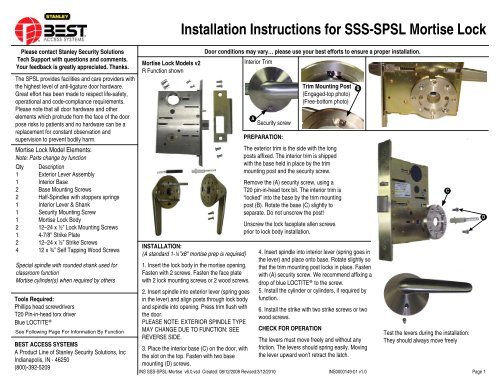
<strong>Installation</strong> <strong>Instructions</strong> <strong>for</strong> <strong>SSS</strong>-<strong>SPSL</strong> <strong>Mortise</strong> <strong>Lock</strong><br />
Please contact Stanley Security Solutions<br />
Tech Support with questions and comments.<br />
Your feedback is greatly appreciated. Thanks.<br />
The <strong>SPSL</strong> provides facilities and care providers with<br />
the highest level of anti-ligature door hardware.<br />
Great ef<strong>for</strong>t has been made to respect life-safety,<br />
operational and code-compliance requirements.<br />
Please note that all door hardware and other<br />
elements which protrude from the face of the door<br />
pose risks to patients and no hardware can be a<br />
replacement <strong>for</strong> constant observation and<br />
supervision to prevent bodily harm.<br />
<strong>Mortise</strong> <strong>Lock</strong> Model Elements:<br />
Note: Parts change by function<br />
Qty Description<br />
1 Exterior Lever Assembly<br />
1 Interior Base<br />
2 Base Mounting Screws<br />
2 Half-Spindles with stoppers springs<br />
1 Interior Lever & Shank<br />
1 Security Mounting Screw<br />
1 <strong>Mortise</strong> <strong>Lock</strong> Body<br />
2 12–24 x ½” <strong>Lock</strong> Mounting Screws<br />
1 4-7/8" Strike Plate<br />
2 12–24 x ½” Strike Screws<br />
4 12 x ¾” Self Tapping Wood Screws<br />
Special spindle with rounded shank used <strong>for</strong><br />
classroom function<br />
<strong>Mortise</strong> cylinder(s) when required by others<br />
Tools Required:<br />
Phillips head screwdrivers<br />
T20 Pin-in-head torx driver<br />
Blue LOCTITE®<br />
See Following Page For In<strong>for</strong>mation By Function<br />
BEST ACCESS SYSTEMS<br />
A Product Line of Stanley Security Solutions, Inc<br />
Indianapolis, IN - 46250<br />
(800)-392-5209<br />
<strong>Mortise</strong> <strong>Lock</strong> Models v2<br />
R Function shown<br />
INSTALLATION:<br />
(A standard 1-¼”x8" mortise prep is required)<br />
1. Insert the lock body in the mortise opening.<br />
Fasten with 2 screws. Fasten the face plate<br />
with 2 lock mounting screws or 2 wood screws.<br />
2. Insert spindle into exterior lever (spring goes<br />
in the lever) and align posts through lock body<br />
and spindle into opening. Press trim flush with<br />
the door.<br />
PLEASE NOTE: EXTERIOR SPINDLE TYPE<br />
MAY CHANGE DUE TO FUNCTION: SEE<br />
REVERSE SIDE.<br />
3. Place the interior base (C) on the door, with<br />
the slot on the top. Fasten with two base<br />
mounting (D) screws.<br />
Door conditions may vary… please use your best ef<strong>for</strong>ts to ensure a proper installation.<br />
Interior Trim<br />
A<br />
Security screw<br />
Trim Mounting Post<br />
(Engaged-top photo)<br />
(Free-bottom photo)<br />
PREPARATION:<br />
The exterior trim is the side with the long<br />
posts affixed. The interior trim is shipped<br />
with the base held in place by the trim<br />
mounting post and the security screw.<br />
Remove the (A) security screw, using a<br />
T20 pin-in-head torx bit. The interior trim is<br />
“locked” into the base by the trim mounting<br />
post (B). Rotate the base (C) slightly to<br />
separate. Do not unscrew the post!<br />
Unscrew the lock faceplate allen screws<br />
prior to lock body installation.<br />
4. Insert spindle into interior lever (spring goes in<br />
the lever) and place onto base. Rotate slightly so<br />
that the trim mounting post locks in place. Fasten<br />
with (A) security screw. We recommend affixing a<br />
drop of blue LOCTITE® to the screw.<br />
5. Install the cylinder or cylinders, if required by<br />
function.<br />
6. Install the strike with two strike screws or two<br />
wood screws.<br />
CHECK FOR OPERATION<br />
The levers must move freely and without any<br />
friction. The levers should spring easily. Moving<br />
the lever upward won’t retract the latch.<br />
B<br />
Test the levers during the installation:<br />
They should always move freely<br />
INS <strong>SSS</strong>-<strong>SPSL</strong>-<strong>Mortise</strong> v6.0.vsd Created: 08/12/2008 Revised:3/12/2010 INS0000149-01 v1.0 Page 1<br />
C<br />
D
INSTALLATION INFORMATION<br />
PASSAGE MODELS: ON<br />
<strong>Installation</strong> is identical to<br />
cylindrical latch, except mortise<br />
lock body is used and mounting<br />
screws are on the diagonal.<br />
ASYLUM MODELS: W1-W2<br />
Install cylinders with <strong>Best</strong> “C4”<br />
cams. Use the appropriate rings.<br />
STOREROOM MODELS: D<br />
Install cylinders with <strong>Best</strong> “C4”<br />
cams. Use the appropriate rings.<br />
Do not install a spindle in the<br />
exterior trim.<br />
CLASSROOM FUNCTION<br />
MODELS: R - INL<br />
Install cylinders with <strong>Best</strong> “C4”<br />
cams. Use the appropriate rings.<br />
The spindle with the rounded<br />
section must be used on the<br />
exterior side of the door.<br />
LT - BATHROOM PRIVACY<br />
FUNCTION<br />
1 Interior Anti-Ligature Thumb turn<br />
1 Exterior coin turn cylinder<br />
Same Elements as R – INL<br />
(See <strong>SPSL</strong> Privacy <strong>Installation</strong><br />
<strong>Instructions</strong>)<br />
BEST ACCESS SYSTEMS<br />
A Product Line of Stanley Security<br />
Solutions, Inc<br />
Indianapolis, IN - 46250<br />
(800)-392-5209<br />
PASSAGE MODEL ELEMENTS<br />
Qty Description ON<br />
1 Exterior Escutcheon Assembly<br />
1 Interior Escutcheon Assembly<br />
(Shipped with mounting screws attached)<br />
2 Half-Spindles With Springs<br />
1 <strong>Mortise</strong> <strong>Lock</strong> Body: Passage<br />
(shipped with face plate attached)<br />
2 <strong>Lock</strong> Mounting Screws<br />
1 4-7/8" Strike Plate<br />
2 Strike Screws<br />
4 Wood Screws<br />
W10-W20-ASYLUM<br />
Same Elements as W1-W2<br />
Less Interior Escutcheon Assembly<br />
A-OFFICE FUNCTION<br />
1 Interior Anti-Ligature thumb turn<br />
Same Elements as R - INL<br />
(See <strong>SPSL</strong> Privacy <strong>Installation</strong> <strong>Instructions</strong>)<br />
ADDITIONAL INFORMATION FOR MORTISE LOCK MODELS<br />
Cylinder(s) used in asylum function not shown. All asylum<br />
function locks are prepared <strong>for</strong> single or double sided<br />
operation.<br />
ASYLUM MODEL ELEMENTS<br />
Qty Description W1-W2<br />
1 Exterior Escutcheon Assembly<br />
1 Interior Escutcheon Assembly<br />
(Shipped with mounting screws attached)<br />
1 <strong>Mortise</strong> <strong>Lock</strong> Body: Storeroom<br />
2 <strong>Lock</strong> Mounting Screws<br />
1 4-7/8" Strike Plate<br />
2 Strike Screws<br />
4 Wood Screws<br />
CLASSROOM MODEL ELEMENTS<br />
Qty Description R - INL<br />
1 Exterior Escutcheon Assembly<br />
1 Interior Escutcheon Assembly<br />
(Shipped with mounting screws attached)<br />
1 Half-Spindle With Spring<br />
1 Half-Spindle With Rounded Shank<br />
1 <strong>Mortise</strong> <strong>Lock</strong> Body: Classroom<br />
2 <strong>Lock</strong> Mounting Screws<br />
1 4-7/8" Strike Plate<br />
2 Strike Screws<br />
4 Wood Screws<br />
<strong>SSS</strong>-<strong>SPSL</strong> <strong>Installation</strong> <strong>Instructions</strong><br />
CLASSROOM FUNCTION OPERATION:<br />
The exterior lever never becomes rigid. When the classroom<br />
function is engaged, the lever will move upward and downward, but<br />
will not retract the latch.<br />
The latch can be retracted after the classroom mode<br />
is disengaged.<br />
SPECIAL R<br />
Exterior Spindle<br />
Cylinder used in<br />
classroom function not<br />
shown.<br />
Ensure that the spindle hubs on both sides of the mortise lock<br />
body are properly aligned by using the alignment marks.<br />
STOREROOM MODEL ELEMENTS<br />
Qty Description D<br />
1 Exterior Escutcheon Assembly<br />
1 Interior Escutcheon Assembly<br />
(Shipped with mounting screws attached)<br />
1 Half-Spindles With Spring<br />
1 <strong>Mortise</strong> <strong>Lock</strong> Body: Storeroom)<br />
2 <strong>Lock</strong> Mounting Screws<br />
1 4-7/8" Strike Plate<br />
2 Strike Screws<br />
4 Wood Screws<br />
INS <strong>SSS</strong>-<strong>SPSL</strong>-<strong>Mortise</strong> v6.0.vsd Created: 08/12/2008 Revised:3/12/2010 INS0000149-01 v1.0 Page 2


![B.A.S.I.S. G Service Manual [T63300] - Best Access Systems](https://img.yumpu.com/48375082/1/190x245/basis-g-service-manual-t63300-best-access-systems.jpg?quality=85)