

Chip monolithic ceramic capacitors
Chip monolithic ceramic capacitors
Chip monolithic ceramic capacitors

Create successful ePaper yourself
Turn your PDF publications into a flip-book with our unique Google optimized e-Paper software.
!Note • This !Note PDF catalog • Please is downloaded read rating and from !CAUTION the website (for of Murata storage, Manufacturing operating, rating, co., ltd. soldering, Therefore, mounting it’s specifications and handling) are in subject this catalog to change to prevent or our smoking products and/or in it may burning, be discontinued etc. without advance notice. Please check with our<br />
sales representatives • This catalog or product has only engineers typical specifications before ordering. because there is no space for detailed specifications. Therefore, please approve our product specifications or transact the approval sheet for product specifications before ordering.<br />
• This PDF catalog has only typical specifications because there is no space for detailed specifications. Therefore, please approve our product specifications or transact the approval sheet for product specifications before ordering.<br />
C02E.pdf<br />
05.12.14<br />
Specifications and Test Methods<br />
Continued from the preceding page.<br />
No. Item Specifications Test Method<br />
6<br />
10<br />
Adhesive Strength<br />
of Termination<br />
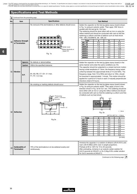
No removal of the terminations or other defects should occur.<br />
Fig. 1a<br />
c<br />
a<br />
Solder resist<br />
Baked electrode or<br />
copper foil<br />
Solder the capacitor on the test jig (glass epoxy board) shown<br />
in Fig. 1a using an eutectic solder. Then apply 10N * force in<br />
parallel with the test jig for 10T1sec.<br />
The soldering should be done either with an iron or using the<br />
reflow method and should be conducted with care so that the<br />
soldering is uniform and free of defects such as heat shock.<br />
*5N : GRp15/GRM18, 2N : GRp33<br />
Type a b c<br />
0.3 0.9<br />
0.4 1.5<br />
1.0 3.0<br />
1.2 4.0<br />
2.2 5.0<br />
2.2 5.0<br />
3.5 7.0<br />
4.5 8.0<br />
GRp03<br />
GRp15<br />
GRM18<br />
GRM21<br />
GRM31<br />
GRM32<br />
GRM43<br />
GRM55<br />
0.3<br />
0.5<br />
1.2<br />
1.65<br />
2.0<br />
2.9<br />
3.7<br />
5.6<br />
11<br />
Vibration<br />
Appearance<br />
Capacitance<br />
D.F.<br />
No defects or abnormalities<br />
Within the specified tolerance<br />
B1, B3, R6, C7, C8 : 0.1 max.<br />
F1, F5 : 0.2 max.<br />
Solder the capacitor on the test jig (glass epoxy board) in the<br />
same manner and under the same conditions as (10).<br />
The capacitor should be subjected to a simple harmonic motion<br />
having a total amplitude of 1.5mm, the frequency being varied<br />
uniformly between the approximate limits of 10 and 55Hz. The<br />
frequency range, from 10 to 55Hz and return to 10Hz, should<br />
be traversed in approximately 1 minute. This motion should be<br />
applied for a period of 2 hours in each 3 mutually perpendicular<br />
directions (total of 6 hours).<br />
12<br />
Deflection<br />
No cracking or marking defects should occur.<br />
R230<br />
20 50 Pressurizing<br />
speed : 1.0mm/sec.<br />
Pressurize<br />
Capacitance meter<br />
45 45<br />
Fig.3a<br />
Flexure : V1<br />
Solder the capacitor on the test jig (glass epoxy board) shown<br />
in Fig. 2a using an eutectic solder. Then apply a force in the<br />
direction shown in Fig. 3a for 5T1 sec. The soldering should be<br />
done either with an iron or using the reflow method and should<br />
be conducted with care so that the soldering is uniform and free<br />
of defects such as heat shock.<br />
b<br />
ø4.5<br />
TU WXYZ [\] _`¥¦ ¨©ª« ¬® °±, TU X¥¦ ©, VWZ[§¨«¬ Q TU¢ ¥¦ YZ^ª«¯VZ[§«¬ QRSUVWZ<br />
]^¢£¤¦§¨« Z]^«®¯STW¤¥¨<br />
®¯ Y]^ª®¯<br />
U¦UY¦ªc<br />
a<br />
100<br />
Fig. 2a<br />
(GRp03, GRp15 : t : 0.8mm)<br />
Type a b c<br />
GRp03<br />
GRp15<br />
GRM18<br />
GRM21<br />
GRM31<br />
GRM32<br />
GRM43<br />
GRM55<br />
0.3<br />
0.4<br />
1.0<br />
1.2<br />
2.2<br />
2.2<br />
3.5<br />
4.5<br />
0.9<br />
1.5<br />
3.0<br />
4.0<br />
5.0<br />
5.0<br />
7.0<br />
8.0<br />
0.3<br />
0.5<br />
1.2<br />
1.65<br />
2.0<br />
2.9<br />
3.7<br />
5.6<br />
(in mm)<br />
40<br />
t : 1.6mm<br />
13<br />
Solderability of<br />
Termination<br />
75% of the terminations is to be soldered evenly and<br />
continuously.<br />
Immerse the capacitor in a solution of ethanol (JIS-K-8101) and<br />
rosin (JIS-K-5902) (25% rosin in weight proportion) .<br />
Preheat at 80 to 120D for 10 to 30 seconds.<br />
After preheating, immerse in an eutectic solder solution for<br />
2T0.5 seconds at 230T5D or Sn-3.0Ag-0.5Cu solder solution<br />
for 2T0.5 seconds at 245T5°C.<br />
Continued on the following page.<br />
36