RM410 GLOBE Radial Piston Air Motor - PT Hydraulics
RM410 GLOBE Radial Piston Air Motor - PT Hydraulics
RM410 GLOBE Radial Piston Air Motor - PT Hydraulics

Create successful ePaper yourself
Turn your PDF publications into a flip-book with our unique Google optimized e-Paper software.
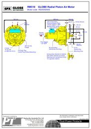
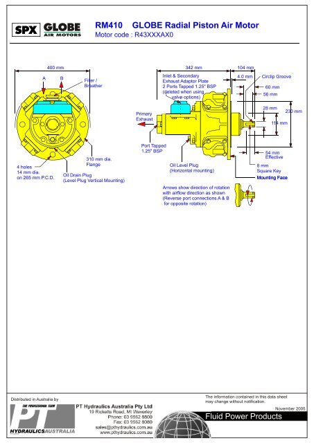
SPX FLUID POWER <strong>RM410</strong> <strong>GLOBE</strong> <strong>Radial</strong> <strong>Piston</strong> <strong>Air</strong> <strong>Motor</strong><br />
<strong>Motor</strong> code : R43DXXAX0<br />
A<br />
400 mm 342 mm 104175 mm mm 104 mm<br />
B<br />
Filler /<br />
Breather<br />
Inlet & Secondary<br />
Exhaust Adaptor Plate<br />
2 Ports Tapped 1.25" BSP<br />
(deleted when using<br />
valve options)<br />
Circlip Groove<br />
60 mm<br />
56 mm<br />
Primary<br />
Exhaust<br />
28 mm<br />
114 mm<br />
230 mm<br />
28.01 mm<br />
28.00 dia.<br />
4 holes<br />
14 mm dia.<br />
on 265 mm P.C.D.<br />
310 mm dia.<br />
Flange<br />
Oil Drain Plug<br />
(Level Plug Vertical Mounting)<br />
Port Tapped<br />
1.25" BSP<br />
Oil Level Plug<br />
(Horizontal mounting)<br />
Arrows show direction of rotation<br />
with airflow direction as shown<br />
(Reverse port connections A & B<br />
for opposite rotation)<br />
See Accessories - Parking Brakes<br />
for overall dimensions and fixing<br />
54 mm<br />
Effective details of parking brake.<br />
8 mm<br />
Mounting Face<br />
Square Key<br />
Mounting Face
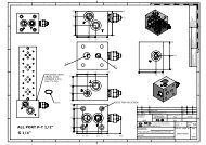
SPX FLUID POWER<br />
<strong>RM410</strong><br />
Parking Brakes<br />
The brake module bolts directly onto the motor mounting face and has exactly the same interface as the motor<br />
As shown on the drawing below, the brake consists of two spring applied shoes pressed against a central hub.<br />
These shoes are released by applying air pressure to the cylinder / piston assembly. The brake torque can be varied<br />
by means of two spring adjusters but it is normally set so that a pilot pressure of 4.1 bar (60 p.s.i.) will fully release it.<br />
Pressures below this level will progressively reduce the braking torque available. The brakes are set at the plant but it<br />
the operating pressure of the brake MUST be set on installation to suit the individual application.<br />
175 mm 104 mm<br />
16 mm 37 mm<br />
4.0 mm<br />
206 mm<br />
340 mm<br />
(Adjustable)<br />
Brake line inlet compression<br />
fitting for 5/16" O/D tubing<br />
Brake spring adjusters<br />
Pilot air<br />
connection<br />
<strong>Motor</strong><br />
interface<br />
28.01 mm<br />
28.00 mm<br />
Note - same mounting<br />
interface as motor<br />
31.01 mm<br />
30.71 mm<br />
8.00 mm<br />
7.94 mm<br />
View on shaft end<br />
Mounting<br />
face<br />
230.00 mm<br />
229.93 mm<br />
Mounting spigot<br />
305 mm diameter flange<br />
4 holes 14 mm diameter<br />
on 265 mm P.C.D.<br />
Max. bolt length 40 mm<br />
This is a Parking Brake ONLY. It MUST NOT be used in a Dynamic application<br />
Circuit A<br />
Circuit A Applies to braked motors<br />
supplied without control valving.<br />
The unit will be fitted with a shuttle valve<br />
to allow brake operation for dual rotation.<br />
Circuit B<br />
Circuit B Units supplied with hand (HCV)<br />
controlled reversible valves. If trips are<br />
required they must be of the mechanical<br />
style (csustomer's supply).<br />
Circuit C<br />
Circuit C Units supplied with remotely<br />
controlled valves. When override trips are<br />
required, they must be superimposed in<br />
the signal line close to the motor unit<br />
and be of the 3 way style (Signal lines<br />
cut and exhausted in the tripped position.)
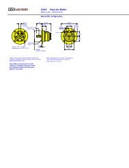
SPX FLUID POWER<br />
REMOTE CONTROL VALVE<br />
<strong>RM410</strong><br />
Inlet port<br />
1-1/4" BSP<br />
Control Valve Options<br />
280 mm<br />
160 mm 72 mm<br />
Secondary exhaust<br />
port 1-1/4" BSP<br />
Port Datum<br />
114 mm<br />
HAND CONTROL VALVE<br />
<strong>Motor</strong> centre line<br />
365 mm<br />
One pilot port each end 1/4" BSP<br />
Caps may be positioned with port<br />
at top, bottom or either side<br />
160 mm<br />
Inlet port<br />
1-1/4" BSP<br />
75 mm<br />
Mounts onto<br />
motor port face<br />
Port Datum<br />
198 mm<br />
112 mm<br />
Operating lever can be<br />
fitted on either end<br />
Exhaust port<br />
1-1/4" BSP<br />
72 mm<br />
22 mm<br />
Port<br />
Face<br />
This range of bolt on valves offers very sensitive speed and directional control. One frictional matched spool and sleeve<br />
assembly is offered with two alternative means of actuation.<br />
CONFIGURATION<br />
As standard these valves can be supplied with either EQUAL POWER OR BIASED POWER spools, the latter is suitable for<br />
hoisting applications (normal power for lifting - reduced power for lowering).<br />
The direction of reduced power must be stated when ordering CW or CCW, when viewed on the output shaft of the motor or<br />
geared motor.<br />
1. REMOTELY CONTROLLED (RCV) - This option is usually controlled from a remote position by one of the PC series or<br />
LC2 remote controllers. A variable air pilot signal is applied to either end of the valve spool, depending on the required<br />
direction of motor rotation. The pilot pressure range is between 1.4 bar (20 psi) and 4.8 bar (70 psi), increased pilot pressure<br />
gives increased speed. The valve is spring centred to neutral.<br />
2. HAND CONTROLLED (HCV) - The control valve spool is operated directly by a lver mechanism. Speed increase is<br />
obtained as the lever is moved in either direction from the centre (neutral) position.<br />
PRESSURE DROP - Minimal pressure drop will be experienced through the valves, having the effect of maintaining the output<br />
torque whilst reducing the motor output speed by approximately 10-15% at 6 bar (90 psi) at maximum power. The starting<br />
torque remains unaffected.
SPX FLUID POWER<br />
Remote Controllers<br />
PENDANT CONTROLS (PC2, 4 or 6)<br />
The PC2, 4 and 6 remote controllers are designed specifically for use with the remote control valves (RCV range). They provide<br />
the correct range of pilot pressure required to operate the RCV units, and give excellent control of motor speed. The PC2 is<br />
used to control one (hoist) motor; the PC4 can control two motors independently (say hoist and long travel); the PC6 can<br />
control three motors independently (hoist, long travel, traverse. <strong>Motor</strong>s of different sizes can be controlled from the same unit.<br />
Control line lengths of 36m (120ft) give excellent response. For distances in excess of this consult SPX Fluid Power or<br />
distributor. The control lines are small bore eliminating the need for large capacity air supply lines between motor and<br />
controller. If required, supply pressure can be taken from the tapping on the RCV.<br />
MARINE VERSIONS AVAILABLE. PC2M, PC4M or PC6M.<br />
Supply<br />
Supply<br />
3 4<br />
Supply<br />
3 4<br />
Exhaust<br />
Signal output To other<br />
stations<br />
1 2<br />
Signal outputs<br />
76 mm<br />
Support<br />
Wire<br />
1 2<br />
Signal outputs<br />
5 6<br />
1 2<br />
Signal outputs<br />
Supply<br />
Circuit schematic for 1<br />
signal output port<br />
Support<br />
Wire<br />
1 2<br />
3 4<br />
5 6<br />
200 mm<br />
1 2<br />
3 4<br />
237 mm<br />
1 2<br />
Controls 1 motor<br />
PC2<br />
All connections 1/8" N<strong>PT</strong><br />
Controls 2 motors<br />
PC4<br />
280 mm<br />
Controls 3 motors<br />
PC6<br />
120 mm<br />
A<br />
E,F<br />
B<br />
LEVER CONTROL<br />
(LC2)<br />
MARINE STYLE (LC2M)<br />
A<br />
28°<br />
B<br />
28°<br />
245 mm<br />
7 mm<br />
15 mm<br />
G,H<br />
Circuit Symbol<br />
Lever Control Valve<br />
70 mm<br />
80 mm<br />
63.5 mm<br />
F<br />
H<br />
8 mm<br />
E<br />
G<br />
37.5 mm<br />
Note:<br />
H and G are alternative supply ports.<br />
A and B are outlet ports.<br />
Plug alternative ports not connected.<br />
E and F are exhaust ports.<br />
All ports are 1/8" BSP<br />
A<br />
B<br />
108 mm<br />
3 holes 5 mm diameter<br />
2 holes 5 mm diameter
SPX FLUID POWER<br />
<strong>RM410</strong><br />
<strong>Air</strong> <strong>Motor</strong> Foot Bracket<br />
372 mm<br />
<strong>Motor</strong> or brake<br />
interface<br />
215 mm<br />
214.5 mm<br />
2 holes<br />
20 mm dia.<br />
228 mm<br />
330 mm<br />
21 mm<br />
52 mm 22 mm
SPX FLUID POWER<br />
INSTALLATION<br />
1. Mounting Positions<br />
The motor is normally mounted in a horizontal position with<br />
the filler / breather plug towards the top (Fig. 1) It may also<br />
be mounted with the shaft vertically downwards (Fig. 2). As<br />
supplied the motors have been run up and tested using<br />
protective oil and then drained for transit.<br />
It is vital that each motor is re-filled to the correct oil level<br />
as shown below.<br />
The RM110 - 310 motors have a dipstick for vertical<br />
mounting (Fig. 2) and the lower mark on this dipstick<br />
provides the oil level. Oil levels are achieved on motors in<br />
the horizontal postion by filling to the plugs marked 60<br />
(RM110 - 410 models) and plug 26 (fitted in housing 3<br />
RM510 - 610 models).<br />
(numbers indicate parts on exploded view)<br />
The vertical oil level position for the <strong>RM410</strong>, RM510 and<br />
RM610 motors is a combined horizontal drain and vertical<br />
level plug (part number 26)<br />
To fill motors with oil remove the combined breather<br />
and oil filler plug part number 46. Ensure breather<br />
plug is in the vertical position. It may be necccessary<br />
to fit an elbow between the breather plug and the<br />
motor (see Fig. 2).<br />
2. Recommended Lubricants for normal<br />
ambient temperature (0 - 32 deg. C.)<br />
Shell<br />
B.P.<br />
Esso<br />
Regent<br />
Castrol<br />
Mobil<br />
Crankcase<br />
TELLUS 100<br />
ENERGOL HL175<br />
NUTO H.64<br />
REGAL PE.RO<br />
HYSPIN 175<br />
D.T.E. EXTRA HEAVY<br />
RM <strong>Air</strong> <strong>Motor</strong><br />
Installation / Maintenance / Servicing<br />
<strong>Air</strong>line<br />
TELLUS 37<br />
ENERGOL HLP65<br />
FANOX 38<br />
RANDO 'A'<br />
HYSPIN 70<br />
ALMO OIL NO. 1<br />
For extremes of ambient temperatures consult the<br />
manufactures<br />
3. <strong>Air</strong> Inlet<br />
The motor is normally supplied with inlet / exhaust adaptor<br />
plate (72). All motors are reversible.<br />
4. <strong>Air</strong> Supply. Maximum Working<br />
Pressure 8 bar - 120 psi<br />
The air supply must be clean and free from moisture. An<br />
airline filter and mist lubricator should be incorporated in the<br />
air supply line, located immediately before the motor. If the<br />
rated performance of the motor is to be obtained all valves<br />
and pipework must be of adequate size. Valves should be<br />
sited as close as possible to the motor.<br />
For short pipe runs e.g. up to 2 metres the supply line<br />
should be the same size as the motor ports and larger for<br />
longer runs.<br />
5. Fitting<br />
Mount motor in operating position. Check oil level. (as 1<br />
above). Before connecting to the air supply blow out the air<br />
lines to remove any loose scale, swarf or abrasive dust<br />
which may be present.<br />
Remove the red plastic dust-caps and the 'O' ring seal (45).<br />
For unidirectional operation check the required direction of<br />
rotation and connect the air supply line to the appropriate<br />
port on the inlet / exhaust adaptor plate (72) leaving the other<br />
port open or pipe downwards if exposed to the atmosphere.<br />
<strong>Motor</strong> Mounting Positions<br />
A<br />
Breather / Filler Plug<br />
B<br />
Horizontal Oil Level<br />
RM110 - 210 - 310 - 410<br />
Fit elbow and<br />
breather plug<br />
(for ease of<br />
filling in the<br />
vertical position)<br />
Dipstick<br />
(Only fitted on<br />
RM110 - 210 - 310)<br />
Fig. 1 Fig. 2<br />
Shaft rotation as shown with inlet 'A'<br />
Reverse rotation is obtained with inlet at 'B'<br />
Note! When first running the motor some light oil should be<br />
injected into the inlet connection to ensure adequate<br />
lubrication until the airline lubrication is established.<br />
Maintenance<br />
6. <strong>Air</strong> Supply<br />
The air filter should be drained regularly and examined for<br />
clogging of the element.<br />
The air line lubricator should be replenished as required<br />
and set to give 3-4 drops per minute RM110<br />
4-5 drops per minute RM210<br />
5-6 drops per minute RM310<br />
6-8 drops per minute <strong>RM410</strong><br />
6-8 drops per minute RM510<br />
8-10 drops per minute RM610<br />
Double the above drip rate if intermittent operation.<br />
7. <strong>Motor</strong><br />
The oil level in the motor casing must be maintained. The<br />
frequency of replenishment will depend on the application<br />
and usage.<br />
The motor case should be drained and refilled after 25<br />
hours of initial running and every 200 hours thereafter or<br />
sooner if found neccessary e.g. (contamination of oil by<br />
water from the air line.)<br />
Fault Finding<br />
1. The RM series motors are designed to perform at their<br />
rated capacities for the long periods of time. Faults can<br />
develop for the following reasons:<br />
(A) Lack of lubrication. This will leave to rapid wear, internal<br />
seizure, loss of power or excessive air leakage.<br />
(B) Faults in the air supply system:<br />
1. failure to remove the plastic protective dust caps<br />
2. insufficient air pressure at the motor caused by (a) supply<br />
pipe line or valve too small (b) if the exhaust is piped away<br />
ecessive back pressure due to small bore pipes (c)<br />
compressor of insufficient capacity (d) clogged airline filter<br />
(e) the air pressure should remain at the required pressure<br />
when the motor is operating at full potential.<br />
If the air pressure reduces considerably from the stationary<br />
to the rotating conditions then the supply line or the<br />
compressed air avaiable is inadequate for the service<br />
operation of the motor.<br />
Oil<br />
Level<br />
The motor should not be allowed to race. Always operate<br />
within the catalogue speed curves.<br />
The motor should always be supplied with clean moisture<br />
free and lubricated air. The better the quality of the air the<br />
less attention will be required to the motor unit.<br />
y<br />
THE PROFESSIONAL TEAM<br />
The information contained in this data<br />
sheet may vary without notification<br />
HYDRAULICSAUSTRALIA<br />
November 2005
SPX FLUID POWER<br />
8. SERVICING<br />
A. Preperation for stripping<br />
Remove the motor from its operating position to a clean<br />
working surface ready for stripping, externally clean the<br />
motor ready for opening.<br />
Drain the oil from the motor casing by removing the drain<br />
plug (26).<br />
Stripping and re-assembly will be simplified if the crankshaft<br />
(20/A/B) or output shaft (67) RM510 and RM610 is held<br />
vertically in a soft-jawed vice or supported on a suitable<br />
packing to raise the shaft clear of the working surface.<br />
B. Removal of Rotary Valve Housing assembly<br />
Remove inlet / exhaust adaptor plate (72) or control valve (if<br />
fitted).<br />
Remove valve cover (51)<br />
Release bolts (38) and valve bush housing (3) can be<br />
eased upward.<br />
On RM110 to 410 motors remove grub screw (49) together<br />
with the valve side balance weight (number 35).<br />
All motors - carefully remove rotary valve (2) from the<br />
housing (3). This can generally done from the inside<br />
outwards and inspect both the rotary valve and the housing<br />
for wear. The normal clearance at manufacture between<br />
these two components is 0.002 - 0.003" (0.05 - 0.075 mm).<br />
Excessive wear will cause air leakages and loss of<br />
efficiency of the unit.<br />
RM 110 <strong>Motor</strong>s only<br />
Lift the spacing washers (31/34) out. Slightly rotate the shaft<br />
backwards and forwards and inspect the amount of wear<br />
which is present on the big end assembly. Remove the top<br />
retaining ring (part no. 74) . All the connecting rods can then<br />
be lifted upwards and pushed outwards towards the<br />
cylinders. Remove cylinder bolts (37) and the entire piston<br />
assembly can be withdrawn from the motor unit.<br />
<strong>Motor</strong>s RM 210 / 310 / 410<br />
These units are of the king rod variety and again it is wise to<br />
slightly rotate the crankshaft (part no. 20 A/B) in either<br />
direction to test any excessive wear on either the king rod<br />
bearing or the pivot pins (part no. 29). Having first removed<br />
the outer spacing washer (31/34) withdraw pivot pins (part<br />
no. 29). This procedure is usually done with a bent rod<br />
withdrawing the pins from the inside outwards. Remove all<br />
cylinder cap bolts (part 37) and by pushing the queen rods<br />
(part 30) outwards the entire piston and rod asembly can be<br />
removed from the motor.<br />
Turn the motor unit over to extract the crank bearing or<br />
bearings (part no. 48). The main king rod (part no. 12) can<br />
then be lifted upwards and tilted over the top of the<br />
crankshaft. Remove the main king rod, piston and cylinder<br />
from the motor. Remove the output shaft circlip (14), spacer<br />
(15) and shims (16). Remove the counter sunk bolts (52)<br />
holding the output flange (24 / A B) on to the engine case<br />
(part no. 27). The engine case (27) can be removed.<br />
Drift the crankshaft inwards from the flange plate (24A). To<br />
remove the outer shaft bearings (55 and 56) drift to their<br />
respective sides as they are located inwardly on the two<br />
circlips (part no. 18).<br />
RM 510 and 610 <strong>Motor</strong>s<br />
Remove bolts (58) holding the output shaft assembly.<br />
Remove bolts (57) and the output flange (24 A/B). This will<br />
then expose the inside of the motor. Turn the crankshaft so<br />
that one rod is at T.D.C. Remove that cylinder, the retaining<br />
circlip and gudgeon pin. Push out from the piston and the<br />
entire assembly can be removed.<br />
RM <strong>Air</strong> <strong>Motor</strong><br />
Installation / Maintenance / Servicing<br />
RM 510 and 610 <strong>Motor</strong>s (continued)<br />
Repeat this procedure in turn until all the pistons have been<br />
removed. On this motor the balance weight and crank<br />
assembly is built as one item and this can now be removed.<br />
Remove locking nut (22) and the tapered pin (21). Both<br />
balance weights (part no. 20A and 20B) can now be<br />
disengaged.<br />
This will expose the king rod and queen rod assembly. To<br />
remove the queen rod remove the pivot pin (29).<br />
All <strong>Motor</strong>s<br />
Inspect the clearance of the pivot pins (29) in queen rod (30)<br />
and king rod(12). Inspect the gudgeon pin in both the piston<br />
and all rods. Check for wear on the main crankshaft (20A,<br />
20B) and on the main big end bearing (no. 48). The wear in<br />
the cylinder bores can be checked by removing each<br />
compression ring (10) and pushing it into the cylinder bore<br />
(8). The ring gap should be in the region of 0.003 to 0.004"<br />
(0.075 - 0.010 mm). Bore wear cause loss of power and<br />
inject high pressure air into the case & oil could be ejected<br />
from the breather plug (part no. 46). All other parts should be<br />
thoroughly cleaned and inspected for wear.<br />
Spare parts can be found from the spare listings.<br />
The motor number and its code should be incorporated in<br />
any spares order. This is always stamped on the main<br />
flange plate (24) located near the breather plug hole 46, i.e.<br />
230 Hx.<br />
SPX provide a seal kit for each motor and it is strongly<br />
recommended that new oil seals, seals and gaskets are<br />
used throughout.<br />
9. ASSEMBLY PROCEDURE<br />
All parts should be clean and liberally coated with oil.<br />
RM 510 and RM 610 motor only<br />
Assemble the spacing washer (13) on to the crankshaft<br />
outer section locating the dowell pin (23). Assemble bearing<br />
(48) and the king rod (12). Assemble all four queen rods<br />
(part no. 30) into the king rod (12) locating with pivot pins<br />
(no. 29).<br />
Fit final location washer (13) to close the assembly.<br />
Ensure that the drive peg (23) is fitted on to the inner<br />
balance weight (20 A / B). Closed together and finally rotated<br />
to locate correctly by passing a 12 mm dia. bar between the<br />
holes marked X and Y on the drawings. Once this assembly<br />
is located the locking dowell (21) and its nut can be<br />
assembled, remove the 12 mm bar and ensure that the<br />
mechanism is free. Locate assembly into open engine<br />
case. Ensure each rod projects into its correct cylinder.<br />
Rotate the unit so that the main king rod comes to top dead<br />
centre, fit the piston and gudgeon pin, ensure gudgeon pin<br />
circlip is correctly located. Fit gasket (7) to cylinder (8).<br />
Fit pistons into cylinder bore using a piston ring clamp.<br />
Bolt cylinder (8) on to engine case (27). Rotate the crank to<br />
the next top dead centre position and repeat the procedure.<br />
Turn crank 360 degrees to check correct functioning .Fit<br />
gasket (28) and the output flange (24 A / B). Turn the motor<br />
180 degrees to allow valve to be fitted.<br />
Lubricate valve (2) and Inside Bore of Housing (3).<br />
Rebuild the valve assembly in the reverse order. Check it<br />
rotates freely. Fit valve assembly on to the motor ensuring<br />
the different size drive dowells (61) and (62) are located in<br />
the crankshaft. The remaining build procedure is the reverse<br />
to initially dismantling.<br />
RM 110 to RM 410 motors continued on next page...
SPX FLUID POWER<br />
ASSEMBLY PROCEDURE (continued)<br />
All parts should be clean and liberally coated with oil.<br />
RM 110 to RM 410 motors<br />
Output shaft assembly. Ensure both circlips and bearings<br />
are fully home. Oilseal (19) lip must face inwards and be<br />
lubricated. RM 410 motor has also a spacer fitted between<br />
bearings. Push crankshaft fully home and locate spacer<br />
washer (15) and circlip (14). Check gap, shim up (16) for<br />
minimum end float. Fit new seal (25) and output flange (24)<br />
to the engine case (27). Turm motor vertical (shaft<br />
downwards).<br />
RM 110 motor only<br />
Fit crank spacer (13) bearing (48) and the inner retaining<br />
ring (74) (internal bevel upermost). Assemble con rods on<br />
pistons. Assemble all pistons into their cylinder pots (8)<br />
using ring clamp.<br />
Fit all pistons / cylinder on to engine case.<br />
Carefully lift the connecting rods (53). Lift upwards and<br />
locate the shoe on the connecting rod between the bearing<br />
(48) and the retaining ring (74). Reapeat for all cylinders.<br />
Locate the outer retaining ring (74) (internal bevel<br />
downwards) over all shoe on the connecting rods (53). Fit<br />
the packing spacer (31 / 34). Refer to motor spacing<br />
assembly. Paragraph No. 10.<br />
Assembly of RM 410 motor big end<br />
Fit all connecting rods (30) & (12) on to gudgeon pins and<br />
pistons using ring clamp assemble into cylinders. Ensure<br />
gudgeon pin circlips are seated correctly.<br />
Rotate motor until crank is nearest to breather plug (46).<br />
Fitthe crank spacer (13) push the piston to bottom dead<br />
centre within the cylinder (8). Insert the king rod into the<br />
engine case (27) lifting and rotating the king rod (12) over<br />
the top of the crankshaft (20 A / B). Bolt cylinder in position, fit<br />
the 2 crank bearings (48). Fit remaining cylinders / pistons<br />
and attach to king rod (12) with the pivot pin (29). Rotate 360<br />
degrees to ensure parts are correctly fitted. Locate the<br />
spacing washer (31 - 34) and spacing as paragraph No. 10.<br />
Crank assembly instructions for RM 210 and RM 310<br />
motors<br />
fit the 3 queen rods (30) on to piston assembly (9) and<br />
assemble into the cylinder pot 98) complete with gasket (7).<br />
Fit piston assembly (9) on to the king rod (10) ensuring<br />
gudgeon pin clips are correctly positioned. (RM 310 motor).<br />
Assemble a ring clamp (dimensions shown on sketch) on to<br />
the king rod piston.<br />
Fit the crank spacer (13) to the crankshaft (20 A / B). Rotate<br />
the crankshaft until the crank pin is in the vertical position<br />
(nearest the breather plug 46). Feed king rod (12) complete<br />
with its piston assembly through the aperture marked 'Z' on<br />
drawing.<br />
Twist and lift the rod over the end of the crank pin.<br />
Fit crank pin bearing or bearings. Feed the cylinder pot (8)<br />
complete with its gasket (7) on to the piston. The ring clamp<br />
is ejected inwards from the piston. Work clamp off sideways<br />
from the king rod.<br />
Bolt the cylinder pot into position and feed the remaining<br />
cylinders completely assembled through the various holes<br />
and loacte the inner end of the connecting rods with the king<br />
rod fixing with pin (29).<br />
Rotate the motor 360 degrees to ensure correct fitting. Fit<br />
spacing washer (30 /34) and refer to paragraph 10 for<br />
spacing the motor unit.<br />
RM <strong>Air</strong> <strong>Motor</strong><br />
Installation / Maintenance / Servicing<br />
Assembly of valve housing<br />
This is the reverse procedure to dismantling.<br />
Smear oil to external surface of valve (2) and to the bore of<br />
valve housing (3).<br />
Spacing RM 110 - RM 410 motors<br />
B<br />
Gasket (6) fitted<br />
Crank spacing<br />
washer<br />
Fit spacing washer such that A - B = 0.25 to 0.50 mm<br />
(0.01" to 0.02") clearance<br />
Crank spacing Washers<br />
RM 110<br />
1.85 (0.073")<br />
2.03 (0.080"<br />
2.34 (0.092")<br />
2.64 (0.104")<br />
RM 210<br />
2.64 (0.104")<br />
3.25 (0.128")<br />
3.66 (0.144")<br />
RM 310<br />
3.24 (0.128")<br />
3.66 (0.144")<br />
4.06 (0.160")<br />
Dimensions in mm (and inches)<br />
A<br />
RM 410<br />
2.50 (0.099")<br />
3.00 (0.120")<br />
4.00 (0.157")<br />
Measure dimension (A) from the crank washer face to the<br />
engine case and also dimension (B) from the rotary valve<br />
face to the inside of the gasket. Select the correct shim<br />
washer from the list (31 - 34) to obtain clearance.<br />
Rotate the crankshaft until the balance weight is at the<br />
bottom dead centre position, rotate the rotarty valve until the<br />
balance weight is at the bottom position. Assemble the valve<br />
housing (3) on to the engine case (27). Rotate the output<br />
shaft in bpth directions and viewing the rotary valve (2)<br />
through the exhaust cover (51) ensure that the valve is<br />
correctly following the output shaft direction, this checks that<br />
both crank and valve slot are correctly engaged.<br />
Replace all drain plugs and refill with oil. Spray some light<br />
oil into the inlet and exhaust ports and connect the unit to a<br />
lowpressure supply and allow the unit to run on the bench<br />
for a short period of time prior to refitting the unit into full<br />
service.<br />
<strong>Piston</strong> Ring Clamp Details<br />
RM 210<br />
RM 310<br />
W<br />
32mm (1.25")<br />
45mm (1.75")<br />
NOTE: these items can be cut from an old cylinder<br />
S<br />
W<br />
S<br />
25mm (1.00")<br />
16mm (0.625")
SPX FLUID POWER<br />
RM <strong>Air</strong> <strong>Motor</strong><br />
Installation / Maintenance / Servicing
SPX FLUID POWER<br />
RM <strong>Air</strong> <strong>Motor</strong><br />
Installation / Maintenance / Servicing