Tribological properties of blends of melamine ... - ResearchGate
Tribological properties of blends of melamine ... - ResearchGate
Tribological properties of blends of melamine ... - ResearchGate

You also want an ePaper? Increase the reach of your titles
YUMPU automatically turns print PDFs into web optimized ePapers that Google loves.
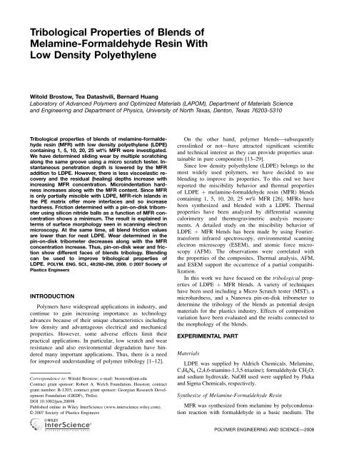
<strong>Tribological</strong> Properties <strong>of</strong> Blends <strong>of</strong><br />
Melamine-Formaldehyde Resin With<br />
Low Density Polyethylene<br />
Witold Brostow, Tea Datashvili, Bernard Huang<br />
Laboratory <strong>of</strong> Advanced Polymers and Optimized Materials (LAPOM), Department <strong>of</strong> Materials Science<br />
and Engineering and Department <strong>of</strong> Physics, University <strong>of</strong> North Texas, Denton, Texas 76203-5310<br />
<strong>Tribological</strong> <strong>properties</strong> <strong>of</strong> <strong>blends</strong> <strong>of</strong> <strong>melamine</strong>-formaldehyde<br />
resin (MFR) with low density polyethylene (LDPE)<br />
containing 1, 5, 10, 20, 25 wt% MFR were investigated.<br />
We have determined sliding wear by multiple scratching<br />
along the same groove using a micro scratch tester. Instantaneous<br />
penetration depth is lowered by the MFR<br />
addition to LDPE. However, there is less viscoelastic recovery<br />
and the residual (healing) depths increase with<br />
increasing MFR concentration. Microindentation hardness<br />
increases along with the MFR content. Since MFR<br />
is only partially miscible with LDPE, MFR-rich islands in<br />
the PE matrix <strong>of</strong>fer more interfaces and so increase<br />
hardness. Friction determined with a pin-on-disk tribometer<br />
using silicon nitride balls as a function <strong>of</strong> MFR concentration<br />
shows a minimum. The result is explained in<br />
terms <strong>of</strong> surface morphology seen in scanning electron<br />
microscopy. At the same time, all blend friction values<br />
are lower than for neat LDPE. Wear determined in the<br />
pin-on-disk tribometer decreases along with the MFR<br />
concentration increase. Thus, pin-on-disk wear and friction<br />
show different faces <strong>of</strong> <strong>blends</strong> tribology. Blending<br />
can be used to improve tribological <strong>properties</strong> <strong>of</strong><br />
LDPE. POLYM. ENG. SCI., 48:292–296, 2008. ª 2007 Society <strong>of</strong><br />
Plastics Engineers<br />
INTRODUCTION<br />
Polymers have widespread applications in industry, and<br />
continue to gain increasing importance as technology<br />
advances because <strong>of</strong> their unique characteristics including<br />
low density and advantageous electrical and mechanical<br />
<strong>properties</strong>. However, some adverse effects limit their<br />
practical applications. In particular, low scratch and wear<br />
resistance and also environmental degradation have hindered<br />
many important applications. Thus, there is a need<br />
for improved understanding <strong>of</strong> polymer tribology [1–12].<br />
Correspondence to: Witold Brostow; e-mail: brostow@unt.edu<br />
Contract grant sponsor: Robert A. Welch Foundation, Houston; contract<br />
grant number: B-1203; contract grant sponsor: Georgian Research Development<br />
Foundation (GRDF), Tbilisi.<br />
DOI 10.1002/pen.20898<br />
Published online in Wiley InterScience (www.interscience.wiley.com).<br />
On the other hand, polymer <strong>blends</strong>—subsequently<br />
crosslinked or not—have attracted significant scientific<br />
and technical interest as they can provide <strong>properties</strong> unattainable<br />
in pure components [13–29].<br />
Since low density polyethylene (LDPE) belongs to the<br />
most widely used polymers, we have decided to use<br />
blending to improve its <strong>properties</strong>. To this end we have<br />
reported the miscibility behavior and thermal <strong>properties</strong><br />
<strong>of</strong> LDPE þ <strong>melamine</strong>-formaldehyde resin (MFR) <strong>blends</strong><br />
containing 1, 5, 10, 20, 25 wt% MFR [26]. MFRs have<br />
been synthesized and blended with a LDPE. Thermal<br />
<strong>properties</strong> have been analyzed by differential scanning<br />
calorimetry and thermogravimetric analysis measurements.<br />
A detailed study on the miscibility behavior <strong>of</strong><br />
LDPE þ MFR <strong>blends</strong> has been made by using Fouriertransform<br />
infrared spectroscopy, environmental scanning<br />
electron microscopy (ESEM), and atomic force microscopy<br />
(AFM). The observations were correlated with<br />
the <strong>properties</strong> <strong>of</strong> the composites. Thermal analysis, AFM,<br />
and ESEM support the occurrence <strong>of</strong> a partial compatibilization.<br />
In this work we have focused on the tribological <strong>properties</strong><br />
<strong>of</strong> LDPE þ MFR <strong>blends</strong>. A variety <strong>of</strong> techniques<br />
have been used including a Micro Scratch tester (MST), a<br />
microhardness, and a Nanovea pin-on-disk tribometer to<br />
determine the tribology <strong>of</strong> the <strong>blends</strong> as potential design<br />
materials for the plastics industry. Effects <strong>of</strong> composition<br />
variation have been evaluated and the results connected to<br />
the morphology <strong>of</strong> the <strong>blends</strong>.<br />
EXPERIMENTAL PART<br />
Materials<br />
LDPE was supplied by Aldrich Chemicals. Melamine,<br />
C 3 H 6 N 6 (2,4,6-triamino-1,3,5-triazine); formaldehyde CH 2 O;<br />
and sodium hydroxide, NaOH used were supplied by Fluka<br />
and Sigma Chemicals, respectively.<br />
Synthesize <strong>of</strong> Melamine-Formaldehyde Resin<br />
MFR was synthesized from <strong>melamine</strong> by polycondensation<br />
reaction with formaldehyde in a basic medium. The<br />
VC 2007 Society <strong>of</strong> Plastics Engineers<br />
POLYMER ENGINEERING AND SCIENCE—-2008
molar ratio <strong>melamine</strong>/formaldehyde was between 1 and 3.<br />
pH <strong>of</strong> formaldehyde (37.0% by weight in water) was<br />
adjusted to 7.5–8.0 by adding 10 wt% NaOH aqueous solution.<br />
The resulting solution was placed in a beaker and thoroughly<br />
mixed with 20 g <strong>melamine</strong>; the components were<br />
then stirred for 40 min at 1208C. The resulting structure is<br />
the indentation was 5 s. Five indentations were made for<br />
each sample. The mean value <strong>of</strong> the Vickers microhardness<br />
as averaged from five different tests was obtained<br />
using the formula<br />
h v ¼ 1854:4 P d 2 ; (2)<br />
where P is the load in g while d is the mean diagonal <strong>of</strong><br />
indentation in mm.<br />
The final product was subjected to evaporation. To achieve<br />
complete water removal, the evaporation was carried out at<br />
708C and the residual pressure 13–16 kPa, followed by drying<br />
in an oven at 808C for 24 hr.<br />
Blending and Sample Preparation<br />
Blends <strong>of</strong> dried PE and MFR were prepared by melt<br />
mixing in a C.W. Brabender D - 52 Preparation Station at<br />
the rotation speed <strong>of</strong> 80 rpm and at 1608C. The resulting<br />
<strong>blends</strong> were pelletized and dried. The <strong>blends</strong> contained in<br />
turn 1, 5, 10, 20, and 25 wt% MFR.<br />
Subsequently, the <strong>blends</strong> were dried for 8 hr at 1008C<br />
before compressing them in a Carver compression molding<br />
machine at 1608C at the compression pressure 20.7 <br />
10 3 kPa.<br />
Sliding Wear Determination<br />
The first tribological test performed for each blend consisted<br />
using a Micro-Scratch Tester (MST) from CSEM,<br />
Neufchatel, Switzerland, utilizing the CSEM Scratch S<strong>of</strong>tware<br />
Version 2.3, which applies a constantly increasing<br />
force from 0 to 25.0 N to the samples, or else a constant<br />
force. Multiple scratching following the same groove provides<br />
us with sliding wear determination (SWD) results.<br />
For each sample 15 scratches were performed. The parameters<br />
used in the tests were the following: load 10.0 N,<br />
scratch length 5.0 mm, scratch velocity 5.0 mm/min at<br />
room temperature. A conical diamond intender with 200<br />
mm <strong>of</strong> diameter and the cone angle <strong>of</strong> 1208 was used. The<br />
results consist <strong>of</strong> the penetration (instantaneous) depth R p<br />
and the healing (recovery) depth R h determined 5 min later.<br />
Microhardness Measurements<br />
The Vickers microhardness h Vickers <strong>of</strong> each blend was<br />
determined with a dynamic microhardness measurement<br />
device, HMV-M Shimadzu Micro Hardness Tester; model<br />
M3, from Shimadzu, Kyoto, Japan.<br />
Loads <strong>of</strong> 100, 200, and 300 g were used to make<br />
microindentations. The holding time after completion <strong>of</strong><br />
(1)<br />
Friction and Wear Measurements<br />
Friction tests were conducted on the Nanoevea pin-ondisk<br />
tribometer from Micro Photonics. The tribometer provides<br />
simulation <strong>of</strong> friction and wear processes under sliding<br />
conditions. It can be operated for solid friction without<br />
lubrication and for boundary lubrication with liquid lubricants.<br />
Thus, both material <strong>properties</strong> and lubricant effects<br />
can be determined. A stationary test specimen, pin or ball,<br />
with a defined normal force is pressed against the surface <strong>of</strong><br />
another test specimen placed on the rotary disk. The normal<br />
force is applied over the pin or ball by means <strong>of</strong> a set <strong>of</strong><br />
dead weights between 0 and 60 N. This allows a stable force<br />
during the test. The pin, or ball, is mounted on a stiff arm,<br />
designed as a frictionless extensometer force transducer.<br />
The friction is determined from the friction force by<br />
means <strong>of</strong> the deflection <strong>of</strong> the elastic arm. Strain gauges<br />
bonded on the elastic body <strong>of</strong> the arm convert it into a force<br />
sensor and allow the direct measurement <strong>of</strong> the friction<br />
force. The rotation <strong>of</strong> the disk is driven by a servo motor,<br />
between 0 rpm and 500 rpm. Thus, except for very small<br />
rpm values, we are dealing with dynamic friction. Wear/<br />
depth measurement can be performed by measuring the<br />
changing angle <strong>of</strong> the arm during the test using an inductive<br />
displacement sensor. The geometrical relationship<br />
between the arm and support <strong>of</strong> the sensor provides a measure<br />
<strong>of</strong> wear. Silicon nitride ceramic balls (NBD200) made<br />
by Saint-Gobain Ceramics with the diameter 3.2 mm are<br />
used. Before each test, the surfaces <strong>of</strong> the samples were<br />
polished with metallographic abrasive paper. Then the ball<br />
was cleaned in acetone and thoroughly dried. Each test was<br />
performed under the following conditions: temperature (20<br />
6 2) 8C, speed 100 rpm, radius 2.0 mm, weight 5.0 N. The<br />
test durations ranged between 20 and 30 min.<br />
SLIDING WEAR RESULTS<br />
The viscoelastic recovery j has been defined [8] as<br />
R h<br />
j ¼ R p<br />
100%: (3)<br />
R h<br />
The definition is usable in single scratching [8] as well as<br />
in SWD tests [27].<br />
DOI 10.1002/pen POLYMER ENGINEERING AND SCIENCE—-2008 293
FIG. 1. Penetration depth <strong>of</strong> LDPE þ MFR <strong>blends</strong> at the constant force<br />
<strong>of</strong> 10.0 N.<br />
FIG. 3. Viscoelastic recovery <strong>of</strong> LDPE þ MFR <strong>blends</strong> calculated from<br />
Eq. 3 at the constant force <strong>of</strong> 10.0 N.<br />
In each SWD run made at a constant force we obtain a<br />
diagram <strong>of</strong> the depth as a function <strong>of</strong> the scratch number.<br />
In all runs the full range was 5.0 mm. For detailed analysis<br />
we have used the depth at 2.5 mm in the middle <strong>of</strong><br />
the scratching range.<br />
In Fig. 1 we show the penetration depth R p curves for<br />
constant load as a function <strong>of</strong> the number <strong>of</strong> scratch tests<br />
performed.<br />
The neat LDPE material was examined as a reference<br />
to compare the values with those for the <strong>blends</strong>. It is<br />
clearly seen in Fig. 1 that <strong>blends</strong> are more resistant to instantaneous<br />
deformation by microscratching. At 10.0 N<br />
force <strong>blends</strong> have the original penetration depths R p ranging<br />
from 200 to 250 mm while LDPE has R p 350 mm.<br />
In Fig. 2 we display the residual depth R h diagrams in<br />
the same way.<br />
We see in Fig. 2 that the situation is inverted for the<br />
residual depth R h . All <strong>blends</strong> have larger residual depth<br />
thanLDPE.BothFigs.1and2confirmforLDPEand<br />
its <strong>blends</strong> the phenomenon <strong>of</strong> strain hardening in sliding<br />
wear reported first in Ref. 27. The phenomenon can be<br />
explained by in terms <strong>of</strong> densification <strong>of</strong> the bottom and<br />
sides <strong>of</strong> the groove [30]. We also recall in this context<br />
a connection between nanoscratching and nanoindentation<br />
[31].<br />
In Fig. 3 we can see the values <strong>of</strong> viscoelastic recovery<br />
as defined by Eq. 2, also as a function <strong>of</strong> the number <strong>of</strong><br />
tests.<br />
We find that the viscoelastic recovery <strong>of</strong> <strong>blends</strong> is in<br />
the range between 65 and 80% while that <strong>of</strong> LDPE is<br />
between 80 and 85%. All three series <strong>of</strong> results can be<br />
explained by MFR providing increased crystallinity.<br />
Lower penetration depths result, but there is less recovery<br />
and thus higher residual depths.<br />
VICKERS MICROHARDNESS<br />
Microhardness values determined as described in Section<br />
2.2 and calculated from Eq. 1 are listed in Table 1.<br />
We have covered the range from 100 to 300 g in our<br />
experiments. Variations <strong>of</strong> the microhardness with the<br />
load applied are small; neglecting them constitutes a reasonable<br />
approximation. For consistency, we list in the<br />
Table values for the load <strong>of</strong> 200 g.<br />
Table 1 tells us that the microhardness values increase<br />
with increasing MFR concentration. As concluded in the<br />
previous article [26] there is a partial but not complete<br />
miscibility <strong>of</strong> the components. Thus, there exist MFR-rich<br />
islands in the predominantly PE matrix. Apparently interfacial<br />
boundaries <strong>of</strong>fer more resistance to microindentation<br />
than PE alone.<br />
TABLE 1.<br />
Material<br />
Vickers microhardness values <strong>of</strong> the different <strong>blends</strong>.<br />
Vickers microhardness h Vickers<br />
FIG. 2. Residual depth <strong>of</strong> LDPE þ MFR <strong>blends</strong> at the constant force<br />
<strong>of</strong> 10.0 N.<br />
LDPE 23.9<br />
99% LDPE 24.5<br />
95% LDPE 25.1<br />
90% LDPE 25.8<br />
80% LDPE 26.6<br />
75% LDPE 28.2<br />
294 POLYMER ENGINEERING AND SCIENCE—-2008 DOI 10.1002/pen
PIN-ON-DISK FRICTION<br />
Curves showing the variation <strong>of</strong> friction with the number<br />
<strong>of</strong> revolutions for LDPE þ MFR <strong>blends</strong> and for pure<br />
LDPE are shown in Fig. 4.<br />
We see in Fig. 4 that the friction <strong>of</strong> pure LDPE is<br />
higher than that <strong>of</strong> the <strong>blends</strong>. For <strong>blends</strong> the friction<br />
slowly increases in the initial stage <strong>of</strong> sliding, then in<br />
some cases decreases slightly, and eventually reaches a<br />
steady stage. For pure LDPE no decreasing period is seen,<br />
the friction only increases before reaching a steady stage.<br />
From the Nanoevea pin-on-disk tribometer measurements<br />
performed for the <strong>blends</strong>, the average friction and<br />
wear was determined over the whole range <strong>of</strong> cycles, as<br />
shown in Fig. 5.<br />
Figure 5 tells us that the friction as a function <strong>of</strong> composition<br />
exhibits a minimum around 10 wt% MFR. One<br />
possible explanation can be in terms <strong>of</strong> ‘‘bumps’’ on predominantly<br />
PE-rich surface. The bumps lower the friction<br />
as long as they are small. However, upon an increase <strong>of</strong><br />
MFR concentration above 10 wt%, the bumps apparently<br />
increase in their surface areas, thus increasing the friction<br />
again. Scanning electron microscopy results reported earlier<br />
[26] support this interpretation. However, even for 25<br />
wt% MFR the friction is still lower than for pure LDPE.<br />
The behavior <strong>of</strong> wear is different than that <strong>of</strong> friction:<br />
addition <strong>of</strong> MFR always results in lowering wear. In this<br />
respect wear behaves symbatically with the microindentation<br />
hardness, but not with friction. We infer that conclusions<br />
on wear cannot be based on friction results only.<br />
FIG. 5.<br />
(a, b) Average friction and wear <strong>of</strong> LDPE þ MFR <strong>blends</strong>.<br />
CONCLUSIVE REMARKS<br />
As expected the tribological <strong>properties</strong> <strong>of</strong> <strong>blends</strong> are<br />
related to their composition. The addition <strong>of</strong> the MFR to<br />
PE causes gradual decreases <strong>of</strong> both friction and wear,<br />
while the scratch resistance increases. As for mechanical<br />
<strong>properties</strong>, the higher the MFR content the higher the<br />
hardness <strong>of</strong> the blend. However, the viscoelastic recovery<br />
<strong>of</strong> <strong>blends</strong> is only 65–80% while that <strong>of</strong> LDPE is 80–90%.<br />
A possible explanation <strong>of</strong> this is that higher hardness<br />
FIG. 4.<br />
Friction <strong>of</strong> LDPE þ MFR <strong>blends</strong>.<br />
brought about by the MFR component hinders viscoelastic<br />
recovery.<br />
REFERENCES<br />
1. M. Watanabe and H. Yamaguchi, Wear, 110, 379 (1986).<br />
2. J.W.M. Mens and A.W.J. de Gee, Wear, 149, 255 (1991).<br />
3. J.H. Byett and C. Allen, Tribol. Int., 25, 237 (1992).<br />
4. Y. Laigui and S. Bahadur, Wear, 214, 245 (1998).<br />
5. S.N. Kukureka, C.J. Hooke, M. Rao, P. Liao and Y.K.<br />
Chen, Tribol. Int., 32, 107 (1999).<br />
6. Y.K. Chen, S.N. Kukureka, C.J. Hooke, and M. Rao, J.<br />
Mater. Sci., 35, 1269 (2000).<br />
7. W. Brostow, P.E. Cassidy, H.E. Hagg, M. Jaklewicz, and<br />
P.E. Montemartini, Polymer, 42, 7971 (2001).<br />
8. W. Brostow, B. Bujard, P.E. Cassidy, H.E. Hagg, and P.E.<br />
Montemartini, Mater. Res. Innovat., 6, 7 (2001).<br />
9. Y. Yamamoto and T. Takashima, Wear, 253, 820 (2002).<br />
10. W. Brostow, J.L. Deborde, M. Jaklewicz, and P. Olszynski,<br />
J. Mater. Ed., 24, 119 (2003).<br />
11. W. Brostow, J.A. Hinze, and R. Simoes, J. Mater. Res., 19,<br />
851 (2004).<br />
12. W. Brostow and R. Simoes, J. Mater. Ed., 27, 19 (2005).<br />
13. S. Akhtar and J.L. White, Polym. Eng. Sci., 32, 690 (1992).<br />
14. J. Hanchi and N.S. Eiss, Wear, 200, 105 (1996).<br />
DOI 10.1002/pen POLYMER ENGINEERING AND SCIENCE—-2008 295
15. W. Brostow, N.A. D’Souza, H. Galina, and A.C. Ramamurthy,<br />
Polym. Eng. Sci., 36, 1101 (1996).<br />
16. P. Christjanson, A. Köösel, K. Siimer, and A. Suurpere,<br />
Polym. Eng. Sci., 37, 928 (1997).<br />
17. R. Agarwal and J.P. Bell, Polym. Eng. Sci., 38, 299 (1998).<br />
18. J. Karger-Kocsis, Ed., Polypropylene: An A-Z Reference,<br />
Kluwer, Boston (1999).<br />
19. V. Kalkis, R.D. Maksimov, and J. Zicans, Polym. Eng. Sci.,<br />
39, 1365 (1999).<br />
20. J.C.M. Suarez, E.B. Mano, and C.M.C. Bonelli, Polym. Eng.<br />
Sci., 39, 1398 (1999).<br />
21. M. Kyotani and A. Saeed, Polym. Eng. Sci., 39, 1480<br />
(1999).<br />
22. O. Gryshchuk and J. Karger-Kocsis, J. Polym. Sci. Chem.,<br />
42, 5471 (2004).<br />
23. S. Jose, S. Thomas, E. Lievana, and J. Karger-Kocsis, J.<br />
Appl. Polym. Sci., 95, 1376 (2005).<br />
24. R. Palkovits, H. Althues, A. Rumplecker, B. Tesche, A.<br />
Dreier, U. Holle, G. Fink, C.H. Cheng, D.F. Shantz, and<br />
S. Kaskel, Langmuir, 21, 6048 (2005).<br />
25. N.J.W. Gamage, D.J.T. Hill, P.J. Pomery, and C.A. Lukey,<br />
Polym. Eng. Sci., 46, 532 (2006).<br />
26. W. Brostow and T. Datashvili, Mater. Res. Innovat., in<br />
press.<br />
27. W. Brostow, D. Darmarla, J. Howe, and D. Pietkiewicz,<br />
e-Polymers, 025, 1 (2004).<br />
28. W. Brostow, H.E. Hagg Lobland, and M. Narkis, J. Mater.<br />
Res., 21, 2422 (2006).<br />
29. W. Brostow, B.P. Gorman, and O. Olea-Mejia, Mater. Lett.,<br />
61, 1333 (2007).<br />
30. W. Brostow, W. Chonkaew, L. Rapoport, Y. Soifer, and A.<br />
Verdyan, J. Mater. Res., in press.<br />
31. K. Rau, R. Singh, and E. Goldberg, Mater. Res. Innovat., 5,<br />
151 (2002).<br />
296 POLYMER ENGINEERING AND SCIENCE—-2008 DOI 10.1002/pen