ThunderJet Instructions - Zipper's Performance Products
ThunderJet Instructions - Zipper's Performance Products
ThunderJet Instructions - Zipper's Performance Products

You also want an ePaper? Increase the reach of your titles
YUMPU automatically turns print PDFs into web optimized ePapers that Google loves.
S&S G/D In s ta l l at i o n a n d<br />
Tu n i n g In s t r u c t i o n s<br />
These products are legal for sale in the State of California only for<br />
racing vehicles which may never be used upon a highway.<br />
READ INSTRUCTIONS FIRST!<br />
AIR FILTER<br />
This is the first issue to<br />
talk about because when making<br />
changes here, it can change jetting<br />
requirements. The foam filter restricts<br />
airflow. We have found the best alternative<br />
is a high flow K&N filter. It will give you<br />
the performance you demand while doing<br />
a better job of filtering incoming air than<br />
a foam filter can. We stock these for all<br />
S&S applications and also manufacture<br />
alternative systems.<br />
WE STRONGLY RECOMMEND THIS!<br />
ACCELERATOR PUMP<br />
We recommend turning off<br />
the accelerator pump when tuning the<br />
intermediate circuit. It doesn’t supply fuel<br />
at steady speeds and can mask problems<br />
of a lean condition. This is evident with<br />
plug readings that look good or even<br />
rich and the next week you may have<br />
two burnt pistons. To disable the pump<br />
when tuning a high performance engine,<br />
turn the adjusting screw clockwise until it<br />
contacts the pump arm. CAUTION: DO<br />
NOT OVERTIGHTEN. When tuning is<br />
complete you can increase pump travel<br />
to aid cold starts. For best results, keep<br />
the volume low on this circuit. Clearance<br />
should be .020” to .030” @ adjustment<br />
screw<br />
OFF IDLE RESPONSE &<br />
LOW TO MID-RANGE POWER<br />
INTERMEDIATE (LOW SPEED) JET<br />
After years of development on<br />
S&S carburetors, we have noticed that<br />
this circuit is the most misunderstood<br />
in the overall picture of the fuel curve.<br />
When engine efficiency has been increased<br />
via improved airflow, compression, larger<br />
displacement, etc., the volume of fuel in this<br />
circuit must be raised. You increase fuel to<br />
increase power but also to prevent engine<br />
damage. With a wide variety of engine<br />
sizes, components and exhaust systems,<br />
we can only offer a broad recommendation<br />
of two sizes larger than stock setting,<br />
some engines will require substantially<br />
more. Call us for special jets if you need<br />
them. This is truly a hidden treasure.<br />
TUNE IT CORRECTLY!<br />
IDLE MIXTURE<br />
This is the next step after increasing<br />
the intermediate jet. Disregard the factory<br />
setting on this circuit. When you drastically<br />
increase the intermediate jet, this mixture will<br />
be rich. In some cases, we find the correct<br />
setting may be only 1/2 turn out from the seat.<br />
NOTE: Never richen this circuit to<br />
compensate for lean conditions on the<br />
intermediate circuit.<br />
MID-RANGE TUNING<br />
THE AIR BLEED<br />
The Air Bleed is an air passage<br />
connected to the Main Jet emulsion tube<br />
that allows air to mix with fuel before it is<br />
pulled into the carb throat. You may find<br />
now that you’ve increased the Low Speed<br />
jet size, the engine responds better off idle,<br />
but now has a stutter or hesitation (flat spot)<br />
as the rpm rises to a level that recognizes<br />
the carb’s Main Jet. With the stock sized<br />
(.042) Air Bleed, fuel starts being pulled<br />
through the Main Jet at a relatively low rpm,<br />
causing this rich condition. By increasing<br />
the Air Bleed size, you are in effect raising<br />
the rpm level needed to draw more fuel from<br />
the Main Jet. Simply, it allows for increased<br />
THE AIR BLEED CONT’D<br />
rpm before fuel is drawn from the Main<br />
Jet, in order to correct a rich fuel overlap<br />
from the Low Speed to Main Jet circuit<br />
transition.<br />
Now you can tune the Main<br />
Jet in at a higher rpm level, when the<br />
engine will want (and need) more fuel.<br />
This circuit can also help you manipulate<br />
problems you may be experiencing<br />
with certain hydraulic lifter camshafts,<br />
exhaust systems and other components.<br />
These components might not allow the<br />
engine to carburet very well in the middle<br />
of the scale. The air bleed allows you<br />
to remove some of the fuel volume when<br />
the requirement is low. Other circuits are<br />
used to compensate for any demand.<br />
Keep a good selection of these on hand<br />
to tune for best power<br />
MID-RANGE AND TOP END<br />
MAIN JET<br />
Now that you have a handle on<br />
the air bleed and intermediate circuits, you<br />
can use the main jet to increase the power<br />
in the mid-range and top-end. When<br />
you’re changing jets, keep in mind the<br />
relationship of the air bleed to the main jet.<br />
Chances are that if you had good<br />
power at peak rpm before you installed<br />
the <strong>ThunderJet</strong>, you will probably<br />
drop two sizes on the main jet after<br />
installation.<br />
Check chart for starting point.<br />
TOP END<br />
THUNDERJET<br />
This circuit is doing a lot of<br />
demand work. Because of its built in<br />
air bleed system, it becomes active at<br />
approximately 4000-4200 rpms, while<br />
the engine is under a controlled load.<br />
Use <strong>ThunderJet</strong> to tune (with the main<br />
jet) for maximum power increases at high<br />
rpm. If you are tuning on a dyno, make<br />
small jet changes to see the difference<br />
it makes. You will be surprised at the<br />
power increases.<br />
Jetting instructions continued on<br />
the back of this page!<br />
ThunderTech <strong>Products</strong> - 6655-A Amberton Drive - Elkridge, MD - 21075 - PH: (410)579-2929 - Fax: (410)579-2835
Tu n i n g In s t r u c t i o n s<br />
Co n t i n u e d f r o m Fr o n t Pa g e<br />
SUPER ‘G’ CARBS AND<br />
TODAY’S LARGER ENGINES<br />
We have found there is a need<br />
for enlarging the throat size in the Super<br />
‘G’ Carb in certain big inch applications.<br />
At mid-range rpm’s, air speed is simply<br />
to high at the nozzle, resulting in a big<br />
surge of fuel and its related stumble,<br />
or sooty looking plugs. Lowering the<br />
main jet size helps the problem but<br />
dangerously leans out the mixture for<br />
high rpm running (result-burnt pistons).<br />
Boring the carb throat will lower the air<br />
speed at the main discharge tube. This<br />
smoothes out the fuel curve and allows<br />
you to run adequate main jet sizes for<br />
these big engines. If you choose to do<br />
this modification yourself, be careful;<br />
there is very little room for error here.<br />
MANIFOLD SPACER BLOCKS<br />
When tuning a long stroke<br />
engine, increasing runner (manifold)<br />
length may help control fuel standoff<br />
and improve low- and mid-range<br />
carburetion. Different cams, exhausts,<br />
strokes and other changes will affect this<br />
area dramatically. If you are a serious<br />
tuner, we suggest you purchase spacers<br />
and insulator blocks and experiment with<br />
them in your applications.<br />
VACUUM PETCOCKS<br />
We recommend replacing<br />
any late model vacuum petcock<br />
with a Pingel High-Flow Petcock in<br />
performance applications.<br />
MOUNTING<br />
Tests on the Dyno and the track<br />
have shown properly mounted carbs work<br />
superior to units that move and shake due<br />
to inadequate mounting. Make sure the<br />
carb is properly and securely mounted.<br />
DON’T OVERLOOK THIS AREA!<br />
REMEMBER...<br />
Check mixture after any Low<br />
Speed jet change. At maximum rpm, all<br />
three circuits are supplying fuel. If you<br />
add fuel to one circuit, you may have to<br />
take away from another as you have now<br />
enriched the entire mixture throughout.<br />
Re m e m b e r:<br />
Tu n i n g Is Ev e ry t h i n g!<br />
Use of This Product is<br />
Intended for Racing<br />
Purposes Only.<br />
Re p l a c e m e n t Pa r t s & Se r v i c e s<br />
• <strong>ThunderJet</strong> kits and jets sizes<br />
80-200<br />
• Special S&S jets--air bleed jets<br />
• Spacers and Insulator blocks<br />
• Velocity stacks (racing only)<br />
• High flow air filters<br />
• Replacement parts and<br />
mounting hardware<br />
• Complete application-specific<br />
carbs with <strong>ThunderJet</strong>s<br />
• Professional installation for<br />
these parts<br />
• Special application carbs<br />
• Installation Fixtures<br />
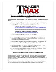
Je t t i n g Ra n g e Gu i d e Fo r Th u n d e rJe t Tu n i n g<br />
No t e : The suggested starting points are based at sea level. When looking at<br />
the scale, consider that cam, compression, head flow and especially exhaust<br />
type can greatly affect each circuit. Open exhaust systems such as drag pipes<br />
will rely heavily on the <strong>ThunderJet</strong> circuit and less on the main jet for mid-range<br />
to high RPM power; tune accordingly. <strong>Performance</strong> systems will generally tune<br />
to the middle of the suggested jet range. Install baseline jetting and tune from<br />
there. Refer to circuit instructions above for help with fine tuning specific RPM<br />
ranges. Each engine has different requirements; time spent tuning will yield the<br />
best results.<br />
UNDERJET<br />
ThunderTech <strong>Products</strong> - 6655-A Amberton Drive - Elkridge, MD - 21075 - PH: (410)579-2929 - Fax: (410)579-2835
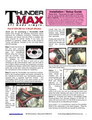
Fo r S&S ‘G’<br />
Ca r b u r e t o r s<br />
READ GENERAL INSTRUCTIONS FIRST!<br />
If you do not have facilities available<br />
to properly install this module,<br />
professional installation is available<br />
from Zipper’s. High volume shops<br />
may want to invest in our <strong>ThunderJet</strong><br />
installation fixture (shown in the<br />
photos, p/n 713-910).<br />
This securely holds the Carb body<br />
and float bowl at the correct positions<br />
for machining. For use with a mill<br />
when installing <strong>ThunderJet</strong>s in all<br />
S&S model E/G/B/D carbs.<br />
Please read all instructions<br />
fully and carefully before<br />
proceeding.<br />
1. Loosen the drain nut and remove<br />
your float bowl from the Carb.<br />
Remove emulsion tube with main<br />
jet from Carb body and remove the<br />
accelerator pump rod, rubber bellows<br />
and discharge o-ring. Looking into<br />
Carb throat, turn Carb counterclockwise<br />
at approximately an 11<br />
degree angle and clamp in vice.<br />
Drilled, tapped and spot faced for<br />
fuel delivery tube.<br />
2. The location for drilling, tapping<br />
and spot facing the fuel tube hole is<br />
.950” from the air cleaner mounting<br />
surface; use the upper left corner of<br />
the “T” in the word “SHORTY” for<br />
locating the other axis. Drill a letter “I”<br />
hole, tap 5/16-24. Using 1/2” end mill,<br />
counterbore hole until you maintain a<br />
3/16” (.187) wall thickness (photo 1).<br />
3. Install the fuel delivery tube<br />
from the inside of the Carb throat<br />
out (photo 2). Using (2) ¼”-28 jam<br />
nuts, double-nut the fuel delivery<br />
tube outside of the Carb throat and<br />
carefully lock tube into Carb throat<br />
until all or most of the air bleed<br />
segment is exposed.<br />
Fuel delivery tube installed.<br />
3. Remove jam nuts (no longer<br />
needed). Install the air correction<br />
spacer (small opening out), o-ring and<br />
<strong>ThunderJet</strong> body on to Carb. Fuel line<br />
nipple should point to front of bike and<br />
slightly toward the air filter for hose<br />
routing (photo 3). Trim small opening<br />
side of air correction spacer, if needed,<br />
to achieve a hand tight location 1/6 of a<br />
turn from permanent location and finish<br />
tightening with wrench. (.006” trim =<br />
1/6 turn). DO NOT OVERTIGHTEN<br />
BODY OR FUEL TUBE BREAKAGE<br />
WILL RESULT!!<br />
Body and the air correction spacer<br />
installed, nipple facing front of<br />
bike.<br />
Do n o t o v e r t i g h t e n b o d y<br />
o r f u e l t u b e b r e a k a g e<br />
w i l l r e s u lt!<br />
Adjustable Air Bleed<br />
4. Locate air bleed passage plug<br />
above S&S nameplate on throttle<br />
spool side of Carb. Clamp Carb body<br />
at approximately a 45 degree angle.<br />
Center a 5/16” end mill over the plug<br />
and spot face lightly to flatten and<br />
align. Use a center drill to start and<br />
then drill the plug with a #19 drill bit and<br />
tap 5mm x .8mm for air bleed (photo<br />
4). Install air bleed jet (same type jet<br />
used in <strong>ThunderJet</strong>). Jet sizes range<br />
from 130-170 for most applications<br />
(see chart).<br />
Drilled, tapped, spot faced for<br />
adjustable air bleed jet.<br />
Original Air Bleed Blocking<br />
5. Clamp Carb in vise upside down.<br />
Locate original internal air bleed hole<br />
(photo 5) to be blocked off. (’04 and<br />
earlier) Carefully drill this passage with<br />
a #21 (.159”) drill bit until you break<br />
into cross passage in Carb body. Tap<br />
hole with a 10-32 tap, blow passage<br />
out with compressed air, then plug with<br />
supplied 10-32 slotted screw. (’05 and<br />
later) These carbs come with a main<br />
jet style air bleed jet; remove the jet<br />
and plug the hole with the supplied<br />
5/16-24 set screw.<br />
Original air bleed passage tapped<br />
for block-off screw.<br />
(Optional) Bowl Vent<br />
Relocation<br />
6. We have found additional<br />
performance and increased fuel<br />
pressure stability in the float bowl by<br />
relocating and modifying the float<br />
bowl vent passage. Clamp body<br />
upside down at a 45 degree angle.<br />
Remove the existing 5/16” bowl vent<br />
plug (photo 6). Using a small center<br />
drill or wiggler, locate the center of the<br />
hole where plug was removed. Mark<br />
a spot 7/16” from the casting surface<br />
where vent plug was removed, toward<br />
top of Carb. Using a small center<br />
drill, break through to existing vent<br />
passage. Finish hole using a 5/16”<br />
2-flute end mill at this angle. Cut only<br />
deep enough to enter existing vent<br />
cross drill!<br />
External bowl vent machined in<br />
body.<br />
In extreme high velocity applications,<br />
we recommend plugging the original<br />
vent passage at the air cleaner backing<br />
plate surface (tap opening 5/16-24).<br />
Use the 5/16”-24 plug removed from<br />
the vent passage to plug the original<br />
opening, as extreme airflow can create<br />
a vacuum that may draw fuel through<br />
the vent and uncontrollably richen<br />
the mixture. Install the plug just deep<br />
enough to be slightly below the air filter<br />
mounting surface, and use Loctite. If<br />
you choose not to do this modification,<br />
at least remove the vent plug and<br />
discard it.<br />
Remove bowl vent passage<br />
plug.<br />
Float Bowl<br />
7. Remove float from bowl. Set bowl<br />
at a 20 degree angle on sine plate.<br />
Drill a #3 hole between bowl drain plug<br />
and accelerator pump housing and tap<br />
with ¼”-28 tap. Spot face hole center<br />
(kiss) just enough to give a flat surface<br />
for o-ring to seal against (photo 8).<br />
Install fuel nipple and o-ring, secure<br />
inside bowl with lock washer and nut<br />
provided (photo 9). Make sure this<br />
device does not interfere with float<br />
action.<br />
Bowl drilled, tapped and spot<br />
faced for bowl fitting<br />
8. Thoroughly clean Carb, check low<br />
speed and main jet sizes for engine<br />
compatibility (see tuning tips), reassemble<br />
Carb and install fuel line with<br />
clamps provided. Fuel hose is routed<br />
to front of bike. See tuning instruction<br />
page for jetting instructions.<br />
Bowl fitting installed<br />
9. READ TUNING<br />
INSTRUCTIONS<br />
ThunderTech <strong>Products</strong> - 6655-A Amberton Drive - Elkridge, MD - 21075 - PH: (410)579-2929 - Fax: (410)579-2835
Fo r S&S ‘D’<br />
Ca r b u r e t o r s<br />
GENERAL INSTRUCTIONS<br />
If you do not have the facilities to properly<br />
install this fuel module, professional<br />
installation is available from Zipper’s.<br />
High volume shops may want to invest in<br />
our <strong>ThunderJet</strong> installation fixture (shown<br />
in the photos p/n 713-910) which securely<br />
holds the carb body and float bowl at the<br />
correct positions for machining. Use with a<br />
mill when installing <strong>ThunderJet</strong>s in all S&S<br />
model E/G/B/D carbs. Read all instructions<br />
fully and carefully before proceeding any<br />
further.<br />
Loosen drain plug and remove float bowl<br />
and manifold. Install two (2) studs in carb<br />
manifold bosses; use these to center<br />
carb in milling machine vise. Be careful<br />
not to over tighten carb in vise. The first<br />
two steps are recommended to further<br />
enhance your carb’s performance along<br />
with the installation of your <strong>ThunderJet</strong>.<br />
EXTERNAL FLOAT BOWL VENT<br />
1. Pressure in the float bowl is stabilized<br />
with the addition of this external bowl vent.<br />
Locate the new vent hole in the rear of the<br />
carb wall .438” above bowl gasket surface<br />
and 1.906” from the manifold flange of the<br />
carb. Open hole with a small center drill<br />
then plunge a 5/16” end mill to a depth of<br />
.562” below the raised surface. Use a ½”<br />
countersink to chamfer the raised surface<br />
to help start the tapping process. Chamfer<br />
only slightly not touching the lower level<br />
surface. Tap with 1/8” NPT tap. Install<br />
1/8” NPT street elbow and 1/8” NPT x 3/8”<br />
hose nipple using a suitable thread sealer.<br />
The hose nipple should be positioned<br />
pointing up.<br />
Tapping bowl vent for fitting<br />
ADJUSTABLE AIR BLEED<br />
CIRCUIT<br />
2. Earlier versions of “D” carbs are<br />
manufactured with a fixed size air bleed<br />
passage (current “D” models are now<br />
machined for adjustable air bleed jets).<br />
This modification will allow the tuner to<br />
adjust the main jet air bleed size for more<br />
control over the main jet circuit signal<br />
timing and fuel volume. Locate the fixed<br />
air bleed hole and bore with ¼” drill until<br />
you reach the cross drill in carb (DO NOT<br />
GO PAST CROSS DRILL!!). Spot face the<br />
area with 1/2” end mill for mating surface<br />
of jet. Use 5/16-24 starter tap in hole and<br />
remove to use a 5/16” bottom tap to finish<br />
job. Original air bleed size is .042” and the<br />
suggested range is .054-.072”. Use S&S<br />
main jets for this.<br />
Air bleed passage drilled & tapped<br />
for jet.<br />
THUNDERJET INSTALLATION<br />
NOTE: On “D” applications using only (1)<br />
<strong>ThunderJet</strong>, the <strong>ThunderJet</strong> mounts on the<br />
side of the carb facing the rear of the bike<br />
(9:00 position). If using (2) <strong>ThunderJet</strong>s follow<br />
all instructions below and mount one<br />
each in the 9:00 and 3:00 positions.<br />
9:00 POSITION<br />
3. Drill and tap hole .750” from the end<br />
of the carb throat, offset slightly above the<br />
throttle butterfly shaft. Use a letter ‘i’ (.272”)<br />
drill and tap 5/16”-24 thread. You will be<br />
drilling through the middle of the original<br />
float bowl vent passage; this is OK, it will not<br />
affect performance or operation of the carb.<br />
4. You then need to relieve the area<br />
around the hole you just threaded for<br />
air bleed spacer clearance. This is best<br />
accomplished on a vertical mill with a 3/4”<br />
end mill. With the cutter starting near the<br />
bowl area, mill toward the top of the carb,<br />
removing material at least ¼” above the<br />
centerline of the fuel tube hole. Use care<br />
not to break into the enrichener air passage<br />
located above the hole. Leave .170-.185” of<br />
carb wall for the short threaded portion of<br />
the fuel delivery tube.<br />
Fuel tube hole drilled/tapped, area<br />
relieved for <strong>ThunderJet</strong><br />
5.Install the fuel delivery tube from the<br />
inside of the carburetor throat out. Double<br />
nut the delivery tube using (2) ¼”-28 jam<br />
nuts and carefully lock into carb throat<br />
(DO NOT OVERTIGHTEN). Remove jam<br />
nuts (not needed after this step).<br />
6. Install air correction spacer, o-ring, and<br />
<strong>ThunderJet</strong> with fuel nipple facing down<br />
towards float bowl. Trim small opening<br />
Double-nut and tighten fuel tube<br />
in place<br />
side of air correction spacer, if needed,<br />
to achieve a hand tight location 1/6 of a<br />
turn from permanent location and finish<br />
tightening with wrench. (.006” trim = 1/6<br />
turn).<br />
ThunderTech <strong>Products</strong> - 6655-A Amberton Drive - Elkridge, MD - 21075 - PH: (410)579-2929 - Fax: (410)579-2835<br />
A.<br />
Do n o t o v e r t i g h t e n b o d y<br />
o r f u e l t u b e b r e a k a g e w i l l<br />
r e s u lt!<br />
<strong>ThunderJet</strong> body (nipple down),<br />
bowl cent & air bleed jet in place.<br />
3:00 POSITION<br />
(Part 2 of twin T-Jet installation)<br />
7. Drill and tap hole .950” from the end<br />
of the carb throat, offset slightly above the<br />
throttle butterfly shaft (letter ‘i’ (.272”) drill<br />
and 5/16”-24 tap).<br />
8. You then need to relieve the area around<br />
the hole you just threaded for air bleed spacer<br />
clearance. This is best accomplished on a<br />
vertical mill with a 3/4” end mill, on center<br />
of your threaded hole. Be certain to leave<br />
.170-.185” of carb wall for the short threaded<br />
portion of the fuel delivery tube. (Some D<br />
carbs are equipped with dual float bowl vent<br />
passages (forward and rear of carb throat);<br />
you will be cutting through the forward vent<br />
passage if equipped. This passage must<br />
then be plugged, as its location will subject<br />
the passage to positive air pressure at<br />
speed, resulting in fluctuating pressure in<br />
the float bowl, adversely affecting jetting.<br />
Drill the passage past the <strong>ThunderJet</strong><br />
mounting area and tap it 5/16”, 3/8” deep<br />
and plug it with a set screw. The external<br />
vent described in step 1 must be performed<br />
to replace this original vent.)<br />
fuel tube hole drilled/tapped,<br />
area relieved for T-Jet, fuel tube<br />
installed. Circle shows where vent<br />
passage should be plugged<br />
9. Follow steps 5, 6 & 7 from the 9:00<br />
segment.<br />
PRO-STOCK OPTION<br />
(12 O’Clock Position)<br />
If a third <strong>ThunderJet</strong> is desired, drill, tap<br />
(letter ‘i’ (.272”) drill and 5/16”-24 tap) and<br />
spot face TOP center of carb 1.200” from air<br />
cleaner backing plate surface, leaving .170-<br />
.185” wall thickness for the short threaded<br />
portion of the fuel delivery tube. Follow<br />
steps 5, 6 & 7 from the 9:00 segment. Point<br />
hose nipple towards rear of the bike and<br />
slightly inward.<br />
Spot faced, drilled/tapped for 3rd<br />
T-Jet (Pro-Stock option)<br />
FOAT BOWL<br />
10. Clamp bowl to mill table at 35 degree<br />
angle. See photo for bowl nipple location(s).<br />
At the bottom of float bowl, beside drain,<br />
drill a #3 hole and tap ¼”-28. Spot face the<br />
area around the hole to give a flat surface<br />
for the o-ring to seal against and reduce<br />
thickness enough to allow the nut to attach<br />
on the inside of the bowl. Install fuel nipple<br />
and o-ring then secure inside bowl with nut<br />
provided (no washer). Stake threads with a<br />
punch to lock nut in place (make sure this<br />
device does not interfere with float action or<br />
movement). Repeat for multiple bowl nipple<br />
locations.<br />
Hole A (9:00 position), B (3:00),<br />
C (12:00)<br />
12. Clean all carb parts; reassemble<br />
and install fuel line with clamps provided<br />
(trim fuel line if needed). Install on engine.<br />
Install fuel line, turn fuel valve on and check<br />
for leaks before starting engine!!<br />
13. READ TUNING<br />
INSTRUCTIONS