Bicycle Owners Manual - Felt Bicycles
Bicycle Owners Manual - Felt Bicycles
Bicycle Owners Manual - Felt Bicycles

You also want an ePaper? Increase the reach of your titles
YUMPU automatically turns print PDFs into web optimized ePapers that Google loves.
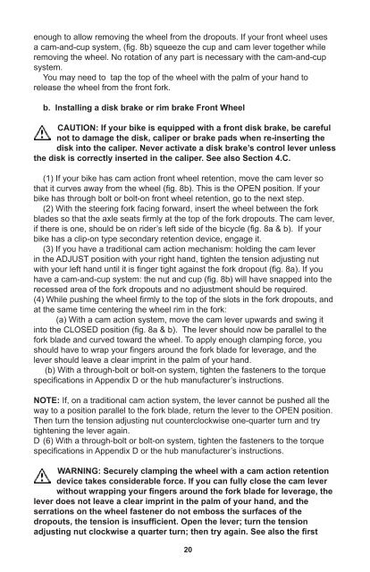
enough to allow removing the wheel from the dropouts. If your front wheel uses<br />
a cam-and-cup system, (fig. 8b) squeeze the cup and cam lever together while<br />
removing the wheel. No rotation of any part is necessary with the cam-and-cup<br />
system.<br />
You may need to tap the top of the wheel with the palm of your hand to<br />
release the wheel from the front fork.<br />
b. Installing a disk brake or rim brake Front Wheel<br />
CAUTION: If your bike is equipped with a front disk brake, be careful<br />
not to damage the disk, caliper or brake pads when re-inserting the<br />
disk into the caliper. Never activate a disk brake’s control lever unless<br />
the disk is correctly inserted in the caliper. See also Section 4.C.<br />
(1) If your bike has cam action front wheel retention, move the cam lever so<br />
that it curves away from the wheel (fig. 8b). This is the OPEN position. If your<br />
bike has through bolt or bolt-on front wheel retention, go to the next step.<br />
(2) With the steering fork facing forward, insert the wheel between the fork<br />
blades so that the axle seats firmly at the top of the fork dropouts. The cam lever,<br />
if there is one, should be on rider’s left side of the bicycle (fig. 8a & b). If your<br />
bike has a clip-on type secondary retention device, engage it.<br />
(3) If you have a traditional cam action mechanism: holding the cam lever<br />
in the ADJUST position with your right hand, tighten the tension adjusting nut<br />
with your left hand until it is finger tight against the fork dropout (fig. 8a). If you<br />
have a cam-and-cup system: the nut and cup (fig. 8b) will have snapped into the<br />
recessed area of the fork dropouts and no adjustment should be required.<br />
(4) While pushing the wheel firmly to the top of the slots in the fork dropouts, and<br />
at the same time centering the wheel rim in the fork:<br />
(a) With a cam action system, move the cam lever upwards and swing it<br />
into the CLOSED position (fig. 8a & b). The lever should now be parallel to the<br />
fork blade and curved toward the wheel. To apply enough clamping force, you<br />
should have to wrap your fingers around the fork blade for leverage, and the<br />
lever should leave a clear imprint in the palm of your hand.<br />
(b) With a through-bolt or bolt-on system, tighten the fasteners to the torque<br />
specifications in Appendix D or the hub manufacturer’s instructions.<br />
NOTE: If, on a traditional cam action system, the lever cannot be pushed all the<br />
way to a position parallel to the fork blade, return the lever to the OPEN position.<br />
Then turn the tension adjusting nut counterclockwise one-quarter turn and try<br />
tightening the lever again.<br />
D (6) With a through-bolt or bolt-on system, tighten the fasteners to the torque<br />
specifications in Appendix D or the hub manufacturer’s instructions.<br />
WARNING: Securely clamping the wheel with a cam action retention<br />
device takes considerable force. If you can fully close the cam lever<br />
without wrapping your fingers around the fork blade for leverage, the<br />
lever does not leave a clear imprint in the palm of your hand, and the<br />
serrations on the wheel fastener do not emboss the surfaces of the<br />
dropouts, the tension is insufficient. Open the lever; turn the tension<br />
adjusting nut clockwise a quarter turn; then try again. See also the first<br />
WARNING in this Section, p. 18.<br />
(6) If you disengaged the brake quick-release mechanism in 3. a. (1) above,<br />
re-engage it to restore correct brake pad-to-rim clearance.<br />
(7) Spin the wheel to make sure that it is centered in the frame and clears the<br />
brake pads; then squeeze the brake lever and make sure that the brakes are<br />
operating correctly.<br />
c. Removing a disk brake or rim brake Rear Wheel<br />
(1) If you have a multi-speed bike with a derailleur gear system: shift the rear<br />
derailleur to high gear (the smallest, outermost rear sprocket).<br />
If you have an internal gear rear hub, consult your dealer or the hub<br />
manufacturer’s instructions before attempting to remove the rear wheel.<br />
If you have a single-speed bike with rim or disk brake, go to step (4) below.<br />
(2) If your bike has rim brakes, disengage the brake’s quick-release<br />
mechanism to increase the clearance between the wheel rim and the brake pads<br />
(see Section 4.C, figs. 11 through 15).<br />
(3) On a derailleur gear system, pull the derailleur body back with your right<br />
hand.<br />
(4) With a cam action mechanism, move the quick-release lever to the<br />
OPEN position (fig. 8b). With a through bolt or bolt on mechanism, loosen the<br />
fastener(s) with an appropriate wrench, lock lever or integral lever; then push the<br />
wheel forward far enough to be able to remove the chain from the rear sprocket.<br />
(5) Lift the rear wheel off the ground a few inches and remove it from the rear<br />
dropouts.<br />
d. Installing a disk brake or rim brake Rear Wheel<br />
CAUTION: If your bike is equipped with a rear disk brake, be careful<br />
not to damage the disk, caliper or brake pads when re-inserting the<br />
disk into the caliper. Never activate a disk brake’s control lever unless<br />
the disk is correctly inserted in the caliper.<br />
(1) With a cam action system, move the cam lever to the OPEN position (see<br />
fig. 8 a & b). The lever should be on the side of the wheel opposite the derailleur<br />
and freewheel sprockets.<br />
(2) On a derailleur bike, make sure that the rear derailleur is still in its<br />
outermost, high gear, position; then pull the derailleur body back with your right<br />
hand. Put the chain on top of the smallest freewheel sprocket.<br />
(3) On single-speed, remove the chain from the front sprocket, so that you<br />
have plenty of slack in the chain. Put the chain on the rear wheel sprocket.<br />
(4) Then, insert the wheel into the frame dropouts and pull it all the way in to<br />
the dropouts.<br />
(5) On a single speed or an internal gear hub, replace the chain on the<br />
chainring; pull the wheel back in the dropouts so that it is straight in the frame<br />
and the chain has about 1/4 inches of up-and-down play.<br />
(6) With a cam action system, move the cam lever upwards and swing it into<br />
the CLOSED position (fig. 8 a & b). The lever should now be parallel to the seat<br />
stay or chain stay and curved toward the wheel. To apply enough clamping force,<br />
you should have to wrap your fingers around the fork blade for leverage, and the<br />
20 21