Vivotek IP8152-f4 Installation Guide - Use-IP
Vivotek IP8152-f4 Installation Guide - Use-IP
Vivotek IP8152-f4 Installation Guide - Use-IP

You also want an ePaper? Increase the reach of your titles
YUMPU automatically turns print PDFs into web optimized ePapers that Google loves.
510000221G<br />
Warning Before <strong>Installation</strong><br />
Power off the Network Camera as<br />
soon as smoke or unusual odors are<br />
detected.<br />
Do not place the Network Camera<br />
around heat sources, such as a<br />
television or oven.<br />
Keep the Network Camera away from<br />
direct sunlight.<br />
Do not place the Network Camera on<br />
unsteady surfaces.<br />
Do not disassemble the Network<br />
Camera.<br />
Keep the Network Camera away<br />
from water. If the Network Camera<br />
becomes wet, power off immediately.<br />
Refer to your user's manual for the<br />
operating temperature.<br />
Do not place the Network Camera in<br />
high humidity environments.<br />
Do not touch the Network Camera<br />
during a lightning storm.<br />
Do not drop the Network Camera.<br />
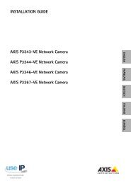
1 Package Contents<br />
<strong><strong>IP</strong>8152</strong><br />
CS-mount Lens<br />
Quick <strong>Installation</strong> <strong>Guide</strong><br />
Camera Stand<br />
Software CD<br />
Warranty Card<br />
L-type Hex Key Wrench<br />
Screws
2 Physical Description<br />
Front Panel<br />
Status LED<br />
Lens<br />
MicroSD/<br />
SDHC/<br />
SDXC<br />
Card Slot<br />
Rear Panel<br />
Mount ring<br />
adjustment<br />
Iris Control Cable Socket<br />
Mounting Hole<br />
Ethernet 10/100<br />
RJ45 Socket<br />
Recessed Reset Button<br />
1 2 3 4 5 6 7<br />
GND<br />
RS485_N<br />
DI<br />
GND_AUDIO<br />
RS485_P<br />
MIC_IN<br />
AUDIO_OUT<br />
General I/O Terminal<br />
Block<br />
Lens<br />
Focus Controller<br />
Zoom Controller<br />
EN - 2
English<br />
3 Mounting the Lens to the Camera<br />
1. Mount the lens by turning it clockwise onto the camera mount until it stops.<br />
2. Connect the iris control cable to the socket. Connect the iris control cable before<br />
power-on. Otherwise, you will not be able to access the exposure related<br />
settings.<br />
1<br />
2<br />
4 Mounting the Camera to Stand<br />
1. <strong>Use</strong> the holes on the camera stand to mark drill holes on the wall. Drill holes on your<br />
preferred location.<br />
2. Hammer in the included plastic anchors.<br />
3. Install the camera stand to wall or ceiling<br />
by driving screws through it.<br />
4. Attach the camera to stand by turning<br />
the stand and the fastening rings.<br />
EN - 3
POWER CO LISION<br />
1 2 3 4 5<br />
LINK<br />
RECEIVE<br />
PARTITION<br />
POWER COLLISION<br />
1 2 3 4 5<br />
LINK<br />
RECEIVE<br />
PARTITION<br />
5 Network Deployment<br />
Power over Ethernet (PoE)<br />
When using a PoE-enabled switch<br />
The Network Camera is PoE-compliant, allowing transmission of power and data via<br />
a single Ethernet cable. Follow the below illustration to connect the Network Camera<br />
to a PoE-enabled switch via Ethernet cable.<br />
PoE Switch<br />
When using a non-PoE switch<br />
<strong>Use</strong> a PoE power injector (optional) to connect between the Network Camera and a<br />
non-PoE switch.<br />
PoE Power Injector<br />
(optional)<br />
Non-PoE Switch<br />
EN - 4
English<br />
6 Assigning an <strong>IP</strong> Address<br />
1. Install "<strong>Installation</strong> Wizard 2" from the Software Utility directory on the software CD.<br />
2. The program will conduct an analysis of your network environment. After your network<br />
is analyzed, please click on the "Next" button to continue the program.<br />
3. The program will search for VIVOTEK Video Receivers, Video Servers, and Network<br />
Cameras on the same LAN.<br />
4. After a brief search, the main installer window will pop up. Double-click on the MAC<br />
address that matches the one printed on the camera label or the S/N number on the<br />
package box label to open a browser management session with the Network Camera.<br />
7<br />
Ready to <strong>Use</strong><br />
1. A browser session with the Network Camera should prompt as shown below.<br />
2. You should be able to see live video from your camera. You may also install the<br />
32-channel recording software from the software CD in a deployment consisting of<br />
multiple cameras. For its installation details, please refer to its related documents.<br />
For further setup, please refer to the user’s manual on the software CD.<br />
EN - 5
3. Unscrew the zoom controller to adjust the zoom factor. Upon completion, tighten the<br />
zoom controller.<br />
4. Unscrew the focus controller to adjust the focus range. Upon completion, tighten the<br />
focus controller.<br />
4<br />
3<br />
W<br />
N<br />
∞<br />
T<br />
NOTE:<br />
If you prefer other lens for your <strong><strong>IP</strong>8152</strong>, please notice the specifications below.<br />
1. If you select a different lens, the distance between the flange of the lens and the IR<br />
cut filter on the camera should be smaller than 7.5mm. If the lens protrudes too much<br />
from the bottom of the lens module, it may hit the IR Cut Filter, or result in out of focus<br />
when adjusting the focus controller.<br />
2. A vari-focal lens may protrude from the bottom of screw mount when tuning the focus<br />
puller.<br />
IR Cut<br />
Filter<br />
Lens<br />
protrudes from<br />
the screw<br />
mount<br />
Screw mount<br />
mm<br />
3. <strong>Use</strong> the included hex wrench to make adjustments to CS-mount ring only when you<br />
experience compatibility issue with lens focal length.<br />
EN - 6