datasheet: pdf - Octopart
datasheet: pdf - Octopart
datasheet: pdf - Octopart

Create successful ePaper yourself
Turn your PDF publications into a flip-book with our unique Google optimized e-Paper software.
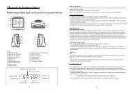
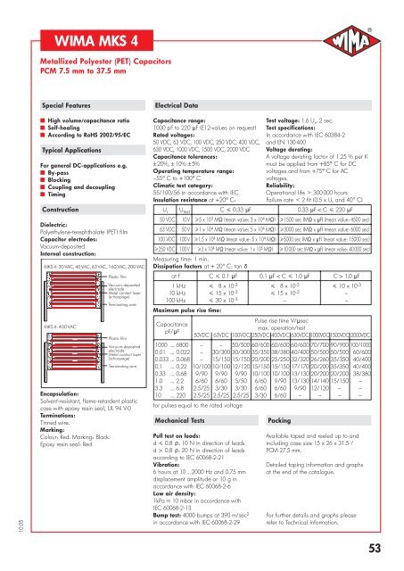
WIMA MKS 4<br />
D<br />
Metallized Polyester (PET) Capacitors<br />
PCM 7.5 mm to 37.5 mm<br />
Special Features<br />
Electrical Data<br />
10.05<br />
˜ High volume/capacitance ratio<br />
˜ Self-healing<br />
˜ According to RoHS 2002/95/EC<br />
Typical Applications<br />
For general DC-applications e.g.<br />
˜ By-pass<br />
˜ Blocking<br />
˜ Coupling and decoupling<br />
˜ Timing<br />
Construction<br />
Dielectric:<br />
Polyethylene-terephthalate (PET) film<br />
Capacitor electrodes:<br />
Vacuum-deposited<br />
Internal construction:<br />
MKS4:30VAC,40VAC,63VAC,160VAC,200VAC<br />
MKS 4: 400 VAC<br />
Plastic film<br />
Vacuum-deposited<br />
electrode<br />
Metal contact layer<br />
(schoopage)<br />
Terminating wire<br />
Plastic film<br />
Vacuum-deposited<br />
electrode<br />
Metal contact layer<br />
(schoopage)<br />
Terminating wire<br />
Encapsulation:<br />
Solvent-resistant, flame-retardent plastic<br />
case with epoxy resin seal, UL 94 V-0<br />
Terminations:<br />
Tinned wire.<br />
Marking:<br />
Colour: Red. Marking: Black.<br />
Epoxy resin seal: Red<br />
Capacitance range:<br />
1000 pF to 220 mF (E12-values on request)<br />
Rated voltages:<br />
50 VDC, 63 VDC, 100 VDC, 250 VDC, 400 VDC,<br />
630 VDC, 1000 VDC, 1500 VDC, 2000 VDC<br />
Capacitance tolerances:<br />
± 20%, ± 10% ± 5%<br />
Operating temperature range:<br />
–55+ C to +100+ C<br />
Climatic test category:<br />
55/100/56 in accordance with IEC<br />
Insulation resistance at +20+ C:<br />
U r U test C 0.33 mF 0.33 mF < C 220 mF<br />
50 VDC 10 V 5 x 10 3 M¸ (mean value: 3 x 10 4 M¸) 1500 sec (M¸ x mF) (mean value: 4500 sec)<br />
63 VDC 50 V 1 x 10 4 M¸ (mean value: 5 x 10 4 M¸) 3000 sec (M¸ x mF) (mean value: 6000 sec)<br />
100 VDC 100 V 1.5 x 10 4 M¸ (mean value: 5 x 10 4 M¸) 5000 sec (M¸ x mF) (mean value: 15000 sec)<br />
250 VDC 100 V 3 x 10 4 M¸ (mean value: 1 x 10 5 M¸) 10 000 sec (M¸ x mF) (mean value: 40 000 sec)<br />
Measuring time: 1 min.<br />
Dissipation factors at + 20) C: tan d<br />
at f C 0.1 mF 0.1 mF < C 1.0 mF C > 1.0 mF<br />
1 kHz 8 x 10 -3 8 x 10 -3 10 x 10 -3<br />
10 kHz 15 x 10 -3 15 x 10 -3 –<br />
100 kHz 30 x 10 -3 – –<br />
Maximum pulse rise time:<br />
Capacitance<br />
pF/mF<br />
Test voltage: 1.6 U r , 2 sec.<br />
Test specifications:<br />
In accordance with IEC 60384-2<br />
and EN 130 400<br />
Voltage derating:<br />
A voltage derating factor of 1.25 % per K<br />
must be applied from +85+ C for DC<br />
voltages and from +75+ C for AC<br />
voltages.<br />
Reliability:<br />
Operational life > 300 000 hours<br />
Failure rate < 2 fit (0.5 x U r and 40) C)<br />
Pulse rise time V/msec<br />
max. operation/test<br />
50VDC 63VDC 100VDC 250VDC 400VDC 630VDC 1000VDC 1500VDC 2000VDC<br />
1000 ... 6800 – – 50/500 60/600 60/600 60/600 70/700 90/900 100/1000<br />
0.01 ... 0.022 – 30/300 30/300 35/350 38/380 40/400 50/500 50/500 60/600<br />
0.033 ... 0.068 – 15/150 15/150 20/200 25/250 32/320 26/260 35/350 40/400<br />
0.1 ... 0.22 10/100 10/100 12/120 15/150 15/150 17/170 20/200 35/350 40/400<br />
0.33 ... 0.68 9/90 9/90 9/90 10/100 10/100 13/130 20/200 20/200 38/380<br />
1.0 ... 2.2 6/60 6/60 5/50 6/60 9/90 13/130 14/140 15/150 –<br />
3.3 ... 6.8 2.5/25 3/30 3/30 6/60 6/60 9/90 12/120 – –<br />
10 ... 220 2.5/25 2.5/25 2.5/25 3/30 6/60 – – – –<br />
for pulses equal to the rated voltage<br />
Mechanical Tests<br />
Pull test on leads:<br />
d 0.8 l: 10 N in direction of leads<br />
d > 0.8 l: 20 N in direction of leads<br />
according to IEC 60068-2-21<br />
Vibration:<br />
6 hours at 10 ... 2000 Hz and 0.75 mm<br />
displacement amplitude or 10 g in<br />
accordance with IEC 60068-2-6<br />
Low air density:<br />
1kPa = 10 mbar in accordance with<br />
IEC 60068-2-13<br />
Bump test: 4000 bumps at 390 m/sec 2<br />
in accordance with IEC 60068-2-29<br />
Packing<br />
Available taped and reeled up to and<br />
including case size 15 x 26 x 31.5 /<br />
PCM 27.5 mm.<br />
Detailed taping information and graphs<br />
at the end of the catalogue.<br />
For further details and graphs please<br />
refer to Technical Information.<br />
53
WIMA MKS FKP 4<br />
Continuation<br />
D<br />
General Data<br />
Capacitance<br />
50 VDC/30 VAC* 63 VDC/40 VAC* 100 VDC/63 VAC* 250 VDC/160 VAC* 400 VDC/200 VAC*<br />
W H L PCM ** W H L PCM ** W H L PCM ** W H L PCM ** W H L PCM **<br />
1000 pF 2.5 7 10 7.5* 2.5 7 10 7.5* 2.5 7 10 7.5*<br />
4 9 13 10* 4 9 13 10* 4 9 13 10*<br />
1500 " 2.5 7 10 7.5* 2.5 7 10 7.5* 2.5 7 10 7.5*<br />
4 9 13 10* 4 9 13 10* 4 9 13 10*<br />
2200 " 2.5 7 10 7.5* 2.5 7 10 7.5* 2.5 7 10 7.5*<br />
4 9 13 10* 4 9 13 10* 4 9 13 10*<br />
3300 " 2.5 7 10 7.5* 2.5 7 10 7.5* 2.5 7 10 7.5*<br />
4 9 13 10* 4 9 13 10* 4 9 13 10*<br />
4700 " 2.5 7 10 7.5* 2.5 7 10 7.5* 2.5 7 10 7.5*<br />
4 9 13 10* 4 9 13 10* 4 9 13 10*<br />
6800 " 2.5 7 10 7.5* 2.5 7 10 7.5* 2.5 7 10 7.5*<br />
4 9 13 10* 4 9 13 10* 4 9 13 10*<br />
0.01 mF 2.5 7 10 7.5* 2.5 7 10 7.5* 2.5 7 10 7.5* 2.5 7 10 7.5*<br />
4 9 13 10* 4 9 13 10* 4 9 13 10* 4 9 13 10*<br />
0.015 " 2.5 7 10 7.5* 2.5 7 10 7.5* 2.5 7 10 7.5* 3 8.5 10 7.5*<br />
4 9 13 10* 4 9 13 10* 4 9 13 10* 4 9 13 10*<br />
0.022 " 2.5 7 10 7.5* 2.5 7 10 7.5* 2.5 7 10 7.5* 4 9 10 7.5*<br />
4 9 13 10* 4 9 13 10* 4 9 13 10* 4 9 13 10*<br />
0.033 " 2.5 7 10 7.5* 2.5 7 10 7 .5* 2.5 7 10 7.5* 4 9 10 7.5*<br />
4 9 13 10* 4 9 13 10* 4 9 13 10* 4 9 13 10*<br />
0.047 " 2.5 7 10 7.5* 2.5 7 10 7.5* 3 8.5 10 7.5* 5 10.5 10.3 7.5*<br />
4 9 13 10* 4 9 13 10* 4 9 13 10* 4 9 13 10*<br />
0.068 " 2.5 7 10 7.5* 2.5 7 10 7.5* 4 9 10 7.5* 5 10.5 10.3 7.5*<br />
4 9 13 10* 4 9 13 10* 4 9 13 10* 4 9 13 10*<br />
0.1 mF 2.5 7 10 7.5 2.5 7 10 7.5* 2.5 7 10 7.5* 4 9 10 7.5* 5 10.5 10.3 7.5*<br />
4 9 13 10* 4 9 13 10* 4 9 13 10* 5 11 13 10*<br />
0.15 " 2.5 7 10 7.5 2.5 7 10 7.5* 3 8.5 10 7.5* 5 10.5 10.3 7.5* 5.7 12.5 10.3 7.5*<br />
4 9 13 10* 4 9 13 10* 4 9 13 10* 6 12 13 10*<br />
0.22 " 2.5 7 10 7.5 3 8.5 10 7.5* 3 8.5 10 7.5* 5 10.5 10.3 7.5* 6 12 13 10*<br />
4 9 13 10* 4 9 13 10* 5 11 13 10* 6 12.5 18 15*<br />
0.33 " 2.5 7 10 7.5 4 9 10 7.5* 4 9 10 7.5* 5.7 12.5 10.3 7.5* 8 15 18 15<br />
4 9 13 10* 4 9 13 10* 5 11 13 10*<br />
0.47 " 3 8.5 10 7.5 4 9 10 7.5* 4.5 9.5 10.3 7.5* 6 12 13 10* 8 15 18 15*<br />
4 9 13 10* 4 9 13 10* 6 12.5 18 15* 6 15 26.5 22.5*<br />
0.68 " 4 9 10 7.5 5 10.5 10.3 7.5* 5 10.5 10.3 7.5* 7 14 18 15 7 16.5 26.5 22.5<br />
4 9 13 10* 4 9 13 10*<br />
1.0 mF 4 9 10 7.5 5 10.5 10.3 7.5* 5.7 12.5 10.3 7.5* 8 15 18 15* 10.5 19 26.5 22.5*<br />
4 9 13 10* 5 11 13 10* 6 15 26.5 22.5* 11 21 31.5 27.5*<br />
1.5 " 5 10.5 10.3 7.5 5.7 12.5 10.3 7.5* 6 12 13 10* 9 16 18 15* 11 21 26.5 22.5*<br />
5 11 13 10* 7 14 18 15* 7 16.5 26.5 22.5* 11 21 31.5 27.5*<br />
2.2 " 5.7 12.5 10.3 7.5 5 11 13 10* 8 15 18 15* 10.5 19 26.5 22.5* 11 21 31.5 27.5<br />
6 12.5 18 15* 6 15 26.5 22.5* 9 19 31.5 27.5*<br />
3.3 " 5.7 12.5 10.3 7.5 6 12 13 10* 9 16 18 15* 11 21 26.5 22.5* 13 24 31.5 27.5<br />
7 14 18 15* 7 16.5 26.5 22.5* 11 21 31.5 27.5*<br />
4.7 " 7.2 12.5 10.3 7.5* 7 14 18 15* 10.5 19 26.5 22.5* 11 21 31.5 27.5 17 29 31.5 27.5<br />
6 12 13 10* 6 15 26.5 22.5* 9 19 31.5 27.5*<br />
6.8 " 7.2 12.5 10.3 7.5* 8 15 18 15* 10.5 19 26.5 22.5* 13 24 31.5 27.5 17 34.5 31.5 27.5*<br />
6 12 13 10* 7 16.5 26.5 22.5* 11 21 31.5 27.5* 13 24 41.5 37.5*<br />
10 mF 9 16 18 15 8.5 18.5 26.5 22.5* 13 24 31.5 27.5 17 29 31.5 27.5 19 32 41.5 37.5<br />
11 21 31.5 27.5*<br />
15 " 11 21 26.5 22.5 11 21 26.5 22.5* 13 24 31.5 27.5 17 34.5 31.5 27.5* 20 39.5 41.5 37.5<br />
11 21 31.5 27.5* 17 29 41.5 37.5*<br />
22 " 11 21 31.5 27.5 13 24 31.5 27.5 15 26 31.5 27.5 19 32 41.5 37.5<br />
33 " 13 24 31.5 27.5 15 26 31.5 27.5 17 29 31.5 27.5* 24 45.5 41.5 37.5<br />
13 24 41.5 37.5*<br />
47 " 15 26 31.5 27.5* 17 29 31.5 27.5* 17 29 41.5 37.5 * AC voltage:<br />
13 24 41.5 37.5* 17 29 41.5 37.5*<br />
68 " 20 39.5 31.5 27.5* 20 39.5 31.5 27.5* 20 39.5 41.5 37.5<br />
17 29 41.5 37.5* 19 32 41.5 37.5*<br />
100 mF 19 32 41.5 37.5 20 39.5 41.5 37.5 24 45.5 41.5 37.5<br />
150 " 20 39.5 41.5 37.5 24 45.5 41.5 37.5<br />
220 " 24 45.5 41.5 37.5<br />
f = 50 Hz; 1.4 x U rms + UDC U r<br />
** PCM = Printed circuit module = lead spacing<br />
New values and box sizes.<br />
Dims. in mm.<br />
Rights reserved to amend design data without prior notification.<br />
10.05<br />
54<br />
Continuation page 55
WIMA MKS 4<br />
D<br />
Continuation<br />
General Data<br />
Capacitance<br />
630 VDC/400 VAC* 1000 VDC/400 VAC* 1500 VDC/400 VAC* 2000 VDC/400 VAC*<br />
W H L PCM ** W H L PCM ** W H L PCM ** W H L PCM **<br />
1000 pF 2.5 7 10 7.5** 2.5 7 10 7.5* 4 9 13 10 4 9 13 10<br />
4 9 13 10* 4 9 13 10*<br />
1500 " 2.5 7 10 7.5** 2.5 7 10 7.5* 4 9 13 10 4 9 13 10<br />
4 9 13 10* 4 9 13 10*<br />
2200 " 2.5 7 10 7.5** 3 8.5 10 7.5* 4 9 13 10 5 11 13 10<br />
4 9 13 10* 4 9 13 10*<br />
3300 " 2.5 7 10 7.5** 4 9 10 7.5* 4 9 13 10 6 12 13 10*<br />
4 9 13 10* 4 9 13 10* 5 11 18 15*<br />
4700 " 2.5 7 10 7.5** 4 9 10 7.5* 4 9 13 10* 5 11 18 15<br />
4 9 13 10* 4 9 13 10* 5 11 18 15*<br />
6800 " 3 8.5 10 7.5** 4.5 9.5 10.3 7.5* 5 11 13 10* 6 12.5 18 15<br />
4 9 13 10* 4 9 13 10* 5 11 18 15*<br />
0.01 mF 3 8.5 10 7.5** 5 10.5 10.3 7.5* 6 12 13 10* 7 14 18 15*<br />
4 9 13 10* 5 11 13 10* 5 11 18 15* 6 15 26.5 22.5*<br />
0.015 " 4 9 10 7.5** 5.7 12.5 10.3 7.5* 6 12.5 18 15 6 15 26.5 22.5<br />
4 9 13 10* 6 12 13 10*<br />
0.022 " 4.5 9.5 10.3 7.5** 5 11 18 15 7 14 18 15* 7 16.5 26.5 22.5<br />
4 9 13 10* 6 15 26.5 22.5*<br />
0.033 " 5 10.5 10.3 7.5** 6 12.5 18 15* 8 15 18 15* 10.5 19 26.5 22.5<br />
5 11 13 10* 6 15 26.5 22.5* 6 15 26.5 22.5*<br />
0.047 " 5.7 12.5 10.3 7.5** 7 14 18 15* 7 16.5 26.5 22.5 11 21 26.5 22.5*<br />
6 12 13 10* 6 15 26.5 22.5* 11 21 31.5 27.5*<br />
0.068 " 6 12 13 10* 8 15 18 15* 8.5 18.5 26.5 22.5 11 21 31.5 27.5<br />
5 11 18 15* 6 15 26.5 22.5*<br />
0.1 mF 6 12.5 18 15* 9 16 18 15* 10.5 19 26.5 22.5* 13 24 31.5 27.5<br />
6 15 26.5 22.5* 7 16.5 26.5 22.5* 9 19 31.5 27.5*<br />
0.15 " 7 14 18 15* 8.5 18.5 26.5 22.5 11 21 31.5 27.5 17 29 31.5 27.5*<br />
6 15 26.5 22.5* 13 24 41.5 37.5*<br />
0.22 " 8 15 18 15* 10.5 19 26.5 22.5 13 24 31.5 27.5 17 29 41.5 37.5<br />
6 15 26.5 22.5*<br />
0.33 " 7 16.5 26.5 22.5* 11 21 26.5 22.5* 17 34.5 31.5 27.5* 20 39.5 41.5 37.5<br />
9 19 31.5 27.5* 11 21 31.5 27.5* 17 29 41.5 37.5*<br />
0.47 " 10.5 19 26.5 22.5* 13 24 31.5 27.5 20 39.5 31.5 27.5* 24 45.5 41.5 37.5<br />
9 19 31.5 27.5* 17 29 41.5 37.5*<br />
0.68 " 11 21 26.5 22.5* 15 26 31.5 27.5 20 39.5 41.5 37.5<br />
11 21 31.5 27.5*<br />
1.0 mF 11 21 31.5 27.5 17 29 31.5 27.5* 24 45.5 41.5 37.5<br />
17 29 41.5 37.5*<br />
1.5 " 15 26 31.5 27.5 19 32 41.5 37.5<br />
2.2 " 17 34.5 31.5 27.5* 20 39.5 41.5 37.5<br />
15 26 41.5 37.5*<br />
3.3 " 20 39.5 31.5 27.5* 24 45.5 41.5 37.5<br />
19 32 41.5 37.5*<br />
4.7 " 20 39.5 41.5 37.5<br />
6.8 " 24 45.5 41.5 37.5<br />
* AC voltage: f = 50 Hz; 1.4 x U rms + UDC U r<br />
** PCM = Printed circuit module = lead spacing<br />
New values and box sizes.<br />
W<br />
L<br />
* On ordering please state the required PCM (lead spacing)!<br />
If not specified, smaller PCM will be booked.<br />
** Admissible AC voltage 250 VAC max.<br />
Dims. in mm.<br />
Taped version see page 100.<br />
P d PCM W<br />
0.5 7.5 3<br />
0.7 7.5 4<br />
0.7 10<br />
0.8 15 - 22.5<br />
0.8 27.5 15<br />
1.0 27.5 > 15<br />
1.0 37.5<br />
6-2<br />
d<br />
H<br />
PCM<br />
at the lead exit<br />
points<br />
( 0.4)<br />
10.05<br />
Rights reserved to amend design data without prior notification.<br />
AC voltage graphs see page 64<br />
55
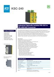
WIMA MKP 4<br />
D<br />
Continuation<br />
Permissible AC voltage<br />
in relation to frequency<br />
at 10) C internal temperature rise<br />
(general guide).<br />
Urms<br />
V 5<br />
2<br />
160<br />
102<br />
250 VDC<br />
5<br />
0.47 µF<br />
0.1 µF<br />
2.2 µF<br />
0.01 µF<br />
0.022 µF<br />
0.047 µF<br />
0.22 µF<br />
1000 pF<br />
2200 pF<br />
4700 pF<br />
2<br />
10 µF<br />
22 µF<br />
1.0 µF<br />
4.7 µF<br />
101<br />
103 2 5 104 2 5 105 2 5 f 106<br />
Hz<br />
Urms<br />
V 5<br />
2<br />
100 VDC<br />
Urms<br />
V 5<br />
220<br />
2<br />
400 VDC<br />
Urms<br />
V 5<br />
400<br />
2<br />
0.01 µF<br />
0.047 µF<br />
1000 pF<br />
2200 pF<br />
4700 pF<br />
102<br />
102<br />
2200 pF<br />
102<br />
0.22 µF<br />
0.022 µF<br />
63<br />
5<br />
22 µF<br />
4.7 µF<br />
0.01 µF<br />
0.047 µF<br />
0.22 µF<br />
5<br />
1.0 µF<br />
4.7 µF<br />
0.22 µF<br />
0.047 µF<br />
0.01 µF<br />
1000 pF<br />
4700 pF<br />
0.022 µF<br />
5<br />
1000 VDC<br />
1.0 µF<br />
2.2 µF<br />
0.1 µF<br />
0.47 µF<br />
1000 pF<br />
2200 pF<br />
4700 pF<br />
1.0 µF 2.2 µF<br />
2<br />
10 µF<br />
0.47 µF<br />
2<br />
10 µF<br />
2.2 µF<br />
0.47 µF<br />
0.1 µF<br />
2<br />
0.1 µF<br />
0.022 µF<br />
33 µF<br />
101<br />
103 2 5 104 2 5 105 2 5 f 106<br />
Hz<br />
101<br />
103 2 5 104 2 5 105 2 5 f 106<br />
Hz<br />
101<br />
102 2 5 103 2 5 104 2 5 f 105<br />
Hz<br />
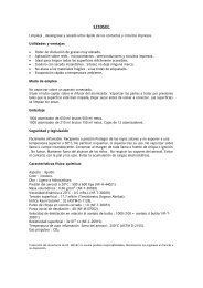
WIMA MKS 4<br />
Permissible AC voltage in relation to frequency at 10) C internal temperature rise (general guide).<br />
Urms<br />
V<br />
5<br />
40<br />
2<br />
0.22 µF<br />
1.0 µF<br />
0.047 µF<br />
0.01 µF<br />
0.022 µF<br />
0,1 µF<br />
Urms<br />
V<br />
5<br />
2<br />
160<br />
250 VDC<br />
Urms<br />
V<br />
5<br />
300<br />
220<br />
10<br />
102<br />
22 µF<br />
4.7 µF<br />
1.0 µF<br />
0.01 µF<br />
102<br />
6.8 µF<br />
2.2 µF<br />
0.47 µF<br />
0.1 µF<br />
0.022 µF<br />
4700 pF<br />
1000 pF<br />
5<br />
2<br />
63 VDC<br />
22 µF<br />
100 µF<br />
220 µF<br />
2.2 µF/4.7 µF 10 µF<br />
47 µF<br />
100 µF<br />
0.47 µF<br />
5<br />
2<br />
10 µF<br />
33 µF<br />
0.22 µF<br />
0.047 µF<br />
2.2 µF<br />
0.47 µF<br />
0.1 µF<br />
1000 pF<br />
2200 pF<br />
4700 pF<br />
0.022 µF<br />
5<br />
2<br />
630 VDC<br />
4.7 µF<br />
1.0 µF<br />
0.22 µF<br />
0.047 µF<br />
2200 pF<br />
0.01 µF<br />
1<br />
102 2 5 103 2 5 104 2 5 f 105<br />
Hz<br />
101<br />
102 2 5 103 2 5 104 2 5 f 105<br />
Hz<br />
101<br />
102 2 5 103 2 5 104 2 5 f 105<br />
Hz<br />
Urms<br />
V<br />
5<br />
2<br />
100 VDC<br />
Urms<br />
V<br />
5<br />
200<br />
400 VDC<br />
Urms<br />
V<br />
5<br />
400<br />
2<br />
2200 pF<br />
0.01 µF<br />
102<br />
0.01 µF<br />
4700 pF<br />
2200 pF<br />
1000 pF<br />
102<br />
4.7 µF<br />
1.0 µF<br />
0.22 µF<br />
0.047 µF<br />
0.01 µF<br />
1000 pF<br />
102<br />
0.047 µF<br />
1000 pF<br />
4700 pF<br />
63<br />
5<br />
2<br />
47 µF<br />
100 µF<br />
10 µF<br />
22 µF<br />
68 µF<br />
2.2 µF<br />
0.1 µF<br />
0.47 µF<br />
4.7 µF<br />
1.0 µF<br />
0.022 µF<br />
0.22 µF<br />
0.047 µF<br />
5<br />
2<br />
15 µF<br />
10 µF<br />
2.2 µF<br />
0.47 µF<br />
2200 pF<br />
4700 pF<br />
0.1 µF<br />
0.022 µF<br />
5<br />
2<br />
1000 VDC<br />
1500 VDC<br />
2000 VDC<br />
3.3 µF<br />
0.22 µF<br />
1.0 µF<br />
2.2 µF<br />
0.022 µF<br />
0.1 µF<br />
0.47 µF<br />
101<br />
102 2 5 103 2 5 104 2 5 f 105<br />
Hz<br />
101<br />
10 2 5 10 2 5 10 2 5 f 10 Hz<br />
101<br />
102 2 5 103 2 5 104 2 5 f 105<br />
Hz<br />
Technical information and general data see page 53.<br />
06.05<br />
64
Recommendation for Processing<br />
and Application of<br />
Through-Hole Capacitors<br />
D<br />
Soldering Process<br />
A preheating of through-hole WIMA<br />
capacitors is allowed for temperatures<br />
T max < 100 ° C.<br />
In practice a preheating duration of<br />
t < 5 min. has been proven to be best.<br />
Single wave soldering<br />
Soldering bath temperature: T < 260 ° C<br />
Immersion time:<br />
t < 5 sec<br />
Double wave soldring<br />
Soldering bath temperature: T < 260 ° C<br />
Immersion time:<br />
2 x t < 3 sec<br />
Wave soldering<br />
T<br />
260<br />
240<br />
220<br />
200<br />
180<br />
160<br />
140<br />
120<br />
100<br />
80<br />
60<br />
40<br />
20<br />
[°C]<br />
see detailenlargement<br />
10 s<br />
30 60 90 120 150 180 210 240 [ sec]<br />
Temperature/time graph for the maximum permissible solder bath<br />
temperature for the wave soldering of through-hole WIMA capacitors<br />
2s<br />
3s<br />
t<br />
WIMA Quality and Environmental Philosophy<br />
ISO 9001:2000 Certification<br />
ISO 9001:2000 is an international basic<br />
standard of quality assurance systems for<br />
all branches of industry. The approval<br />
according to ISO 9001:2000 of our<br />
factories by the VDE inspectorate certifies<br />
that organisation, equipment and monitoring<br />
of quality assurance in our factories<br />
correspond to internationally recognized<br />
standards.<br />
WIMA WPCS<br />
The WIMA Process Control System (WPCS)<br />
is a quality surveillance and optimization<br />
system developed by WIMA. WPCS is a<br />
major part of the quality-oriented WIMA<br />
production. Points of application of WPCS<br />
during production process:<br />
” incoming material inspection<br />
” metallization<br />
” film inspection<br />
” schoopage<br />
” pre-healing<br />
” lead attachment<br />
” cast resin preparation/<br />
encapsulation<br />
” 100% final inspection<br />
” AQL check<br />
WIMA Environmental Policy<br />
All WIMA capacitors, irrespective of<br />
whether through-hole devices or SMD,<br />
are made of environmentally friendly<br />
materials. Neither during manufacture<br />
nor in the product itself any toxic substances<br />
are used, e.g.<br />
– Lead – PBB/PBDE<br />
– PCB – Arsenic<br />
– CFC – Cadmium<br />
– Hydrocarbon chloride – Mercury<br />
– Chromium 6+ – etc.<br />
We merely use pure, recyclable materials<br />
for packing our components, such as:<br />
” carton<br />
” cardboard<br />
” adhesive tape made of paper<br />
” polystyrene<br />
We almost completely refrain from using<br />
packing materials such as:<br />
” foamed polystyrene (Styropor®)<br />
” adhesive tapes made of plastic<br />
” metal clips<br />
RoHS Compliance<br />
According to the RoHS Directive 2002/95/EC<br />
certain hazardous substances like e.g. lead,<br />
cadmium, mercury must not be used any<br />
longer in electronic equipment as of July 1st,<br />
2006. For the sake of the environment WIMA<br />
has refraind from using such substances since<br />
years already.<br />
Tape for lead-free WIMA capacitors<br />
ISO 14001:2005<br />
WIMA’s environmental management has<br />
been established in accordance with the<br />
guidelines of ISO 14001. The certification<br />
is under preparation and is expected to be<br />
accomplished by June 2006.<br />
06.05<br />
16
t<br />
Typical Dimensions for<br />
Taping Configuration<br />
D<br />
H1<br />
P 1<br />
P 2<br />
P 0<br />
P<br />
W2<br />
h<br />
H<br />
W0<br />
W1<br />
Diagram 1:<br />
PCM 2.5/5/7.5mm<br />
W<br />
D 0<br />
F<br />
d<br />
P<br />
P<br />
P 1<br />
H1<br />
P 1<br />
P 0<br />
H<br />
d<br />
d<br />
F<br />
P 0<br />
P 2<br />
F<br />
P 2<br />
Diagram 2: PCM 10/15 mm<br />
Diagram 3: PCM 22.5 and 27.5*mm<br />
*PCM 27.5 taping possible with two feed holes between components<br />
Dimensions for Radial Taping<br />
Designation Symbol PCM 2.5 taping PCM 5 taping PCM 7.5 taping PCM 10 taping* PCM 15 taping* PCM 22.5 taping PCM 27.5 taping<br />
Carrier tape width W 18.0 p0.5 18.0 p0.5 18.0 p0.5 18.0 p0.5 18.0 p0.5 18.0 p0.5 18.0 p0.5<br />
Hold-down tape width W 0 6.0 for hot-sealing adhesive tape<br />
6.0 for hot-sealing adhesive tape<br />
12.0 for hot-sealing adhesive tape<br />
12.0 for hot-sealing adhesive tape<br />
12.0 for hot-sealing adhesive tape<br />
12.0 for hot-sealing adhesive tape<br />
for hot-sealing<br />
12.0<br />
adhesive tape<br />
Hole position W 1 9.0 p0.5 9.0 p0.5 9.0 p0.5 9.0 p0.5 9.0 p0.5 9.0 p0.5 9.0 p0.5<br />
Hold-down tape position W 2 0.5 to 3.0 max. 0.5 to 3.0 max. 0.5 to 3.0 max. 0.5 to 3.0 max. 0.5 to 3.0 max. 0.5 to 3.0 max. 0.5 to 3.0 max.<br />
Feed hole diameter D 0 4.0 p0.2 4.0 p0.2 4.0 p0.2 4.0 p0.2 4.0 p0.2 4.0 p0.2 4.0 p0.2<br />
Pitch of component P 12.7 p1.0 12.7 p1.0 12.7 p1.0 25.4 p1.0 25.4 p1.0 38.1 p1.5 3 * 8.1 p1.5 or 50.8 p1.5<br />
Feed hole pitch P 0<br />
cumulative pitch cumulative pitch cumulative pitch cumulative pitch cumulative pitch cumulative pitch cumulative pitch<br />
12.7 p0.3 error max. 12.7 p0.3 error max. 12.7 p0.3 error max. 12.7 p0.3 error max. 12.7 p0.3 error max. 12.7 p0.3 error max. 12.7 p0.3 error max.<br />
1.0 mm/20 pitch 1.0 mm/20 pitch 1.0 mm/20 pitch 1.0 mm/20 pitch 1.0 mm/20 pitch 1.0 mm/20 pitch 1.0 mm/20 pitch<br />
Feed hole centre<br />
to lead<br />
P 1 5.1 p0.5 3.85 p0.7 2.6 p0.7 7.7 p0.7 5.2 p0.7 7.8 p0.7 5.3 p0.7<br />
Hole centre to<br />
component centre<br />
P 2 6.35 p1.3 6.35 p1.3 6.35 p1.3 12.7 p1.3 12.7 p1.3 19.05 p1.3 19.05 p1.3<br />
Feed hole centre to bottom<br />
16.5 p0.3 16.5 p0.3 16.5 p0.5 16.5 p0.5 16.5 p0.5 16.5 p0.5 16.5 p0.5<br />
H v<br />
edge of the component 18.5 p0.5 18.5 p0.5 18.5 p0.5 18.5 p0.5 18.5 p0.5 18.5 p0.5 18.5 p0.5<br />
Feed hole centre to top<br />
H+H<br />
H component < H 1 H+H component < H 1 H+H component < H 1 H+H component < H 1 H+H component < H 1 H+H component < H 1 H+H component < H 1<br />
edge of the component 1<br />
32.25 max. 32.25 max. 24.5 to 31.5 25.0 to 31.5 26.0 to 37.0 30.0 to 43.0 35.0 to 45.0<br />
Lead spacing at<br />
F 2.5 p0.5 5.0 +0.8 7.5 p0.8 10.0 p0.8 15 p0.8 22.5 p0.8 27.5 p0.8<br />
upper edge of carrier tape –0.2<br />
Lead diameter d 0.4 p0.05 0.5 p0.05<br />
„<br />
0.5 p0.05 or 0.7 –0.05<br />
+0.07 +0.07 +0.08 +0.08 +0.08 +0.1<br />
„<br />
0.5 p0.05 or 0.7 –0.05<br />
0.8 –0.05<br />
0.8 –0.05<br />
„<br />
0.8 –0.05<br />
or 1.0 –0.05<br />
Component alignment Dh p 2.0 max. p 2.0 max. p 3.0 max. p 3.0 max. p 3.0 max. p 3.0 max. p 3.0 max.<br />
Total tape thickness t 0.7 p0.2 0.7 p0.2 0.7 p0.2 0.7 p0.2 0.7 p0.2 0.7 p0.2 0.7 p0.2<br />
Package<br />
(see also page 101)<br />
v<br />
ROLL/AMMO<br />
REEL P 360 max. 52 p2 depending on<br />
P 30 p1<br />
B<br />
58 p2 comp. dimensions<br />
Unit see details page 103.<br />
v Please give „H“ dimensions and desired packaging type when ordering.<br />
Dims in mm.<br />
„<br />
Diameter of leads see General Data.<br />
Please clarify customer-specific deviations with the manufacturer.<br />
* PCM 10 and PCM 15 can be crimped to PCM 7.5.<br />
Position of components according to PCM 7.5 (sketch 1). P 0 = 12.7 or 15.0 is possible<br />
REEL<br />
P 360 max.<br />
B<br />
P 30 p1<br />
AMMO<br />
52 p2 54 p2 depending<br />
P 500 max.<br />
58 p2 or REEL<br />
B 60 p2 on PCM and<br />
P 25 p1<br />
66 p2<br />
68 p2 component dimensions<br />
10.05<br />
100