1 Bâ¦C 3700-2200 Silicon-Bridge Rectifiers Silizium ...
1 Bâ¦C 3700-2200 Silicon-Bridge Rectifiers Silizium ...
1 Bâ¦C 3700-2200 Silicon-Bridge Rectifiers Silizium ...

Create successful ePaper yourself
Turn your PDF publications into a flip-book with our unique Google optimized e-Paper software.
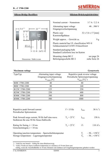
B…C <strong>3700</strong>-<strong>2200</strong><strong>Silicon</strong>-<strong>Bridge</strong> <strong>Rectifiers</strong><strong>Silizium</strong>-BrückengleichrichterDimensions / Maße in mmNominal current – NennstromAlternating input voltageEingangswechselspannungPlastic caseKunststoffgehäuseWeight approx. – Gewicht ca.3.7 A / 2.2 A40…500 V32 x 5.6 x 17 [mm]Plastic material has UL classification 94V-0Gehäusematerial UL94V-0 klassifiziertStandard packaging bulkStandard Lieferform lose im Karton9 gMounting clamp BO 2 see page 26Befestigungsschelle BO 2 siehe Seite 26Maximum ratingsTypeTypAlternating input voltageEingangswechselspannungV VRMS [V]GrenzwerteRepetitive peak reverse voltagePeriodische SpitzensperrspannungV RRM [V] 1 )B40C <strong>3700</strong>-<strong>2200</strong> 40 80B80C <strong>3700</strong>-<strong>2200</strong> 80 160B125C <strong>3700</strong>-<strong>2200</strong> 125 250B250C <strong>3700</strong>-<strong>2200</strong> 250 600B380C <strong>3700</strong>-<strong>2200</strong> 380 800B500C <strong>3700</strong>-<strong>2200</strong> 500 1000Repetitive peak forward current f > 15 Hz I FRM 30 A 2 )Periodischer SpitzenstromPeak forward surge current, 50 Hz half sine-wave T A = 25C I FSM 150 AStoßstrom für eine 50 Hz Sinus-HalbwelleRating for fusing, t < 10 ms T A = 25C i 2 t 110 A 2 sGrenzlastintegral, t < 10 msOperating junction temperature – Sperrschichttemperatur T j – 50...+150CStorage temperature – Lagerungstemperatur T S – 50...+150C1) Valid for one branch – Gültig für einen Brückenzweig2) Valid, if leads are kept at ambient temperature at a distance of 10 mm from caseGültig, wenn die Anschlußdrähte in 10 mm Abstand vom Gehäuse auf Umgebungstemperatur gehalten werden© by SEMIKRON 020404 1
B…C <strong>3700</strong>-<strong>2200</strong>CharacteristicsKennwerteMax. fwd. current without cooling fin T A = 50C R-load I FAV 2.7 ADauergrenzstrom ohne Kühlblech C-load I FAV 2.2 AMax. current with cooling fin 300 cm 2 T A = 50C R-load I FAV 4.8 ADauergrenzstrom mit Kühlblech 300 cm 2 C-load I FAV 3.7 ALeakage current – Sperrstrom T j = 25C V R = V RRM I R < 10 AThermal resistance junction to ambient air R thA < 25 K/W 1 )Wärmewiderstand Sperrschicht – umgebende LuftTypeTypMax. admissible load capacitorMax. zulässiger LadekondensatorC L [F]Min. required protective resistorMin. erforderl. SchutzwiderstandR t []B40C <strong>3700</strong>-<strong>2200</strong> 5000 0.5B80C <strong>3700</strong>-<strong>2200</strong> 2500 1.0B125C <strong>3700</strong>-<strong>2200</strong> 1500 2.0B250C <strong>3700</strong>-<strong>2200</strong> 800 4.0B380C <strong>3700</strong>-<strong>2200</strong> 600 5.0B500C <strong>3700</strong>-<strong>2200</strong> 400 6.51) Without cooling fin – Ohne Kühlblech2) Valid for one branch – Gültig für einen Brückenzweig2 020404 © by SEMIKRON