Q-System Presentation - Bushveld Conference - Nov - Geohart ...
Q-System Presentation - Bushveld Conference - Nov - Geohart ...
Q-System Presentation - Bushveld Conference - Nov - Geohart ...

Create successful ePaper yourself
Turn your PDF publications into a flip-book with our unique Google optimized e-Paper software.
Impala Platinum Limited<br />
Rock Engineering
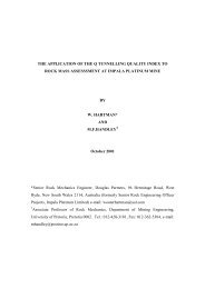
The Application Of The Q-Q<br />
Tunneling Quality Index<br />
To Rock Mass Assessment<br />
At Impala Platinum Mine<br />
Wouter Hartman<br />
Snr Rock Engineer –<br />
Projects - 2000
1. Introduction<br />
2. Locality Plan<br />
3. Geological Setting<br />
4. Problem<br />
4.1 FOG Analysis<br />
4.2 Rock Mass Classification <strong>System</strong>s<br />
4.3 Q-<strong>System</strong> Q<br />
Applicability to Impala<br />
5. Case Studies<br />
5.1 Q-<strong>System</strong> Q<br />
Methodology<br />
5.2 Q-Index Q<br />
Analysis for 10 Level Crosscut & 23 Level<br />
Conveyor<br />
5.3 Bolt Length Design for permanent mine openings<br />
6. Conclusions
Introduction<br />
Questions remain on how to properly<br />
design support in a quasi-static<br />
static<br />
environment using rock mass<br />
characteristics as an indicator and design<br />
tool<br />
EMPIRICALLY
1. Introduction<br />
2. Locality Plan<br />
3. Geological Setting<br />
4. Problem<br />
4.1 FOG Analysis<br />
4.2 Rock Mass Classification <strong>System</strong>s<br />
4.3 Q-<strong>System</strong> Q<br />
Applicability to Impala<br />
5. Case Studies<br />
5.1 Q-<strong>System</strong> Q<br />
Methodology<br />
5.2 Q-Index Q<br />
Analysis for 10 Level Crosscut & 23 Level<br />
Conveyor<br />
5.3 Bolt Length Design for permanent mine openings<br />
6. Conclusions
Locality Plan
1. Introduction<br />
2. Locality Plan<br />
3. Geological Setting<br />
4. Problem<br />
4.1 FOG Analysis<br />
4.2 Rock Mass Classification <strong>System</strong>s<br />
4.3 Q-<strong>System</strong> Q<br />
Applicability to Impala<br />
5. Case Studies<br />
5.1 Q-<strong>System</strong> Q<br />
Methodology<br />
5.2 Q-Index Q<br />
Analysis for 10 Level Crosscut & 23 Level<br />
Conveyor<br />
5.3 Bolt Length Design for permanent mine openings<br />
6. Conclusions
Geological Setting<br />
Average<br />
Unit<br />
Rock Type<br />
Thickness (m)<br />
34 HW5 Mottled and spotted Anorthosite<br />
3-6 HW4 Spotted Anorthosite (SA)<br />
5-7 HW3 Mottled Anorthosite (MA)<br />
1,5-3 HW2 Spotted Anorthositic Norite<br />
2-6 HW1 Norite<br />
2-3 Bastard Pyroxenite Pyroxenite, Coarse Grained<br />
2-3 M3 Mottled Anorthosite<br />
3-7 M2 Spotted Anorthositic Norite<br />
0,5 M1 Norite<br />
1-1,5 Merensky Medium to Coarse grain Pyroxenite<br />
0,8<br />
Pyroxenite<br />
Merensky Reef Chromitite Layer - Pegmatoid<br />
0,4 FW1 Spotted Anorthositic Norite (SAN)<br />
0,2 FW2 Cyclic Unit (Pyroxenite-SAN-MA)<br />
3-5 FW3 Spotted Anorthositic Norite<br />
0,1-0,3 FW4 Mottled Anorthosite<br />
1-3 FW5 Spotted Anorthositic Norite<br />
1-3 FW6 Cyclic Unit (MA-SA-MA)<br />
1-3 FW7 Spotted Anorthositic Norite<br />
0,8-1,2 FW8 Spotted Anorthosite<br />
3-6 FW9 Mottled Anorthosite<br />
3-5 FW10 Spotted Anorthositic Norite<br />
12-15 FW11 Spotted Anorthosite<br />
10-12 FW12 Mottled Anorthosite<br />
5-7 UG2 Pyroxenite with Leader Chromitite<br />
0,7 UG2 Reef<br />
Stringers<br />
Chromitite<br />
10-12 FW UG2 Pegmatoid<br />
5-7 FW13 Spotted Anorthositic Norite
1. Introduction<br />
2. Locality Plan<br />
3. Geological Setting<br />
4. Problem<br />
4.1 FOG Analysis<br />
4.2 Rock Mass Classification <strong>System</strong>s<br />
4.3 Q-<strong>System</strong> Q<br />
Applicability to Impala<br />
5. Case Studies<br />
5.1 Q-<strong>System</strong> Q<br />
Methodology<br />
5.2 Q-Index Q<br />
Analysis for 10 Level Crosscut & 23 Level<br />
Conveyor<br />
5.3 Bolt Length Design for permanent mine openings<br />
6. Conclusions
PROBLEM<br />
• Support Design Based On Total Fatality Fall Of<br />
Ground 95% Cumulative Analysis<br />
• When Accident Statistics Are Split Into Stoping &<br />
Development : The Latter Was Found To Be<br />
Limiting To Properly Design Support<br />
• Design Development Support Using 50 kN/m2 Or<br />
Use Rock Mass Quality and Excavation Size As<br />
Design Criterion
PROBLEM<br />
FOG FATALITY ANALYSIS 95% CUMULATIVE - DEVELOPMENT<br />
FREQUENCY PLOT<br />
9<br />
8<br />
7<br />
6<br />
5<br />
4<br />
3<br />
2<br />
1<br />
0<br />
100%<br />
90%<br />
80%<br />
70%<br />
60%<br />
50%<br />
40%<br />
30%<br />
20%<br />
10%<br />
0%<br />
CUMULATIVE<br />
PERCENTAGE<br />
0.0<br />
0.2<br />
0.4<br />
0.6<br />
0.8<br />
1.0<br />
1.2<br />
1.4<br />
More<br />
THICKNESS FOG's ( metres )
PROBLEM<br />
FOG FATALITY ANALYSIS - GEOMETRIES<br />
Scaling<br />
32%<br />
Block<br />
50%<br />
Wedge<br />
18%
PROBLEM<br />
FOG FATALITY ANALYSIS - BOUNDARIES<br />
Chromitite<br />
Layer 27%<br />
Dykes<br />
4%<br />
Faults<br />
6%<br />
Joints<br />
63%
PROBLEM<br />
ROCK MASS CLASSIFICATION SYSTEMS<br />
1. Terzhagi’s<br />
2. RQD<br />
3. Rock Structure Rating (RSR)<br />
4. CSIR Geomechanics Classification<br />
for jointed rock mass<br />
5. Modifications to RMR for mining<br />
6. Stini & Lauffer Classifications<br />
7. Checklist methodology for hazard<br />
identification in tunnels<br />
8. Rockwall Condition Factor (RCF)<br />
9. Rock Tunneling Quality Index, Q
PROBLEM<br />
Q - SYSTEM APPLICABILITY TO IMPALA<br />
Q<br />
= RQD x Ja<br />
x Jw<br />
Jn Jr SRF<br />
• Simplicity as a measure of block size, inter block<br />
shear strength, active stress & all critical factors<br />
associated with fog’s<br />
• Easy to use underground<br />
• Simple relationship between support required,<br />
- no support required and tunneling Q-index Q<br />
which can be easily modified to suit changing<br />
geotechnical conditions
1. Introduction<br />
2. Locality Plan<br />
3. Geological Setting<br />
4. Problem<br />
4.1 FOG Analysis<br />
4.2 Rock Mass Classification <strong>System</strong>s<br />
4.3 Q-<strong>System</strong> Q<br />
Applicability to Impala<br />
5. Case Studies<br />
5.1 Q-<strong>System</strong> Q<br />
Methodology<br />
5.2 Q-Index Q<br />
Analysis for 10 Level Crosscut & 23 Level<br />
Conveyor<br />
5.3 Bolt Length Design for permanent mine openings<br />
6. Conclusions
CASE STUDIES<br />
Q – INDEX METHODOLOGY :<br />
• Estimating Rock Quality Designation (RQD) From Scan line<br />
Measurements<br />
Jd = D + S + V<br />
RQD = 115 – 3.3 * Jd<br />
• Jn, Jr, Ja, Jw & SRF Obtained As Described By Barton<br />
• 10m Intervals
CASE STUDIES<br />
Q – INDEX ANALYSIS :<br />
• No. 9-Shaft 9<br />
~ 10 Level Crosscut<br />
• No. 14-Shaft ~ 23 Level Conveyor Decline<br />
89 Tunneling Quality Index Measurements :<br />
• 77 Along 10 Level Crosscut<br />
• 12 Along 23 Level Conveyor<br />
representing 890m of tunnel
10 LEVEL<br />
CROSSCUT<br />
23 LEVEL<br />
CONVEYOR<br />
CASE STUDIES<br />
CASE STUDIES<br />
Distribution of Q-Index Q<br />
Values<br />
Exceptionally<br />
poor<br />
Extrem ely<br />
Poor<br />
Very Poor<br />
Poor<br />
Fair<br />
G ood<br />
Very G ood<br />
Extrem ely<br />
G ood<br />
40<br />
30<br />
20<br />
10<br />
0<br />
Q - VALUE CATEGORIES<br />
QUANTITY
CASE STUDIES<br />
NO. 9-SHAFT9<br />
10 LEVEL CROSSCUT
CASE STUDIES<br />
NO. 9-SHAFT9<br />
10 LEVEL CROSSCUT
CASE STUDIES<br />
NO. 14-SHAFT<br />
23 LEVEL CONVEYOR DECLINE
CASE STUDIES<br />
NO. 14-SHAFT<br />
23 LEVEL CONVEYOR DECLINE
CASE STUDIES<br />
Rock Mass Quality, Q, vs Equivalent Dimension - Plot<br />
100<br />
Equivalent<br />
Dim ension<br />
10<br />
1<br />
0.1 1 10 100 1000<br />
Rock Mass Quality Q<br />
Unsupported -<br />
Barton<br />
Unsupported -<br />
Hartman<br />
23 Level<br />
Conveyor<br />
10 Level<br />
Crosscut
CASE STUDIES<br />
Rock Mass Quality, Q, vs Unsupported Span - Plot<br />
Unsupported Sp an ( m )<br />
1000<br />
100<br />
10<br />
1<br />
0.1 1 10 100 1000<br />
Rock Mass Quality Q<br />
Unsupported<br />
- Barton<br />
Unsupported<br />
- Hartman<br />
10 Level<br />
Crosscut<br />
23 Level<br />
Conveyor
CASE STUDIES<br />
Barton Formulas :<br />
Equivalent Dimension = 2 * Q 0.4<br />
Unsupported Span = 2 * ESR * Q 0.4<br />
Hartman Modified Formulas :<br />
Equivalent Dimension = 1,56 * Q 0.3442<br />
Unsupported Span = 1,56 * ESR * Q 0.3442
CASE STUDIES<br />
Bolt Length Design for Permanent Mine Openings<br />
From Barton et al :<br />
L = 2 + 0.15*B<br />
ESR<br />
Where,<br />
L - bolt length;<br />
B - excavation width;<br />
ESR (Excavation Support Ratio) - a value related to the<br />
intended use of the excavation and the degree of security, which<br />
is demanded of the system - For permanent mine openings the<br />
ESR = 1.6.
1. Introduction<br />
2. Locality Plan<br />
3. Geological Setting<br />
4. Problem<br />
4.1 FOG Analysis<br />
4.2 Rock Mass Classification <strong>System</strong>s<br />
4.3 Q-<strong>System</strong> Q<br />
Applicability to Impala<br />
5. Case Studies<br />
5.1 Q-<strong>System</strong> Q<br />
Methodology<br />
5.2 Q-Index Q<br />
Analysis for 10 Level Crosscut & 23 Level<br />
Conveyor<br />
5.3 Bolt Length Design for permanent mine openings<br />
6. Conclusions
FOG Analysis :<br />
Conclusions<br />
• 95% of all falls of ground were 0,9m<br />
thick or less<br />
• nearly all falls of ground were related to<br />
discontinuities in the rock mass<br />
• large falls of ground are infrequent<br />
• conventional support would have been<br />
sufficient to prevent falls of ground
Conclusions ( (CONT. CONT.)<br />
Tunnel Quality Index Application :<br />
• potentially large falls of ground should<br />
be prevented by investigations & revealing<br />
un-favourable orientations of<br />
discontinuities<br />
• support to be introduced into tunnels<br />
with spans in excess of the modified<br />
prediction<br />
• no rockmass classification systems are<br />
general & require some modification in<br />
a specific environment