Electrical Aspects of a Märklin HO Layout - Atarrabi
Electrical Aspects of a Märklin HO Layout - Atarrabi
Electrical Aspects of a Märklin HO Layout - Atarrabi

Create successful ePaper yourself
Turn your PDF publications into a flip-book with our unique Google optimized e-Paper software.
Eckert Engineering Technical Notes Page 12 <strong>of</strong> 15<br />
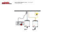
Picture two trains, Train A and Train B (not shown) traveling clockwise. They can control each other<br />
on the above layout with the following logic:<br />
1. Train A is stopped at the block, because the 7039 signal is red.<br />
2. Train B passes over the circuit track “GO”; 7039 signal turns green; block has power.<br />
3. Train A starts because <strong>of</strong> green signal; leaves block; passes over the circuit track “STOP”; 7039<br />
signal turns red; block has no power. Both trains moving now.<br />
4. Train B arrives at block; stops because the 7039 signal is red.<br />
5. Train A passes over the circuit track “GO”......... this becomes an endless loop.<br />
8.0 Multiple Transformers on <strong>Layout</strong>s<br />
Medium size and larger layouts need multiple transformers to supply enough power. When two or<br />
more transformers are used in a layout, it is important that they be connected with “Correct Polarity”.<br />
This section will explain the phenomena involved, and how to test for correct polarity.<br />
8.1 The Phenomena <strong>of</strong> Polarity Correct polarity is the same as “In Phase”; which means that the<br />
voltage peaks and valleys <strong>of</strong> two or more transformers’ AC outputs are in sync with each other. The<br />
output <strong>of</strong> a transformer (secondary) is in the same phase as its input (110 volt primary). Thus, if a<br />
transformer’s output is found to be “out <strong>of</strong> phase” with the others, simply rotating the input 110-volt<br />
plug will bring it “in phase”.<br />
TRANSFORMERS “OUT OF PHASE” (this is bad)<br />
+8 Volts<br />
Transformer #1 Output<br />
(Yellow #1 vs. Brown Ground)<br />
-8 Volts<br />
+8 Volts<br />
Transformer #2 Output<br />
(Yellow #2 vs. Brown Ground)<br />
-8 Volts<br />
+16 Volts<br />
Differential<br />
Transformer #1 - Transformer #2<br />
(Yellow #1 vs. Yellow #2)<br />
(& Brown #1 connected to Brown #2)<br />
-16 Volts<br />
TRANSFORMERS “IN PHASE” (this is good)<br />
+8 Volts<br />
Transformer #1 Output<br />
(Yellow #1 vs. Brown Ground)<br />
-8 Volts<br />
+8 Volts<br />
Transformer #2 Output<br />
(Yellow #2 vs. Brown Ground)<br />
-8 Volts<br />
+16 Volts<br />
Differential<br />
Transformer #1 - Transformer #2<br />
(Yellow #1 vs. Yellow #2)<br />
(& Brown #1 connected to Brown #2)<br />
-16 Volts<br />
Questions? Call Timothy Eckert, (704) 547-6058 days, (704) 784-4387 evenings, or EckertT@epri.com