Electrical Aspects of a Märklin HO Layout - Atarrabi
Electrical Aspects of a Märklin HO Layout - Atarrabi
Electrical Aspects of a Märklin HO Layout - Atarrabi

Create successful ePaper yourself
Turn your PDF publications into a flip-book with our unique Google optimized e-Paper software.
Eckert Engineering Technical Notes Page 14 <strong>of</strong> 15<br />
8.3 Polarity Test Procedure The <strong>Märklin</strong> transformers do not have polarized plugs (a plug with<br />
one prong wider than the other); this procedure will rotate the plugs to ensure that all <strong>of</strong> the<br />
transformers are in “phase” with each other.<br />
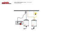
1 2 3<br />
1. Remove all existing layout plugs from transformer sockets.<br />
2. Plug all transformers into a multiple outlet plug strip that has an On/Off switch.<br />
3. Connect all grounds together with brown wires and plugs at the ground (0) sockets as shown.<br />
4. Turn the knob <strong>of</strong> each transformer to a mid position such as “100”.<br />
5. Connect a 16 volt lamp (i.e., 7073, used for lighting a building) across the red track power sockets<br />
<strong>of</strong> Transformers #1 and #2. Note that such a light usually has 1 yellow wire and 1 brown wire; it<br />
does not matter which wire plugs into which transformer.<br />
6. The 110 Volt wall plug for Transformer #1 is correct by default. Turn the outlet plug strip ON. If<br />
the bulb lights medium to bright, rotate the 110 Volt wall plug <strong>of</strong> Transformer #2 180 degrees.<br />
The bulb should now be dark, or with just a faint glow. Now the wall plug for Transformer #2 is<br />
correct.<br />
7. Connect the 16 volt lamp across the red track power sockets <strong>of</strong> Transformers #1 and #3. If the<br />
bulb lights medium to bright, rotate the 110 Volt wall plug <strong>of</strong> Transformer #3 180 degrees. The<br />
bulb should now be dark, or with just a faint glow. Now the wall plug for Transformer #3 is<br />
correct.<br />
8. Continue the above step for each remaining Transformer.<br />
9. Paint a dab <strong>of</strong> white paint or “whiteout” to the top <strong>of</strong> all plugs for future reference.<br />
10. When you want to turn <strong>of</strong>f the layout, use the On/Off switch <strong>of</strong> the multiple outlet plug strip. Do<br />
NOT unplug each transformer (doing so opens up the chance to have the transformers with<br />
incorrect polarity when they are plugged back in). However, if a single transformer must be<br />
removed from the layout and then reinstalled, matching the dabs <strong>of</strong> white paint will help to reinstall<br />
it correctly. If a new transformer is to be added to the layout, repeat Steps 2-7 <strong>of</strong> this procedure.<br />
(An alternate test procedure uses the yellow sockets <strong>of</strong> the transformers instead <strong>of</strong> the red sockets; this<br />
has the advantage <strong>of</strong> not needing to position the control knobs in Step 4. However, if the polarity is<br />
wrong the voltage applied to the bulb will be about 32 volts, which possibly could burn out the bulb. A<br />
voltage meter can be used instead <strong>of</strong> a bulb. In such cases, using the yellow sockets is preferred.)<br />
Questions? Call Timothy Eckert, (704) 547-6058 days, (704) 784-4387 evenings, or EckertT@epri.com