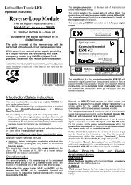
TurnTable-Decoder TT-DEC-R
TurnTable-Decoder TT-DEC-R
TurnTable-Decoder TT-DEC-R

You also want an ePaper? Increase the reach of your titles
YUMPU automatically turns print PDFs into web optimized ePapers that Google loves.
Littfinski DatenTechnik (LDT)<br />
Kleiner Ring 9 • 25492 Heist • Tel: 04122 / 977 381 • Fax: 04122 / 977 382<br />
Speed<br />
KL1<br />
Multi-Digital<br />
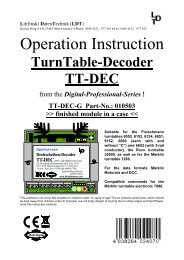
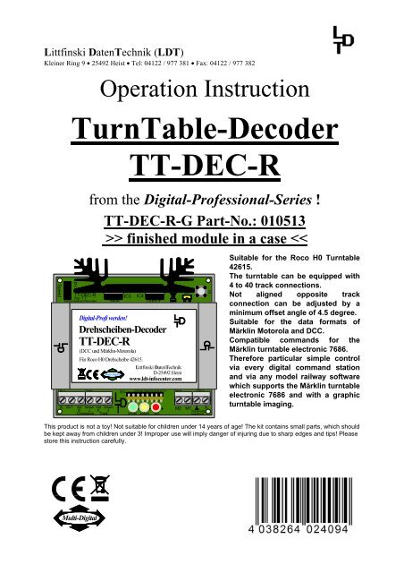
Operation Instruction<br />
<strong>TurnTable</strong>-<strong>Decoder</strong><br />
P1<br />
<strong>TT</strong>-<strong>DEC</strong>-R<br />
Rev. 1.1<br />
Drehscheiben-<strong>Decoder</strong><br />
<strong>TT</strong>-<strong>DEC</strong>-R<br />
from the Digital-Professional-Series !<br />
<strong>TT</strong>-<strong>DEC</strong>-R-G Part-No.: 010513<br />
>> finished module in a case
<strong>TT</strong>-<strong>DEC</strong>-R – Manual<br />
Index: Page<br />
1. Preface / Safety Instruction 2<br />
2. Selecting the available turntable (old or new version) 2<br />
3. Alterations on the Roco turntable 3<br />
3.1. Free-wheeling diode soldering 3<br />
3.2. Motor cable soldering 5<br />
3.3. Bridge track contact isolation 6<br />
4. Correct position of the turntable sliding switches and the setting<br />
or removing of the matching jumper JP1 of the <strong>TT</strong>-<strong>DEC</strong>-R 7<br />
5. <strong>TT</strong>-<strong>DEC</strong>-R connection to the digital layout and to the turntable 7<br />
5.1. <strong>TT</strong>-<strong>DEC</strong>-R connection to the digital layout 7<br />
5.2. <strong>TT</strong>-<strong>DEC</strong>-R connection to the turntable 9<br />
5.2.1. <strong>TT</strong>-<strong>DEC</strong>-R connection to old version 9<br />
5.2.2. <strong>TT</strong>-<strong>DEC</strong>-R connection to new version 10<br />
6. Turntable-<strong>Decoder</strong> <strong>TT</strong>-<strong>DEC</strong>-R programming 11<br />
6.1. Basic address and data format programming 11<br />
6.2. Turning direction testing 12<br />
6.3. Track connection programming 12<br />
6.4. Bridge track polar reversal (only 2-conductor mode) 15<br />
6.5. Turning speed adjustment 17<br />
6.6. Reference track synchronizing 18<br />
6.7. Special function: Turntable test / Factory setting 18<br />
6.8. Programming- and Control-Table 19<br />
7. Feedback reports 20<br />
8. Assembly plan 23<br />
- 1 -
<strong>TT</strong>-<strong>DEC</strong>-R – Manual<br />
1. Preface / Safety Instruction:<br />
You have purchased the <strong>TurnTable</strong>-<strong>Decoder</strong> <strong>TT</strong>-<strong>DEC</strong>-R for your model railway layout<br />
supplied within the assortment of Littfinski DatenTechnik (LDT).<br />
We are wishing you having a good time for the application of this product!<br />
The purchased unit comes with a 2 years guarantee (validity for the finished module<br />
and finished module in a case only).<br />
• Please read this instruction careful. For damages caused by disregarding this<br />
instruction the right of claiming guarantee will expire. No liability will be taken<br />
over for resultant damages. You can download this manual as a PDF-file with<br />
colored pictures from the area “Downloads” at our Web-Site. The file can be<br />
opened with the Acrobat Reader.<br />
• Attention: Carry out any connections only with disconnected model railway<br />
layout (switch-off the transformers or disconnect the main plug).<br />
2. Selecting the available turntable (old or new version):<br />
The Roco H0 Turntable 42615 is available within two different versions. The<br />
difference between the two versions is the supplied 8-poles flat ribbon cable and the<br />
supplied pc-board for the under-floor drive of the turntable. For identification which<br />
version you own please have a look at the bottom of the turntable. If there is a bore<br />
at the protection cover as per the right sketch it will be the new version. Without a<br />
bore at the protection cover it will be the old version as shown to the left.<br />
schwarz<br />
black<br />
0 1<br />
R O<br />
C O<br />
Roco Drehscheibe 42615 alte Variante<br />
Roco Turntable 42615 old version<br />
- 2 -<br />
0 1<br />
R O<br />
C O<br />
schwarz<br />
black<br />
Roco Drehscheibe 42615 neue Variante<br />
Roco Turntable 42615 new version<br />
Bohrung für zusätzliche<br />
Schraubverbindung<br />
bore for additional<br />
screwed connection
<strong>TT</strong>-<strong>DEC</strong>-R – Manual<br />
3. Alterations on the Roco Turntable:<br />
• Important Information: Any alteration on the Roco Turntable 42615 have to<br />
be completed before the Turntable-<strong>Decoder</strong> <strong>TT</strong>-<strong>DEC</strong>-R gets into first operation.<br />
An operation of the Turntable-<strong>Decoder</strong> <strong>TT</strong>-<strong>DEC</strong>-R before the electrical changes<br />
have been completed (soldering the free-wheel diode and the drive-motor<br />
cables) can eventually damage the Turntable-<strong>Decoder</strong> <strong>TT</strong>-<strong>DEC</strong>-R and as well<br />
your turntable.<br />
After completing the electrical alterations the Roco Turntable 42615 can not be<br />
controlled anymore by the Roco-Turntable remote control unit.<br />
3.1. Free-wheeling diode soldering:<br />
The free-wheeling diode 1N4003 which is attached to each supplied Turntable-<br />
<strong>Decoder</strong> <strong>TT</strong>-<strong>DEC</strong>-R has to be soldered onto the pc-board of the under-floor drive to<br />
prevent the interference of the switching voltage of the interlock coil.<br />
For this procedure please take off the protection cover of the under-floor drive<br />
mechanic as described at the Roco Manual for the turntable and read the section<br />
“Maintenance of the drive”.<br />
After removing the protection cover you can see the pc-board and the under-floor<br />
drive of the old version shown at the left draft and the new version at the right.<br />
schwarz<br />
black<br />
0 L42615-a11<br />
Roco Drehscheibe 42615 alte Variante<br />
Roco Turntable 42615 old version<br />
- 3 -<br />
0 1<br />
schwarz<br />
black<br />
42615-A11<br />
Roco Drehscheibe 42615 neue Variante<br />
Roco Turntable 42615 new version<br />
The detailed images on the next page show the wiring of the under-floor drive to the<br />
pc-board before the alteration. The old version is shown at the left and the new<br />
version at the right.
<strong>TT</strong>-<strong>DEC</strong>-R – Manual<br />
42615-a11<br />
Roco Drehscheibe 42615 alte Variante<br />
Roco Turntable 42615 old version<br />
- 4 -<br />
15-A11<br />
Roco Drehscheibe 42615 neue Variante<br />
Roco Turntable 42615 new version<br />
Please solder the diode 1N4003 onto the soldering terminals of the pc-board as<br />
shown at the two detailed images.<br />
Before soldering please shorten the connection wires of the diode 1N4003 to a<br />
length of about 1 cm and bend both wires careful at 90 degree just after the diode<br />
body.<br />
The diode 1N4003 has on one connection wire a printed ring (called cathode ring) for<br />
the correct assembly direction.<br />
The diode 1N4003 has been correct soldered at the old version if the cathode ring<br />
shows to the right respectively direct to the track connections (image left).<br />
At the new turntable version is the soldered position of the diode 1N4003 correct if<br />
the cathode ring shows to the bottom to the worm drive (image right).<br />
42615-a11<br />
Diode<br />
1N4003<br />
Roco Drehscheibe 42615 alte Variante<br />
Roco Turntable 42615 old version<br />
15-A11<br />
Diode<br />
1N4003<br />
Roco Drehscheibe 42615 neue Variante<br />
Roco Turntable 42615 new version
<strong>TT</strong>-<strong>DEC</strong>-R – Manual<br />
3.2. Motor cable soldering:<br />
Each Turntable-<strong>Decoder</strong> <strong>TT</strong>-<strong>DEC</strong>-R will be supplied together with a 2m 2-poles motor<br />
connection cable. On one side is the cable is equipped with two inductors.<br />
Originally is the motor of the under-floor drive connected to the pc-board via two<br />
wires. Remove this two cables by unsolder them from the motor connection and from<br />
the pc-board.<br />
Now solder the new motor cable to the two motor connections. Each connection<br />
wire of the inductors has to be soldered to one of the two motor connections of the<br />
under-floor drive.<br />
Which of the two inductors soldered to which of the two motor connections does no<br />
matter.<br />
Drosseln<br />
Inductors<br />
42615-a11<br />
Motorkabel<br />
motor cable<br />
Diode<br />
1N4003<br />
Roco Drehscheibe 42615 alte Variante<br />
Roco Turntable 42615 old version<br />
- 5 -<br />
15-A11<br />
Drosseln<br />
Inductors<br />
Motorkabel<br />
motor cable<br />
Diode<br />
1N4003<br />
Roco Drehscheibe 42615 neue Variante<br />
Roco Turntable 42615 new version<br />
Before replacing the protection cover of the turntable as described within the Roco<br />
Manual for the turntable within the section “Maintenance of the drive” and after<br />
completion of the alteration you have to feed the motor cable through the opening on<br />
the protection cover near the motor connections.<br />
Each Turntable-<strong>Decoder</strong> <strong>TT</strong>-<strong>DEC</strong>-R will be supplied together with a cable fastener for<br />
strain relief and for securing the motor cable onto the lower latch of the cover<br />
opening.<br />
The pictures on the following page show both turntable versions after attaching the<br />
protection cover including the motor cable after the completion of the electrical<br />
alteration.
<strong>TT</strong>-<strong>DEC</strong>-R – Manual<br />
schwarz<br />
black<br />
0 1<br />
R O<br />
C O<br />
Roco Drehscheibe 42615 alte Variante<br />
Roco Turntable 42615 old version<br />
Motorkabel<br />
motor cable<br />
3.3. Bridge track contact isolation:<br />
- 6 -<br />
0 1<br />
R O<br />
C O<br />
schwarz<br />
black<br />
Roco Drehscheibe 42615 neue Variante<br />
Roco Turntable 42615 new version<br />
Motorkabel<br />
motor cable<br />
At the supply status the Roco turntable 42615 contains on each bridge track end<br />
two slide contacts for the connection to the selected track.<br />
These slide contacts have to be removed or isolated before the turntable<br />
Decode <strong>TT</strong>-<strong>DEC</strong>-R will be set into function.<br />
For removing or isolating the four sliding contacts you should remove several<br />
access tracks respectively blind tracks as described at the manual for the Roco<br />
Turntable 42615.<br />
If you do not want to remove the four sliding contacts with a small side cutter you<br />
will have the possibility to lower the contacts to assure that no electrical contact to<br />
the track connections is possible.<br />
For this action please bend the sliding contacts carefully down and slide a little piece<br />
of cable insulation between the sliding contact and the bridge track. The sliding<br />
contact will be permanently lowered and can not provide any electrical contact to<br />
the rails of the access tracks.
<strong>TT</strong>-<strong>DEC</strong>-R – Manual<br />
4. Correct position of the turntable sliding switches and the setting or<br />
removing of the matching jumper JP1 of the <strong>TT</strong>-<strong>DEC</strong>-R:<br />
There are two sliding switches at the lower side of the turntable.<br />
One of the two sliding switches is market with a “0” and ”1”. For the operation in<br />
connection to the Turntable-<strong>Decoder</strong> <strong>TT</strong>-<strong>DEC</strong>-R this switch has always to be set onto<br />
position “1”.<br />
The second slide switch is marked with the symbol “=” and “~”. The marking “=”<br />
indicates the setting for the operation with the 2-conductor bridge track system and<br />
the marking “~” indicates the setting for the 3-conductor system.<br />
Now select the correct switch position in accordance to the used track conductor<br />
system.<br />
Additional information can be found within the Roco Manual for the turntable at the<br />
section “Selecting the driving current system”.<br />
If you use the turntable at the 2-conductor system (sliding switch at the turntable in<br />
position “=”) please remove the jumper JP1 at the <strong>TT</strong>-<strong>DEC</strong>-R. You can find this jumper<br />
at the right between the case cover and the heat sink of the Turntable-<strong>Decoder</strong> <strong>TT</strong>-<br />
<strong>DEC</strong>-R.<br />
If the operation of the turntable is used in a 3-conductor system (sliding switch of the<br />
turntable in position “~” the jumper JP1 of the Turntable-<strong>Decoder</strong> <strong>TT</strong>-<strong>DEC</strong>-R shall<br />
remain in position (supplied position).<br />
5. <strong>TT</strong>-<strong>DEC</strong>-R connection to the digital layout and to the turntable:<br />
• Important Information: Switch-off the electrical supply before performing any<br />
connection work (switch-off all transformers or unplug the main connection).<br />
5.1. <strong>TT</strong>-<strong>DEC</strong>-R connection to the digital layout:<br />
The <strong>TurnTable</strong>-<strong>Decoder</strong> <strong>TT</strong>-<strong>DEC</strong>-R receives the power supply via the two clamps at<br />
the very left side of the 6-poles connection clamp. The voltage can be between 16<br />
and 18 Volt~ (alternated voltage of a model railway transformer). Both clamps are<br />
marked accordingly.<br />
The decoder receives the digital information via the third and fourth clamp (counted<br />
from the left side) of the 6-poles connection clamp which is marked with<br />
“Commands” on the pc-board. Supply the digital information directly from the controlunit<br />
or from a booster respectively from the digital ring conductor “switching” which<br />
has been connected to all accessory decoders. To assure that the <strong>TT</strong>-<strong>DEC</strong>-R receives<br />
interference-free data do not take the digital information directly from the rails.<br />
One of the two digital clamps has been marked with red and K and the other has been<br />
marked with brown and J. The colors red and brown respectively the marking J and K<br />
will be used by most command stations.<br />
- 7 -
<strong>TT</strong>-<strong>DEC</strong>-R – Manual<br />
Vom Modellbahntrafo<br />
From transformer<br />
Von Digitalzentrale<br />
oder Booster<br />
From command station<br />
or booster<br />
gelb<br />
yellow<br />
braun<br />
brown<br />
Ringleitung "Schalten"<br />
Ring conductor "switching" braun<br />
brown<br />
Ringleitung "Fahren"<br />
Ring conductor "driving"<br />
Vom Modellbahntrafo<br />
From transformer<br />
Von Digitalzentrale<br />
oder Booster<br />
From command station<br />
or booster<br />
rot<br />
red<br />
rot<br />
red<br />
braun<br />
brown<br />
gelb<br />
yellow<br />
braun<br />
brown<br />
rot<br />
red<br />
braun<br />
brown<br />
Speed<br />
Speed<br />
KL1<br />
P1<br />
<strong>TT</strong>-<strong>DEC</strong>-R<br />
Rev. 1.1<br />
Drehscheiben-<strong>Decoder</strong><br />
Digital-Profi werden!<br />
KL2<br />
IC3 IC4<br />
Z805 LM317<br />
Drehscheiben-<strong>Decoder</strong><br />
<strong>TT</strong>-<strong>DEC</strong>-R<br />
(DCC und Märklin-Motorola)<br />
Für Roco H0 Drehscheibe 42615.<br />
Littfinski DatenTechnik<br />
Multi-Digital<br />
D-25492 Heist<br />
www.ldt-infocenter.com<br />
ST4<br />
- 8 -<br />
LED1<br />
Littfinski DatenTechnik (LDT)<br />
LED2 LED3<br />
+ + +<br />
KL3 KL4<br />
16...18V~ red brown red brown<br />
A<br />
K J K J<br />
M2 M1<br />
Rückmeldg.<br />
Commands Track<br />
green yellow red<br />
Feedback<br />
KL1<br />
P1<br />
<strong>TT</strong>-<strong>DEC</strong>-R<br />
Rev. 1.1<br />
Drehscheiben-<strong>Decoder</strong><br />
Digital-Profi werden!<br />
KL2<br />
IC3 IC4<br />
Z805 LM317<br />
Drehscheiben-<strong>Decoder</strong><br />
<strong>TT</strong>-<strong>DEC</strong>-R<br />
(DCC und Märklin-Motorola)<br />
Für Roco H0 Drehscheibe 42615.<br />
Multi-Digital<br />
ST4<br />
Littfinski DatenTechnik<br />
D-25492 Heist<br />
www.ldt-infocenter.com<br />
LED1<br />
Littfinski DatenTechnik (LDT)<br />
LED2 LED3<br />
+ + +<br />
JP1<br />
2L 3L<br />
KL3 KL4<br />
16...18V~ red brown red brown<br />
A<br />
K J K J<br />
M2 M1<br />
Rückmeldg.<br />
Commands Track<br />
green yellow red<br />
Feedback<br />
JP1<br />
2L 3L<br />
S1<br />
S1<br />
The digital-voltage for<br />
the bridge track shall<br />
be connected to the<br />
two clamps marked<br />
with “Track”. This<br />
digital voltage comes<br />
from the digital ring<br />
conductor “Driving”.<br />
This two clamps are as<br />
well marked with red<br />
and K respectively with<br />
brown and J.<br />
If you use for “Driving”<br />
and “Switching” one<br />
common digital ring<br />
conductor you have to<br />
connect the ports of<br />
the clamps<br />
“Commands” and<br />
“Track” with this<br />
common ring<br />
conductor.
<strong>TT</strong>-<strong>DEC</strong>-R – Manual<br />
5.2. <strong>TT</strong>-<strong>DEC</strong>-R connection to the digital turntable:<br />
At first please connect the two wires of the motor cable with the clamps M1 and M2 of<br />
the Turntable-<strong>Decoder</strong> <strong>TT</strong>-<strong>DEC</strong>-R. Which wire you connect to which clamp does not<br />
matter.<br />
The Roco turntable 42615 will be supplied with an 8-poles flat ribbon cable.<br />
Please attend to the differences between the flat ribbon cable of the old and the new<br />
version of the Roco turntable 42615. The ribbon-cable has to be correctly attached<br />
onto the 8-poles pc-board plug of the Turntable-<strong>Decoder</strong> <strong>TT</strong>-<strong>DEC</strong>-R.<br />
5.2.1. <strong>TT</strong>-<strong>DEC</strong>-R connection to the old version:<br />
The 8-poles flat ribbon cable of the old version of the Roco turntable 42615 contains<br />
at the ends a black flat plug. Insert the flat plug of the one side of the flat ribbon<br />
cable careful onto the pc-board socket of the <strong>TT</strong>-<strong>DEC</strong>-R that the black single wire of<br />
the flat ribbon cable shows into right direction as shown at the following picture.<br />
Vom Modellbahntrafo<br />
From transformer<br />
Von Digitalzentrale<br />
oder Booster<br />
From command station<br />
or booster<br />
Ringleitung "Fahren"<br />
Ring conductor "driving"<br />
gelb<br />
yellow<br />
braun<br />
brown<br />
rot<br />
red<br />
Ringleitung "Schalten"<br />
Ring conductor "switching" braun<br />
brown<br />
rot<br />
red<br />
braun<br />
brown<br />
Speed<br />
KL1<br />
P1<br />
<strong>TT</strong>-<strong>DEC</strong>-R<br />
Rev. 1.1<br />
Drehscheiben-<strong>Decoder</strong><br />
Roco Drehscheibe 42615 alte Variante<br />
Roco Turntable 42615 old version<br />
- 9 -<br />
Digital-Profi werden!<br />
KL2<br />
IC3 IC4<br />
Z805 LM317<br />
Drehscheiben-<strong>Decoder</strong><br />
<strong>TT</strong>-<strong>DEC</strong>-R<br />
(DCC und Märklin-Motorola)<br />
Für Roco H0 Drehscheibe 42615.<br />
Multi-Digital<br />
ST4<br />
Littfinski DatenTechnik<br />
D-25492 Heist<br />
www.ldt-infocenter.com<br />
LED1<br />
Littfinski DatenTechnik (LDT)<br />
LED2 LED3<br />
+ + +<br />
KL3 KL4<br />
16...18V~ red brown red brown<br />
A<br />
K J K J<br />
M2 M1<br />
Rückmeldg.<br />
Commands Track<br />
green yellow red<br />
Feedback<br />
schwarz<br />
black<br />
JP1<br />
2L 3L<br />
S1<br />
Motorkabel<br />
motor cable<br />
Insert the flat plug of the second side of the flat ribbon cable onto the contact reed<br />
of the turntable-under-floor drives as described at the Manual of the Roco<br />
turntable.
<strong>TT</strong>-<strong>DEC</strong>-R – Manual<br />
5.2.2. <strong>TT</strong>-<strong>DEC</strong>-R connection to the new version:<br />
The 8-poles flat ribbon cable of the new version of the Roco turntable 42615<br />
contains on each side a gray flat plug. Insert the flat plug careful onto the pc-board<br />
socket of the <strong>TT</strong>-<strong>DEC</strong>-R in direction that the black single wire of the flat ribbon cable<br />
is showing to the left as shown at the following pictures.<br />
Vom Modellbahntrafo<br />
From transformer<br />
Von Digitalzentrale<br />
oder Booster<br />
From command station<br />
or booster<br />
Ringleitung "Fahren"<br />
Ring conductor "driving"<br />
gelb<br />
yellow<br />
braun<br />
brown<br />
rot<br />
red<br />
Ringleitung "Schalten"<br />
Ring conductor "switching" braun<br />
brown<br />
rot<br />
red<br />
braun<br />
brown<br />
Speed<br />
KL1<br />
P1<br />
<strong>TT</strong>-<strong>DEC</strong>-R<br />
Rev. 1.1<br />
Drehscheiben-<strong>Decoder</strong><br />
Roco Drehscheibe 42615 neue Variante<br />
Roco Turntable 42615 new version<br />
- 10 -<br />
Digital-Profi werden!<br />
KL2<br />
IC3 IC4<br />
Z805 LM317<br />
Drehscheiben-<strong>Decoder</strong><br />
<strong>TT</strong>-<strong>DEC</strong>-R<br />
(DCC und Märklin-Motorola)<br />
Für Roco H0 Drehscheibe 42615.<br />
Multi-Digital<br />
ST4<br />
Littfinski DatenTechnik<br />
D-25492 Heist<br />
www.ldt-infocenter.com<br />
LED1<br />
Littfinski DatenTechnik (LDT)<br />
LED2 LED3<br />
+ + +<br />
KL3 KL4<br />
16...18V~ red brown red brown<br />
A<br />
K J K J<br />
M2 M1<br />
Rückmeldg.<br />
Commands Track<br />
green yellow red<br />
Feedback<br />
schwarz<br />
black<br />
JP1<br />
2L 3L<br />
S1<br />
Motorkabel<br />
motor cable<br />
Insert the flat plug of the second side of the flat ribbon cable onto the contact reed<br />
of the turntable under-floor drives as described at the Manual of the Roco<br />
turntable.
<strong>TT</strong>-<strong>DEC</strong>-R – Manual<br />
6. Turntable-<strong>Decoder</strong> <strong>TT</strong>-<strong>DEC</strong>-R programming:<br />
• Important information: You can start with the first operation and with the<br />
programming only after completing all processes of the sections 1 to 5 of this<br />
manual. Setting the unit into operation without completing the processes<br />
described within section 1 to 5 of this manual can damage the Turntable-<br />
<strong>Decoder</strong> <strong>TT</strong>-<strong>DEC</strong>-R and your turntable.<br />
Please proceed with the programming during the first operation exactly in accordance<br />
to the sequences described within the following. If you skip one of the following<br />
sections you can not expect an exact control of the digital function of your<br />
turntable via the Turntable-<strong>Decoder</strong> <strong>TT</strong>-<strong>DEC</strong>-R.<br />
6.1. Basic address and data format programming:<br />
The <strong>TurnTable</strong>-<strong>Decoder</strong> <strong>TT</strong>-<strong>DEC</strong>-R will be controlled by accessory addresses<br />
(turnout addresses) which will be used as well for switching of turnouts or signals.<br />
The command structure of the <strong>TT</strong>-<strong>DEC</strong>-R is compatible to the commands of the<br />
Märklin turntable-decoder 7686.<br />
The indication of the data format for the control of the <strong>TurnTable</strong>-<strong>Decoder</strong> <strong>TT</strong>-<strong>DEC</strong>-R<br />
from the command station (Märklin-Motorola or DCC) is not required. The data format<br />
will be automatically recognized from the <strong>TT</strong>-<strong>DEC</strong>-R during the following programming<br />
process of the basic address.<br />
With reference to the Märklin turntable-decoder 7686 is the <strong>TurnTable</strong>-<strong>Decoder</strong><br />
<strong>TT</strong>-<strong>DEC</strong>-R able to use two address sections. If you use a PC-model railway software<br />
for the control of the turntable you find mostly for the two address sections the<br />
instruction of 14 and 15. With this selection is it possible to operate 2 turntables via 2<br />
<strong>TurnTable</strong>-<strong>Decoder</strong>s <strong>TT</strong>-<strong>DEC</strong>-R on your layout.<br />
The address section 14 covers the addresses 209 till 220 and the section 15 covers<br />
the addresses 225 till 236. Only by using the full capacity of the turntable with 40 track<br />
connections all addresses within the selected address section will be required.<br />
If you use a multi-protocol command station which is able to send several data<br />
formats you have to take care that all addresses within the selected address section<br />
will be adjusted uniform to Märklin-Motorola or DCC.<br />
A table showing the coherence between address section, address and turntablefunction<br />
can be found at chapter 6.8. “Programming- and Control-Table” within this<br />
operation instruction. This table gives you as well the information about the symbols (if<br />
required) your model railway software uses for the various turntable functions.<br />
- 11 -
<strong>TT</strong>-<strong>DEC</strong>-R – Manual<br />
Programming process:<br />
1. Switch-on your digital-layout and the <strong>TurnTable</strong>-<strong>Decoder</strong> <strong>TT</strong>-<strong>DEC</strong>-R. If you<br />
want to perform the programming of the <strong>TT</strong>-<strong>DEC</strong>-R via your model railway<br />
software you have to switch-on those and adjust the turntable if required at<br />
first in accordance to the relevant instruction of the software. It is important<br />
that your model railway software supports the Märklin-turntable decoder 7686<br />
because the <strong>TT</strong>-<strong>DEC</strong>-R is compatible to the commands of the Märklin decoder.<br />
2. Please press shortly 1-times the key S1 which is located at the right side next<br />
to the <strong>TT</strong>-<strong>DEC</strong>-R heat-sink. Now the yellow LED will flash.<br />
3. Send now several times the command >Drehrichtung< (Turning Direction) at<br />
clockwise direction or anti clockwise from your digital command station or<br />
from your model railway software in accordance to the programming- and<br />
control table (chapter 6.8.). If the <strong>TT</strong>-<strong>DEC</strong>-R has recognized the command<br />
after several times sending the command this will be indicated a switched-off<br />
yellow LED.<br />
4. The <strong>TT</strong>-<strong>DEC</strong>-R will leave the programming mode automatically. All three light<br />
emitting diodes will glow.<br />
6.2. Turning direction testing:<br />
For testing the turning direction you have to send the command >Step< (clock wise)<br />
via your digital command station or via your model railway software. The turntable<br />
bridge will turn clockwise to the next track connection.<br />
If the bridge will turn anti-clockwise to the next track connection please switch off the<br />
model railway transformer which supplies the Turntable-<strong>Decoder</strong> <strong>TT</strong>-<strong>DEC</strong>-R. Now<br />
exchange the two wires of the motor cables at the clamps M1 and M2.<br />
Switch-on the model railway transformer and send again the command >Step< at<br />
clockwise direction. Now shall the bridge turn correct onto the next track<br />
connection.<br />
6.3. Track connection programming:<br />
Please attend: The adjustment of the turntable bridge turning direction has to<br />
be completed in accordance to section 6.2 to assure the clock-wise turning of the<br />
turntable bridge to the next track connection by each >Step< command before starting<br />
with the programming of the track connections.<br />
By programming the track connections you have to prepare your <strong>TurnTable</strong>-<br />
<strong>Decoder</strong> <strong>TT</strong>-<strong>DEC</strong>-R to be able to recognize all available track connections and to<br />
turn the turntable bridge to the required track connection during the operation.<br />
The turntable can be equipped with 4 to 40 track connections.<br />
- 12 -
<strong>TT</strong>-<strong>DEC</strong>-R – Manual<br />
Non-aligned opposite track connections can have an offset with a minimum angle<br />
of 4,5 degree.<br />
Roco Drehscheibe 42615<br />
Roco Turntable 42615<br />
- 13 -<br />
min. 4,5°<br />
During the programming process please define one track connection as track 1 as a<br />
so-called reference track.<br />
Programming process:<br />
1. Press 2-times shortly the key S1. The green LED flashes.<br />
2. Send now the command >InputStep< commands (clockwise or anti clockwise)<br />
to the track 1 (reference track).<br />
4. Send now with reference to the operating manual of your digital command<br />
station or your model railway software the command >Clear< or >Clear< and<br />
>Input< for storing the position of track 1 (reference track). The red LED will be<br />
shortly switched off.<br />
5. Turn now the turntable with the command >Step< clockwise to the next<br />
available track connection. Consider as well single opposite track<br />
connections.<br />
6. Store now the track connection with the command >InputStep< command but turned by 180 degree. Send<br />
additionally for the last track connection the command >End
<strong>TT</strong>-<strong>DEC</strong>-R – Manual<br />
Test now the programming by sending the command >TurnClear< or >Clear< and >Input< will be the position track 1<br />
(reference track) stored. (Programming process item 4).<br />
With the command >Step< clockwise the bridge will turn to the next available track<br />
connection. This is one single opposite track connection (track 2). With the<br />
command >Input< will be the track connection 2 stored. (programming process<br />
item 5 and 6).<br />
With the command >Step< clockwise you can proceed to the track connections 3, 4,<br />
5 and 6. Each track connection will be stored with the command >InputStep< command the bridge would turn clockwise to the reference track but<br />
turned by 180 degree (the small house will be on the right side).<br />
Therefore shall be an additional command >End< released on the track connection 6.<br />
The turntable bridge will return to track 1 (reference track) and the programming<br />
mode will be automatically closed (programming process item 7).<br />
> Input < 2<br />
> Clear <<br />
> Input <<br />
4<br />
> Input <<br />
3<br />
1<br />
6<br />
Roco Drehscheibe 42615<br />
Roco Turntable 42615<br />
- 14 -<br />
4<br />
5<br />
3<br />
> Input <<br />
6<br />
2<br />
1<br />
> Input <<br />
> End
<strong>TT</strong>-<strong>DEC</strong>-R – Manual<br />
6.4. Bridge track polar reversal (only 2-conductor mode):<br />
This section is relevant only if you use your Roco turntable 42615 in 2-conductor<br />
mode. For using the 3-conductor mode (tracks with center conductor) is no bridge<br />
track polar reversal required.<br />
As described within section 3.3. (isolation of bridge track contacts) is a complete<br />
isolation between bridge track and track connections required.<br />
On this way all turntable tracks will get constant digital current supply. The constant<br />
digital current supply to the tracks makes sense because on this way is it possible to<br />
switch even inside the shed specific locomotive-functions on or off.<br />
The bridge-track receives the digital current supply via the two with “Track” marked<br />
clamps of the Turntable-<strong>Decoder</strong> <strong>TT</strong>-<strong>DEC</strong>-R.<br />
But if the turntable bridge turns by 180 degree it will give a short circuit if the polarity<br />
of the bridge-track will not be matched to the polarity of the connection track.<br />
The Turntable-<strong>Decoder</strong> <strong>TT</strong>-<strong>DEC</strong>-R is able to change the bridge-track polarity shortcircuit<br />
free. For the bridge-track is therefore no reverse-loop module required.<br />
At first the wiring of all track-connections around the turntable has to be completed<br />
with the attention to the requirement that the opposite tracks have to have the same<br />
polarity. Therefore will be there a parting-line between two different wiring sections.<br />
As shown within the following sample connection has the brown cable of the left<br />
turntable section always to be connected with the first rail if you look clockwise to<br />
the wiring.<br />
1<br />
6<br />
Trennlinie<br />
parting line<br />
Roco Drehscheibe 42615<br />
Roco Turntable 42615<br />
4<br />
- 15 -<br />
5<br />
3<br />
6<br />
2<br />
1<br />
rot<br />
red<br />
braun<br />
brown<br />
Von Digitalzentrale<br />
oder Booster<br />
From command station<br />
or booster
<strong>TT</strong>-<strong>DEC</strong>-R – Manual<br />
At the right turntable section has the red digital cable always to be connected to the<br />
first rail if looking to the wiring in clockwise direction.<br />
If the turntable bridge is passing the parting-line between the two wiring sections the<br />
Turntable-<strong>Decoder</strong> <strong>TT</strong>-<strong>DEC</strong>-R will change the polarity of the bridge track provided<br />
that you programmed the parting-line. At the sample connection will be the partingline<br />
on the track 4 because the polarity has to be changes if clockwise turning after<br />
track 4 and anti-clockwise after track 5 has the polarity to be changed.<br />
Programming process:<br />
1. Turn the turntable bridge to the reference position. Now all LED will lighten.<br />
2. Activate now 2 times shortly the key S1. The green LED flashes.<br />
Turn now the turntable bridge clockwise with the command >Step< to the track<br />
connection with the imagined parting-line.<br />
3. Send now the command >Turning direction< clockwise or anti clockwise. The<br />
boarding line will be stored and the programming mode closed. The turning<br />
bridge will turn now automatically to the track connection 1.<br />
4. Check: Send the command >Turn< clockwise. When the turning bridge<br />
passes the parting-line (at the sample at track 4) the red LED will be shortly<br />
switched off.<br />
- 16 -
<strong>TT</strong>-<strong>DEC</strong>-R – Manual<br />
6.5. Turning speed adjustment:<br />
The moving speed of the turning-bridge can be adjusted via the potentiometer “Speed”<br />
situated at the back left side next to the heat sink. Ex-factory the setting of the<br />
potentiometer will be in center position.<br />
Potentiometer “Turntable Speed”.<br />
schneller<br />
faster<br />
Bühnengeschwindigkeit<br />
bridge speed<br />
- 17 -<br />
langsamer<br />
slower<br />
If you want to exceed the turning speed of the bridge turn the potentiometer center<br />
with a small screw driver to the left. If you turn the potentiometer center to the right<br />
the speed of the bridge will be slower.<br />
The Turntable-<strong>Decoder</strong> <strong>TT</strong>-<strong>DEC</strong>-R supports driving times of 30 to 45 seconds for<br />
one 180 degree turn of the bridge. You can test the turning time with the command<br />
>Turn
<strong>TT</strong>-<strong>DEC</strong>-R – Manual<br />
6.6. Reference track synchronizing:<br />
If the image of the turntable position at the model railway software or on the display<br />
of the digital command station does not conform to the actual position of the turntable<br />
bridge you can carry out a synchronization.<br />
Synchronization process:<br />
1. Press shortly 1 times the key S1. The yellow LED will flash.<br />
2. Turn the turntable bridge with the commands >Step< (clockwise or anti<br />
clockwise) to the track 1 (reference track). The position of the turntable<br />
indicated on the PC screen or on the display does not matter.<br />
3. Send the command: turn directly to track 1. The turntable bridge does not<br />
turn. The turntable symbol on the screen or on the display indicates now also<br />
track 1. If the position of the control housing is not correct please send again<br />
the command turn directly to track 1.<br />
4. Send now the command >Drehrichtung< (turn direction) clockwise or anti<br />
clockwise. The synchronization process is now completed and the yellow<br />
LED will be switched off.<br />
6.7. Special function: Turntable test / Factory setting:<br />
6.7.1. Turntable test:<br />
Press the programming key S1 approx. 4 seconds until the red LED will switch off.<br />
The bridge will turn by 360 degree after releasing the key and will stop shortly on<br />
each programmed track connection.<br />
6.7.2. Factory setting:<br />
If the programming key S1 will be depressed during switching-on the <strong>TT</strong>-<strong>DEC</strong>-R all<br />
programmed track connections according to section 6.2. will be deleted.<br />
The already programmed basic address and the data format (Märklin Motorola or<br />
DCC) will remain.<br />
- 18 -
<strong>TT</strong>-<strong>DEC</strong>-R – Manual<br />
6.8. Programming- and Control Table:<br />
Symbol<br />
TrainController<br />
not available<br />
Symbol<br />
Win-Digipet<br />
Symbol<br />
CS 1 / ECoS<br />
Symbol<br />
CS 2<br />
End<br />
end<br />
end<br />
key<br />
red / -<br />
turnout<br />
command<br />
round<br />
area: 15<br />
address<br />
225<br />
area: 14<br />
address<br />
209<br />
turntable function (command)<br />
operation mode programming mode<br />
-<br />
> Ende <<br />
not available<br />
Input<br />
input<br />
input<br />
Clear<br />
clr<br />
clear<br />
green / +<br />
red / -<br />
straight<br />
round<br />
225<br />
226<br />
209<br />
210<br />
> Input <<br />
> Clear <<br />
-<br />
-<br />
not available<br />
Turn<br />
turn<br />
green / +<br />
red / -<br />
210<br />
211<br />
Step<br />
Step<br />
><br />
<<br />
turn<br />
step<br />
straight<br />
round<br />
226<br />
227<br />
step<br />
green / +<br />
red / -<br />
straight<br />
round<br />
227<br />
228<br />
211<br />
212<br />
green / +<br />
red / -<br />
straight<br />
round<br />
228<br />
229<br />
212<br />
213<br />
> Turn <<br />
clock wise<br />
> Step <<br />
anti clock wise<br />
clock wise<br />
> Drehrichtung <<br />
anti clock wise<br />
-<br />
> Turn <<br />
clock wise<br />
> Step <<br />
anti clock wise<br />
clock wise<br />
> Drehrichtung <<br />
anti clock wise<br />
track connection 1<br />
- 19 -<br />
1<br />
2<br />
green / +<br />
red / -<br />
straight<br />
round<br />
229<br />
230<br />
213<br />
214<br />
-<br />
-<br />
track connection 2<br />
track connection 3<br />
3<br />
4<br />
...<br />
...<br />
...<br />
...<br />
green / +<br />
...<br />
straight<br />
...<br />
230<br />
...<br />
214<br />
...<br />
-<br />
...<br />
track connection 4<br />
...<br />
...<br />
...<br />
...<br />
...<br />
...<br />
red / -<br />
...<br />
round<br />
...<br />
240<br />
...<br />
224<br />
...<br />
-<br />
...<br />
track connection 23<br />
23<br />
24<br />
green / +<br />
straight<br />
240<br />
224<br />
-<br />
track connection 24
<strong>TT</strong>-<strong>DEC</strong>-R – Manual<br />
7. Feedback Reports:<br />
The Turntable-<strong>Decoder</strong> <strong>TT</strong>-<strong>DEC</strong>-R is able to transmit the information “Bridge track<br />
occupied” and “Position reached” to Feedback Modules. This feedback information<br />
can be used from a digital command station or from a model railway software for<br />
further automatic control of the turntable.<br />
The turntable bridge track receives digital current supply from the clamps “Track”<br />
via the Turntable-<strong>Decoder</strong> <strong>TT</strong>-<strong>DEC</strong>-R. If the clamp “Track” is connected to the output<br />
of a Track Occupancy Detector (e.g. GBM-8) or to a Feedback Module with<br />
integrated track occupancy report (e.g. RM-GB-8-N or RS-8) there will be a feedback<br />
report “Bridge Track occupied” whenever a locomotive receives digital current on<br />
the bridge track.<br />
If the turntable bridge has reached the required position the Turntable-<strong>Decoder</strong><br />
<strong>TT</strong>-<strong>DEC</strong>-R will send a feedback signal to the 2-poles clamp KL4 which is marked with<br />
“Feedback”. This signal can be evaluated from the model railway software and used<br />
for further control actions.<br />
The following sample connections will show the required wiring for the new version<br />
of the Roco Turntable 42615 which can be used as well for the old version.<br />
The shown wiring can be used for the Turntable-<strong>Decoder</strong> <strong>TT</strong>-<strong>DEC</strong>-R in connection<br />
with Feedback Modules as well for the 3-conductor operation.<br />
You can find on the following pages and at our Web-Site at the section “Sample<br />
Connections” at the Turntable <strong>Decoder</strong> <strong>TT</strong>-<strong>DEC</strong>-R further colored wiring samples<br />
for the old and the new version of the Roco Turntable.<br />
7.1. Feedback report “Bridge Track occupied” with Track Occupancy Detector<br />
GBM-8 in connection with Roco Feedback Module 10787:<br />
Vom Modellbahntrafo<br />
From transformer<br />
Von Digitalzentrale<br />
oder Booster<br />
From command station<br />
or booster<br />
gelb<br />
yellow<br />
braun<br />
brown<br />
rot<br />
red<br />
Ringleitung "Schalten"<br />
Ring conductor "switching" braun<br />
brown<br />
Speed<br />
KL1<br />
P1<br />
<strong>TT</strong>-<strong>DEC</strong>-R<br />
Rev. 1.1<br />
Drehscheiben-<strong>Decoder</strong><br />
Digital-Profi werden!<br />
KL2<br />
IC3 IC4<br />
Z805 LM317<br />
Drehscheiben-<strong>Decoder</strong><br />
<strong>TT</strong>-<strong>DEC</strong>-R<br />
(DCC und Märklin-Motorola)<br />
Für Roco H0 Drehscheibe 42615.<br />
Littfinski DatenTechnik<br />
Multi-Digital<br />
D-25492 Heist<br />
www.ldt-infocenter.com<br />
ST4<br />
Littfinski DatenTechnik (LDT)<br />
KL3 KL4<br />
LED1<br />
16...18V~ red brown red brown<br />
K J K J<br />
Commands Track<br />
LED2 LED3<br />
+ + +<br />
green yellow red<br />
M2 M1 A<br />
Rückmeldg.<br />
Feedback<br />
schwarz<br />
black<br />
Roco Drehscheibe 42615 neue Variante<br />
Roco Turntable 42615 new version<br />
JP1<br />
2L 3L<br />
S1<br />
Motorkabel<br />
motor cable<br />
� �<br />
Roco Rückmeldebus<br />
Roco feedback bus<br />
- 20 -<br />
Überwachte Bereiche im<br />
Umfeld der Drehscheibe<br />
monitored areas within turntable<br />
rot<br />
red<br />
Zu den Gleisen<br />
To the tracks<br />
K<br />
J<br />
1<br />
2<br />
3<br />
4<br />
5<br />
6<br />
7<br />
8<br />
J<br />
K<br />
GBM-8<br />
Rev. 1.0<br />
8-fach Gleisbelegtmelder<br />
Octal occupancy<br />
detector<br />
Digital-Profi werden!<br />
8-fach Gleisbelegtmelder<br />
GBM-8<br />
Zum direkten Anschluss an die Rückmeldemodule<br />
RM-88-N-O/RM-<strong>DEC</strong>-88-O und Roco 10787.<br />
Littfinski DatenTechnik<br />
D-25492 Heist<br />
www.ldt-infocenter.com<br />
+<br />
1<br />
2<br />
3<br />
4<br />
5<br />
6<br />
7<br />
8<br />
+<br />
BUS<br />
+<br />
8 7 6 5 4 3 2 1<br />
10787<br />
1 2 3 4 5 6 7 8<br />
+<br />
rot<br />
red<br />
Littfinski<br />
DatenTechnik (LDT)<br />
BUS<br />
�<br />
Von Zentrale oder Booster<br />
From command station<br />
or booster<br />
“Bridge Track occupied” with GBM-8 and Roco 10787 (Sample connection 1152)
<strong>TT</strong>-<strong>DEC</strong>-R – Manual<br />
7.2. Feedback Reports “Position reached” and “Bridge Track occupied” with<br />
Track Occupancy Detector GBM-8 in connection with Roco Feedback Module<br />
10787:<br />
Vom Modellbahntrafo<br />
From transformer<br />
Von Digitalzentrale<br />
oder Booster<br />
From command station<br />
or booster<br />
Ringleitung "Schalten"<br />
gelb<br />
yellow<br />
braun<br />
brown<br />
rot<br />
red<br />
Ring conductor "switching" braun<br />
brown<br />
Speed<br />
P1<br />
<strong>TT</strong>-<strong>DEC</strong>-R<br />
IC3 IC4<br />
Rev. 1.1<br />
Drehscheiben-<strong>Decoder</strong> Z805 LM317<br />
Digital-Profi werden!<br />
KL1<br />
Drehscheiben-<strong>Decoder</strong><br />
<strong>TT</strong>-<strong>DEC</strong>-R<br />
(DCC und Märklin-Motorola)<br />
Für Roco H0 Drehscheibe 42615.<br />
Littfinski DatenTechnik<br />
Multi-Digital<br />
D-25492 Heist<br />
www.ldt-infocenter.com<br />
KL2<br />
Littfinski DatenTechnik (LDT) KL3 KL4<br />
ST4<br />
LED1<br />
16...18V~ red brown red brown<br />
K J K J<br />
Commands Track<br />
LED2 LED3<br />
+ + +<br />
green yellow red<br />
M2 M1 A<br />
Rückmeldg.<br />
Feedback<br />
schwarz<br />
black<br />
Widerstand 1,5KOhm /0,6W<br />
Bestellbezeichnung: Res1K5<br />
Resistor 1,5KOhm /0,6W<br />
Order code: Res1K5<br />
Roco Drehscheibe 42615 neue Variante<br />
Roco Turntable 42615 new version<br />
JP1<br />
2L 3L<br />
S1<br />
Motorkabel<br />
motor cable<br />
� �<br />
Diode 1N4003<br />
Bestellbezeichnung: 1N4003<br />
Diode 1N4003<br />
Order code: 1N4003<br />
Roco Rückmeldebus<br />
Roco feedback bus<br />
- 21 -<br />
rot<br />
red<br />
Zu den Gleisen<br />
To the tracks<br />
K<br />
J<br />
1<br />
2<br />
3<br />
4<br />
5<br />
6<br />
7<br />
8<br />
J<br />
K<br />
Digital-Profi werden!<br />
8-fach Gleisbelegtmelder<br />
GBM-8<br />
Zum direkten Anschluss an die Rückmeldemodule<br />
RM-88-N-O/RM-<strong>DEC</strong>-88-O und Roco 10787.<br />
Littfinski DatenTechnik<br />
D-25492 Heist<br />
www.ldt-infocenter.com<br />
Littfinski<br />
GBM-8<br />
DatenTechnik (LDT)<br />
Rev. 1.0<br />
8-fach Gleisbelegtmelder<br />
Octal occupancy<br />
detector<br />
Überwachte Bereiche im<br />
Umfeld der Drehscheibe<br />
monitored areas within turntable<br />
+<br />
1<br />
2<br />
3<br />
4<br />
5<br />
6<br />
7<br />
8<br />
+<br />
BUS<br />
+<br />
8 7 6 5 4 3 2 1<br />
10787<br />
1 2 3 4 5 6 7 8<br />
+<br />
BUS<br />
rot<br />
red<br />
�<br />
Von Zentrale oder Booster<br />
From command station<br />
or booster<br />
“Position reached” and “Bridge Track occupied” with GBM-8 and Roco 10787<br />
(Sample Connection 1153)<br />
7.3. Feedback Reports “Position reached” and “Bridge Track occupied” with<br />
Feedback Module RS-8 for the RS-Feedback bus (Lenz Digital plus):<br />
Vom Modellbahntrafo<br />
From transformer<br />
Von Digitalzentrale<br />
oder Booster<br />
From command station<br />
or booster<br />
gelb<br />
yellow<br />
braun<br />
brown<br />
rot<br />
red<br />
Ringleitung "Schalten"<br />
Ring conductor "switching" braun<br />
brown<br />
Speed<br />
KL1<br />
P1<br />
<strong>TT</strong>-<strong>DEC</strong>-R<br />
Rev. 1.1<br />
Drehscheiben-<strong>Decoder</strong><br />
Digital-Profi werden!<br />
KL2<br />
IC3 IC4<br />
Z805 LM317<br />
Drehscheiben-<strong>Decoder</strong><br />
<strong>TT</strong>-<strong>DEC</strong>-R<br />
(DCC und Märklin-Motorola)<br />
Für Roco H0 Drehscheibe 42615.<br />
Littfinski DatenTechnik<br />
Multi-Digital<br />
D-25492 Heist<br />
www.ldt-infocenter.com<br />
Littfinski DatenTechnik (LDT) KL3 KL4<br />
ST4<br />
LED1<br />
16...18V~ red brown red brown<br />
K J K J<br />
Commands Track<br />
LED2 LED3<br />
+ + +<br />
green yellow red<br />
M2 M1 A<br />
Rückmeldg.<br />
Feedback<br />
schwarz<br />
black<br />
Widerstand 1,5KOhm /0,6W<br />
Bestellbezeichnung: Res1K5<br />
Resistor 1,5KOhm /0,6W<br />
Order code: Res1K5<br />
JP1<br />
2L 3L<br />
S1<br />
Motorkabel<br />
motor cable<br />
Roco Drehscheibe 42615 neue Variante<br />
Roco Turntable 42615 new version<br />
� �<br />
Diode 1N4003<br />
Bestellbezeichnung: 1N4003<br />
Diode 1N4003<br />
Order code: 1N4003<br />
J K<br />
J K<br />
8 7 6 5 IN2 4 3 2 1 IN1<br />
Digital-Profi werden!<br />
Rückmeldemodul / Feedback module<br />
RS-8<br />
8-fach Rückmeldemodul mit integrierten<br />
Gleisbelegtmeldern für den RS-Rückmeldebus.<br />
8-fold feedback module with occupancy<br />
detectors for the RS-feedback bus.<br />
Littfinski DatenTechnik (LDT)<br />
D-25492 Heist<br />
www.ldt-infocenter.com<br />
KL7 KL8<br />
14 ..18V~ R S<br />
rot<br />
red<br />
RS-8<br />
Rev. 3.2<br />
S1 LED1<br />
Littfinski DatenTechnik (LDT)<br />
R S<br />
Von LZ100/LVZ100<br />
From LZ100/LVZ100<br />
Vom Modellbahntrafo<br />
From transformer<br />
Überwachte Bereiche im<br />
Umfeld der Drehscheibe<br />
monitored areas within turntable<br />
rot<br />
red<br />
8-fach Rückmeldemodul<br />
mit Gleisbesetztmeldern<br />
8-fold feedback module<br />
with occupancy detectors<br />
�<br />
braun<br />
brown<br />
J<br />
rot<br />
red<br />
K<br />
Von Digitalzentrale<br />
oder Booster<br />
Ringleitung "Fahren"<br />
From command station<br />
or booster<br />
Ring conductor "driving"<br />
“Position reached” and “Bridge Track occupied” with Feedback Module RS-8<br />
(Sample Connection 1181)
<strong>TT</strong>-<strong>DEC</strong>-R – Manual<br />
7.4. Feedback Reports “Bridge Track occupied” with Feedback Module RM-GB-8-N<br />
for the s88-Feedback bus:<br />
Vom Modellbahntrafo<br />
From transformer<br />
Von Digitalzentrale<br />
oder Booster<br />
From command station<br />
or booster<br />
gelb<br />
yellow<br />
braun<br />
brown<br />
rot<br />
red<br />
Ringleitung "Schalten"<br />
Ring conductor "switching" braun<br />
brown<br />
Speed<br />
KL1<br />
P1<br />
<strong>TT</strong>-<strong>DEC</strong>-R<br />
Rev. 1.1<br />
Drehscheiben-<strong>Decoder</strong><br />
Digital-Profi werden!<br />
KL2<br />
IC3 IC4<br />
Z805 LM317<br />
Drehscheiben-<strong>Decoder</strong><br />
<strong>TT</strong>-<strong>DEC</strong>-R<br />
(DCC und Märklin-Motorola)<br />
Für Roco H0 Drehscheibe 42615.<br />
Littfinski DatenTechnik<br />
Multi-Digital<br />
D-25492 Heist<br />
www.ldt-infocenter.com<br />
ST4<br />
Littfinski DatenTechnik (LDT)<br />
KL3 KL4<br />
LED1<br />
16...18V~ red brown red brown<br />
K J K J<br />
Commands Track<br />
LED2 LED3<br />
+ + +<br />
green yellow red<br />
M2 M1 A<br />
Rückmeldg.<br />
Feedback<br />
schwarz<br />
black<br />
Roco Drehscheibe 42615 neue Variante<br />
Roco Turntable 42615 new version<br />
JP1<br />
2L 3L<br />
S1<br />
Motorkabel<br />
motor cable<br />
� �<br />
IN1<br />
- 22 -<br />
1<br />
rot<br />
red<br />
2<br />
3<br />
4<br />
IN2<br />
Digital-Profi werden!<br />
Rückmeldemodul / Feedback module<br />
RM-GB-8-N<br />
8-fach Rückmeldemodul mit integrierten<br />
Gleisbelegtmeldern für den s88-Rückmeldebus.<br />
8-fold feedback module with occupancy<br />
detectors for the s88-feedback bus.<br />
Littfinski DatenTechnik (LDT)<br />
s88-N<br />
D-25492 Heist<br />
www.ldt-infocenter.com<br />
BU1<br />
s88-N<br />
ST1 ST2<br />
BU2<br />
s88-N<br />
OUT<br />
IN<br />
OUT IN<br />
Überwachte Bereiche im<br />
Umfeld der Drehscheibe<br />
monitored areas within turntable<br />
5<br />
6<br />
rot<br />
red<br />
7<br />
8<br />
8-fach Rückmeldemodul<br />
mit Gleisbesetztmeldern<br />
8-fold feedback module<br />
with occupancy detectors<br />
RM-GB-8-N<br />
Rev. 1.1<br />
�<br />
braun<br />
brown<br />
J<br />
rot<br />
red<br />
K<br />
Von Digitalzentrale<br />
oder Booster<br />
Ringleitung "Fahren"<br />
From command station<br />
or booster<br />
Ring conductor "driving"<br />
“Bridge Track occupied” with Feedback Module RM-GB-8-N (Sample connection 1175)<br />
7.5. Feedback reports “Position reached“ and “Bridge Track occupied” with<br />
Feedback Module RM-GB-8-N for the s88-Feeedback bus:<br />
Vom Modellbahntrafo<br />
From transformer<br />
Von Digitalzentrale<br />
oder Booster<br />
From command station<br />
or booster<br />
gelb<br />
yellow<br />
braun<br />
brown<br />
rot<br />
red<br />
Ringleitung "Schalten"<br />
Ring conductor "switching" braun<br />
brown<br />
Speed<br />
P1<br />
<strong>TT</strong>-<strong>DEC</strong>-R<br />
Rev. 1.1<br />
Drehscheiben-<strong>Decoder</strong><br />
KL1<br />
Digital-Profi werden!<br />
IC3 IC4<br />
Z805 LM317<br />
Drehscheiben-<strong>Decoder</strong><br />
<strong>TT</strong>-<strong>DEC</strong>-R<br />
(DCC und Märklin-Motorola)<br />
Für Roco H0 Drehscheibe 42615.<br />
Littfinski DatenTechnik<br />
Multi-Digital<br />
D-25492 Heist<br />
www.ldt-infocenter.com<br />
KL2<br />
ST4<br />
Littfinski DatenTechnik (LDT)<br />
KL3 KL4<br />
LED1<br />
16...18V~ red brown red brown<br />
K J K J<br />
Commands Track<br />
LED2 LED3<br />
+ + +<br />
green yellow red<br />
M2 M1 A<br />
Rückmeldg.<br />
Feedback<br />
schwarz<br />
black<br />
Widerstand 1,5KOhm /0,6W<br />
Bestellbezeichnung: Res1K5<br />
Resistor 1,5KOhm /0,6W<br />
Order code: Res1K5<br />
JP1<br />
2L 3L<br />
S1<br />
Motorkabel<br />
motor cable<br />
Roco Drehscheibe 42615 neue Variante<br />
Roco Turntable 42615 new version<br />
� �<br />
Diode 1N4003<br />
Bestellbezeichnung: 1N4003<br />
Diode 1N4003<br />
Order code: 1N4003<br />
IN1<br />
1<br />
2<br />
rot<br />
red<br />
3<br />
4<br />
IN2<br />
Digital-Profi werden!<br />
Rückmeldemodul / Feedback module<br />
RM-GB-8-N<br />
8-fach Rückmeldemodul mit integrierten<br />
Gleisbelegtmeldern für den s88-Rückmeldebus.<br />
8-fold feedback module with occupancy<br />
detectors for the s88-feedback bus.<br />
Littfinski DatenTechnik (LDT)<br />
s88-N<br />
D-25492 Heist<br />
www.ldt-infocenter.com<br />
BU1<br />
s88-N<br />
ST1 ST2<br />
BU2<br />
s88-N<br />
OUT<br />
IN<br />
OUT IN<br />
Überwachte Bereiche im<br />
Umfeld der Drehscheibe<br />
monitored areas within turntable<br />
5<br />
6<br />
7<br />
rot<br />
red<br />
8<br />
8-fach Rückmeldemodul<br />
mit Gleisbesetztmeldern<br />
8-fold feedback module<br />
with occupancy detectors<br />
RM-GB-8-N<br />
Rev. 1.1<br />
�<br />
braun<br />
brown<br />
J<br />
rot<br />
red<br />
K<br />
Von Digitalzentrale<br />
oder Booster<br />
Ringleitung "Fahren"<br />
From command station<br />
or booster<br />
Ring conductor "driving"<br />
“Position reached” and “bridge track occupied” with Feedback Module RM-GB-8-N<br />
(Sample Connection 1177)
<strong>TT</strong>-<strong>DEC</strong>-R – Manual<br />
8. Assembly Plan:<br />
- 23 -<br />
Made in Europe by<br />
Littfinski DatenTechnik (LDT)<br />
Kleiner Ring 9<br />
D-25492 Heist/Germany<br />
Phone: 0049 4122 / 977 381<br />
Fax: 0049 4122 / 977 382<br />
Internet: http://www.ldt-infocenter.com<br />
Subject to technical changes and errors © 12/2011 by LDT<br />
Märklin, Motorola and Fleischmann are a registered trade mark.