Tyco Crosby Safety Selector Valve datasheet - Askalon
Tyco Crosby Safety Selector Valve datasheet - Askalon
Tyco Crosby Safety Selector Valve datasheet - Askalon

Create successful ePaper yourself
Turn your PDF publications into a flip-book with our unique Google optimized e-Paper software.
Anderson, Greenwood & Co. <strong>Safety</strong> <strong>Selector</strong> <strong>Valve</strong> Catalog<br />
Dual Pressure Relief Device System<br />
<strong>Safety</strong> <strong>Selector</strong> <strong>Valve</strong> Specifications<br />
Specifications<br />
Size Flow Efficiency Maximum Pressure Maximum Temperature<br />
(C v ) Rating psig [barg] Rating °F [°C]<br />
(@ 100°F) [37.8°C]<br />
CS Body SS Body Teflon ® GRAFOIL ®<br />
1-inch 34 6170 [425.5] 6000 [413.8] 400 [204.4] 800 [426.7]<br />
1.5-inch 121 6170 [425.5] 6000 [413.8] 400 [204.4] 800 [426.7]<br />
Notes<br />
1. Teflon ® is a registered trademark of the E.I.<br />
duPont de Nemours Company.<br />
2. GRAFOIL ® is a registered trademark of<br />
UCAR Carbon.<br />
2-inch 255 6170 [425.5] 6000 [413.8] 400 [204.4] 800 [426.7]<br />
3-inch 612 2220 [153.1] 2160 [150.0] 400 [204.4] 800 [426.7]<br />
4-inch 1061 2220 [153.1] 2160 [150.0] 400 [204.4] 800 [426.7]<br />
6-inch 2713 1480 [102.1] 1440 [99.3] 400 [204.4] 800 [426.7]<br />
8-inch 4512 1480 [102.1] 1440 [99.3] 400 [204.4] 800 [426.7]<br />
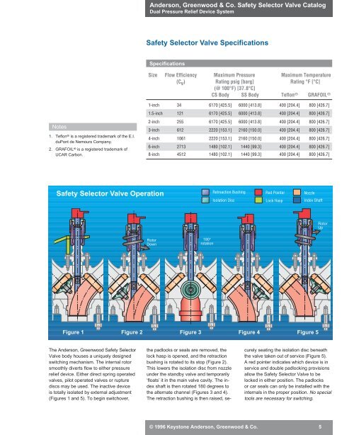
<strong>Safety</strong> <strong>Selector</strong> <strong>Valve</strong> Operation<br />
Retreaction Bushing Red Pointer Nozzle<br />
Isolation Disc Lock Hasp Index Shaft<br />
Rotor<br />
Up<br />
Rotor<br />
Down<br />
180°<br />
rotation<br />
Figure 1 Figure 2 Figure 3 Figure 4 Figure 5<br />
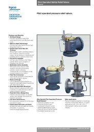
The Anderson, Greenwood <strong>Safety</strong> <strong>Selector</strong><br />
<strong>Valve</strong> body houses a uniquely designed<br />
switching mechanism. The internal rotor<br />
smoothly diverts flow to either pressure<br />
relief device. Either direct spring operated<br />
valves, pilot operated valves or rupture<br />
discs may be used. The inactive device<br />
is totally isolated by external adjustment<br />
(Figures 1 and 5). To begin switchover,<br />
the padlocks or seals are removed, the<br />
lock hasp is opened, and the retraction<br />
bushing is rotated to its stop (Figure 2).<br />
This lowers the isolation disc from nozzle<br />
under the standby valve and temporarily<br />
‘floats’ it in the main valve cavity. The index<br />
shaft is then rotated 180 degrees to<br />
the alternate channel (Figures 3 and 4).<br />
The retraction bushing is then raised, securely<br />
seating the isolation disc beneath<br />
the valve taken out of service (Figure 5).<br />
A red pointer indicates which device is in<br />
service and double padlocking provisions<br />
allow the <strong>Safety</strong> <strong>Selector</strong> <strong>Valve</strong> to be<br />
locked in either position. The padlocks<br />
or car seals can only be installed with the<br />
internals in the proper position. No special<br />
tools are necessary for switching.<br />
© 1996 Keystone Anderson, Greenwood & Co. 5