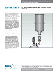
Tyco Crosby Safety Selector Valve datasheet - Askalon
Tyco Crosby Safety Selector Valve datasheet - Askalon
Tyco Crosby Safety Selector Valve datasheet - Askalon

You also want an ePaper? Increase the reach of your titles
YUMPU automatically turns print PDFs into web optimized ePapers that Google loves.
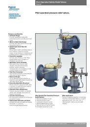
Anderson, Greenwood & Co. <strong>Safety</strong> <strong>Selector</strong> <strong>Valve</strong> Catalog<br />
Dual Pressure Relief Device System<br />
LLOYD'S REGISTER QUALITY COMPANY<br />
ANDERSON, GREENWOOD & CO.<br />
Contents<br />
<strong>Safety</strong> <strong>Selector</strong> <strong>Valve</strong><br />
Product Overview .................................................................................. 1<br />
Features and Benefits ........................................................................... 2<br />
Internal Diagrams .................................................................................. 3<br />
Specifications ........................................................................................ 5<br />
Operation .............................................................................................. 5<br />
Product Overview .................................................................................. 6<br />
Dimensions and Weights ...................................................................... 8<br />
Ordering Information/Options ................................................................ 9<br />
I S O<br />
9 0 0 1<br />
NATIONAL<br />
ACCREDITATION<br />
OF CERTIFICATION<br />
BODIES<br />
<strong>Safety</strong> <strong>Selector</strong> <strong>Valve</strong> Catalog<br />
Revised May 1997<br />
Catalog: SSV-US.96<br />
© 1996 Keystone Anderson, Greenwood & Co. i
Anderson, Greenwood & Co. <strong>Safety</strong> <strong>Selector</strong> <strong>Valve</strong> Catalog<br />
Dual Pressure Relief Device System<br />
<strong>Safety</strong> <strong>Selector</strong> <strong>Valve</strong><br />
Dual Pressure Relief Device<br />
Systems<br />
Anderson, Greenwood & Co. developed<br />
the patented, <strong>Safety</strong> <strong>Selector</strong> <strong>Valve</strong> in<br />
response to the growing demand for<br />
cost-effective, dual pressure relief valve<br />
and/or rupture disc installations in today’s<br />
process industries. The <strong>Safety</strong> <strong>Selector</strong><br />
<strong>Valve</strong> is designed specifically to function<br />
as an effective ‘switchover’ device that<br />
permits routine or emergency servicing of<br />
redundant pressure relief devices with no<br />
process interruption, thus providing continuous<br />
system overpressure protection.<br />
Until recently, bulky and expensive piping<br />
fabrications<br />
or total shutdown were the only methods<br />
for safely servicing the pressure relief<br />
devices. These systems required either<br />
two separate vessel penetrations with mechanically<br />
linked block valves or a 3-way<br />
block valve that commonly resulted in high<br />
inlet pressure loss, excessive turbulence<br />
to the active pressure relief device and<br />
multiple leak points. The Anderson,<br />
Greenwood <strong>Safety</strong> <strong>Selector</strong> <strong>Valve</strong> solves<br />
these problems. It is easy to install, requiring<br />
only one vessel penetration in the<br />
same size as the pressure relief valve inlet.<br />
The unique design provides less than<br />
3% pressure drop to the active pressure<br />
relief valve inlet when used with the<br />
largest API orifice available in a given<br />
valve size, in accordance with API RP520,<br />
Part II and ASME Section VIII guidelines.<br />
Interlocking Block<br />
<strong>Valve</strong> with Two<br />
Vessel Penetrations<br />
3-Way Block <strong>Valve</strong><br />
with Pipe Elbows<br />
Interlocking Block<br />
<strong>Valve</strong> with Pipe Tee<br />
and Elbows<br />
Traditional Dual Pressure Relief Device Systems<br />
© 1996 Keystone Anderson, Greenwood & Co. 1
Anderson, Greenwood & Co. <strong>Safety</strong> <strong>Selector</strong> <strong>Valve</strong> Catalog<br />
Dual Pressure Relief Device System<br />
Features and Benefits<br />
• Provides a safe, efficient method<br />
of switching from an active pressure<br />
relief device to a standby, maintaining<br />
system overpressure protection<br />
regardless of <strong>Safety</strong> <strong>Selector</strong> <strong>Valve</strong><br />
position.<br />
• Provides high C v values, resulting in<br />
less than 3% pressure drop to the active<br />
PRV inlet, when used with the<br />
largest API orifice available in a given<br />
valve size, in accordance with the recommendations<br />
of API RP520 Part II,<br />
Section 2.2 and ASME Section VIII,<br />
Division 1, Appendix M-7. Thereby<br />
greatly reducing the possibility of destructive<br />
chatter of the PRV.<br />
• Requires only one minimally sized<br />
penetration into the vessel or pipe,<br />
reducing costs.<br />
• Greatly reduces field installation costs<br />
and space requirements through preassembled<br />
and compact design.<br />
• Provides process isolation of standby<br />
pressure relief device.<br />
• Allows pressure relief device maintenance<br />
without process shutdown.<br />
• A bleed valve is provided under<br />
each safety relief device as an<br />
effective and safe means of venting<br />
entrapped process under an isolated<br />
pressure relief valve prior to removal<br />
for maintenance.<br />
• Bright red indicator for positive indication<br />
of active pressure relief device.<br />
• Meets all mandatory requirements<br />
of ASME Section VIII, Division 1,<br />
UG-135 (b).<br />
• Foolproof provisions for dual padlocking<br />
in either pressure relief valve<br />
position, in accordance with the recommendations<br />
of ASME Section VIII.<br />
• Packing design has been tested to<br />
ASTM E427, Method A halogen leak<br />
test, reducing probability of fugitive<br />
emissions.<br />
• No seat lapping required for maintenance.<br />
Only recommended spare<br />
parts are soft goods which reduces<br />
cost of ownership.<br />
• Meets standard temperature applications<br />
from cryogenic to +800°F<br />
[427°C].<br />
• Offers materials of construction compatible<br />
with pressure relief devices.<br />
Duplex and 6MO material available.<br />
• Provides reduced number of leak<br />
points to atmosphere, reducing probability<br />
of fugitive emissions.<br />
• Meets construction standards in<br />
accordance with NACE MR-0175.<br />
• Isolates a standby pressure relief<br />
valve in accordance with joint recommendation<br />
of API Subcommittee on<br />
Pressure Relieving Systems and<br />
Subcommittee on Refinery Inspection.<br />
• Type approval by Det Norske Veritas<br />
(DNV).<br />
• Manufactured by an ISO 9001 certified<br />
facility.<br />
• Simplicity of operation with built-in seat<br />
equalization and no special tools minimizes<br />
total time to operate valve at<br />
less than one minute.<br />
Recommended Specifications<br />
• Changeover device inlet connection is<br />
to be the same size and rating as the<br />
pressure relief valve inlets.<br />
• Pressure drop through the changeover<br />
device’s active side cannot exceed 3%<br />
with pressure relief valve fully open.<br />
• Changeover device is to have external<br />
indicator, showing which side is active.<br />
• Provisions for double padlocking in<br />
either position are required.<br />
• A valve bleed port must be located under<br />
each pilot relief valve connection<br />
for pressure venting under the inactive<br />
pressure relief valve.<br />
© 1996 Keystone Anderson, Greenwood & Co. 2
Anderson, Greenwood & Co. <strong>Safety</strong> <strong>Selector</strong> <strong>Valve</strong> Catalog<br />
Dual Pressure Relief Device System<br />
1 1 /2-inch – 8-inch Sizes<br />
Flow<br />
6<br />
5<br />
11<br />
PRD<br />
Connection<br />
Bleed Port for<br />
Standby PRD<br />
10<br />
2<br />
7<br />
1<br />
8<br />
4<br />
3<br />
9<br />
Integral Cast Inlet Flange<br />
(ANSI Raised Face)<br />
Process Connection<br />
12<br />
Materials of Construction<br />
Description<br />
CS<br />
Material<br />
SS<br />
1. Body A216-WCB CS A351-CF8M SS<br />
2. Base A216-WCB CS A351-CF8M SS<br />
3. Isolation Disc 17-4 SS 17-4 SS<br />
4. Rotor A351-CF8M SS A351-CF8M SS<br />
5. Index Shaft 17-4 SS 17-4 SS<br />
6. Indicator A351-CF8M SS A351-CF8M SS<br />
7. Body/Base Nut SA194-2H CS SA194-8M SS<br />
8. Body/Base Stud SA193-B7 CS SA193-8M SS<br />
9. Process Connection Nut SA194-2H CS SA194-8M SS<br />
10. Seat<br />
A479-316 SS or A479-316 SS or<br />
A351-CF8M SS<br />
A351-CF8M SS<br />
11. Retraction Bushing 17-4 SS 17-4 SS<br />
12. Process Connection Stud SA193-B7 CS SA193-8M SS<br />
© 1996 Keystone Anderson, Greenwood & Co. 3
Anderson, Greenwood & Co. <strong>Safety</strong> <strong>Selector</strong> <strong>Valve</strong> Catalog<br />
Dual Pressure Relief Device System<br />
1-inch Size Only<br />
Flow<br />
8 5<br />
6<br />
PRD<br />
Connection<br />
2<br />
Bleed Port for<br />
Standby PRD<br />
1<br />
3<br />
4<br />
10<br />
9<br />
Integral Cast Inlet Flange<br />
(ANSI Raised Face)<br />
Process Connection<br />
7<br />
Materials of Construction<br />
Description<br />
CS<br />
Material<br />
SS<br />
1. Body A216-WCB CS A351-CF8M SS<br />
2. Elbow A216-WCB CS A351-CF8M SS<br />
3. Isolation Disc 17-4 SS 17-4 SS<br />
4. Rotor A351-CF8M SS A351-CF8M SS<br />
5. Index Shaft 17-4 SS 17-4 SS<br />
6. Indicator A351-CF8M SS A351-CF8M SS<br />
7. Seat<br />
A479-316 SS or A479-316 SS or<br />
A351-CF8M SS<br />
A351-CF8M SS<br />
8. Retraction Bushing 17-4 SS 17-4 SS<br />
9. Process Connection Stud SA193-B7 CS SA193-8M SS<br />
10. Process Connection Nut SA194-2H CS SA194-8M SS<br />
© 1996 Keystone Anderson, Greenwood & Co. 4
Anderson, Greenwood & Co. <strong>Safety</strong> <strong>Selector</strong> <strong>Valve</strong> Catalog<br />
Dual Pressure Relief Device System<br />
<strong>Safety</strong> <strong>Selector</strong> <strong>Valve</strong> Specifications<br />
Specifications<br />
Size Flow Efficiency Maximum Pressure Maximum Temperature<br />
(C v ) Rating psig [barg] Rating °F [°C]<br />
(@ 100°F) [37.8°C]<br />
CS Body SS Body Teflon ® GRAFOIL ®<br />
1-inch 34 6170 [425.5] 6000 [413.8] 400 [204.4] 800 [426.7]<br />
1.5-inch 121 6170 [425.5] 6000 [413.8] 400 [204.4] 800 [426.7]<br />
Notes<br />
1. Teflon ® is a registered trademark of the E.I.<br />
duPont de Nemours Company.<br />
2. GRAFOIL ® is a registered trademark of<br />
UCAR Carbon.<br />
2-inch 255 6170 [425.5] 6000 [413.8] 400 [204.4] 800 [426.7]<br />
3-inch 612 2220 [153.1] 2160 [150.0] 400 [204.4] 800 [426.7]<br />
4-inch 1061 2220 [153.1] 2160 [150.0] 400 [204.4] 800 [426.7]<br />
6-inch 2713 1480 [102.1] 1440 [99.3] 400 [204.4] 800 [426.7]<br />
8-inch 4512 1480 [102.1] 1440 [99.3] 400 [204.4] 800 [426.7]<br />
<strong>Safety</strong> <strong>Selector</strong> <strong>Valve</strong> Operation<br />
Retreaction Bushing Red Pointer Nozzle<br />
Isolation Disc Lock Hasp Index Shaft<br />
Rotor<br />
Up<br />
Rotor<br />
Down<br />
180°<br />
rotation<br />
Figure 1 Figure 2 Figure 3 Figure 4 Figure 5<br />
The Anderson, Greenwood <strong>Safety</strong> <strong>Selector</strong><br />
<strong>Valve</strong> body houses a uniquely designed<br />
switching mechanism. The internal rotor<br />
smoothly diverts flow to either pressure<br />
relief device. Either direct spring operated<br />
valves, pilot operated valves or rupture<br />
discs may be used. The inactive device<br />
is totally isolated by external adjustment<br />
(Figures 1 and 5). To begin switchover,<br />
the padlocks or seals are removed, the<br />
lock hasp is opened, and the retraction<br />
bushing is rotated to its stop (Figure 2).<br />
This lowers the isolation disc from nozzle<br />
under the standby valve and temporarily<br />
‘floats’ it in the main valve cavity. The index<br />
shaft is then rotated 180 degrees to<br />
the alternate channel (Figures 3 and 4).<br />
The retraction bushing is then raised, securely<br />
seating the isolation disc beneath<br />
the valve taken out of service (Figure 5).<br />
A red pointer indicates which device is in<br />
service and double padlocking provisions<br />
allow the <strong>Safety</strong> <strong>Selector</strong> <strong>Valve</strong> to be<br />
locked in either position. The padlocks<br />
or car seals can only be installed with the<br />
internals in the proper position. No special<br />
tools are necessary for switching.<br />
© 1996 Keystone Anderson, Greenwood & Co. 5
Anderson, Greenwood & Co. <strong>Safety</strong> <strong>Selector</strong> <strong>Valve</strong> Catalog<br />
Dual Pressure Relief Device System<br />
Tandem <strong>Safety</strong> <strong>Selector</strong> <strong>Valve</strong><br />
Conventional Method<br />
Discharge Header<br />
Anderson Greenwood Tandem<br />
<strong>Safety</strong> <strong>Selector</strong> <strong>Valve</strong><br />
Discharge Header<br />
Outlet <strong>Safety</strong><br />
<strong>Selector</strong> <strong>Valve</strong><br />
Active<br />
Standby<br />
Active<br />
Standby<br />
Inlet <strong>Safety</strong><br />
<strong>Selector</strong> <strong>Valve</strong><br />
Process<br />
Customer Fabricated<br />
Mechanical linkage or Keys and<br />
Locks between block valves<br />
Block <strong>Valve</strong>s<br />
Relief <strong>Valve</strong>s<br />
Process<br />
Anderson, Greenwood Furnished<br />
Interlocking mechanism<br />
Pilot Relief <strong>Valve</strong><br />
Isolation Disc<br />
<strong>Selector</strong> <strong>Valve</strong><br />
© 1996 Keystone Anderson, Greenwood & Co. 6
Anderson, Greenwood & Co. <strong>Safety</strong> <strong>Selector</strong> <strong>Valve</strong> Catalog<br />
Dual Pressure Relief Device System<br />
Tandem <strong>Safety</strong> <strong>Selector</strong> <strong>Valve</strong><br />
Advantages<br />
• Enhanced <strong>Safety</strong>: Eliminates the possibility<br />
of inadvertently closing a block<br />
valve either upstream or downstream<br />
of the intended active pressure relief<br />
valve.<br />
Overpressure protection of process maintained<br />
at all times during switchover.<br />
• Compact and low weight.<br />
• Lower installation costs than with conventional<br />
methods. No field fabrication<br />
or multiple crane lifts required.<br />
The Anderson, Greenwood Tandem<br />
<strong>Safety</strong> <strong>Selector</strong> <strong>Valve</strong> System allows for<br />
simultaneous selection of pressure<br />
relief valve and corresponding discharge<br />
outlet piping of dual pressure relief devices<br />
discharging into a closed header<br />
system.<br />
These redundant pressure relief device<br />
systems can be heavy and bulky, require<br />
significant field fabrication, installation<br />
time and expense, and can be difficult and<br />
confusing to operating personnel.<br />
The Anderson, Greenwood Tandem<br />
<strong>Safety</strong> <strong>Selector</strong> <strong>Valve</strong> System provides a<br />
better, safer alternative.<br />
Redundant pressure relief valves discharging<br />
into a closed header system<br />
utilize all of the inherent advantages of<br />
the Anderson Greenwood <strong>Safety</strong> <strong>Selector</strong><br />
<strong>Valve</strong>s. The two pressure relief valves,<br />
two safety selector valves, and a simple<br />
linkage are pre-assembled at the factory.<br />
Only one flanged inlet and one flanged<br />
outlet connection are required to be made<br />
up in the field. The linkage between the<br />
inlet and outlet pressure relief valves is<br />
simple, foolproof, and provides positive<br />
and simultaneous switching of the<br />
<strong>Selector</strong> <strong>Valve</strong>s.<br />
• Single minimally sized penetration into<br />
vessel, single discharge header connection.<br />
• Anderson, Greenwood & Co. offers a<br />
completely coordinated, tested, and<br />
assembled package consisting of the<br />
pressure relief devices and inlet and<br />
outlet <strong>Safety</strong> <strong>Selector</strong> <strong>Valve</strong>s. The<br />
installed interconnecting linkage ensures<br />
that both inlet and outlet <strong>Safety</strong><br />
<strong>Selector</strong> <strong>Valve</strong>s switch simultaneously.<br />
• Ease of Engineering: No need to use<br />
oversized piping and valves to prevent<br />
excessive pressure loss. <strong>Selector</strong><br />
valves in tandem are of the same line<br />
size as the pressure relief valve<br />
flanges.<br />
• Assurance of less than 3% pressure<br />
drop to the pressure relief valve inlet<br />
when used with the largest API orifice<br />
available in a given valve size.<br />
End your concern about closing off the<br />
wrong outlet block valve. Overpressure<br />
protection is available 100% of the time.<br />
© 1996 Keystone Anderson, Greenwood & Co. 7
Anderson, Greenwood & Co. <strong>Safety</strong> <strong>Selector</strong> <strong>Valve</strong> Catalog<br />
Dual Pressure Relief Device System<br />
Dimensions and Weights<br />
Single Active <strong>Safety</strong> <strong>Selector</strong> <strong>Valve</strong><br />
ANSI Dimensions 1” [25] 1 1 / 2” [40] 2” [50] 3” [80] 4” [100] 6” [150] 8” [200]<br />
Class and Weights<br />
A RF 11.07 [281] 12.07 [307] 11.70 [297] 13.26 [337] 16.13 [410] 20.17 [512] 24.69 [627]<br />
A RTJ 11.07 [281] 12.26 [311] 11.89 [302] 13.45 [342] 16.32 [415] 20.37 [517] 24.88 [632]<br />
150# B 10.31 [262] 10.31 [262] 10.31 [262] 12.00 [305] 14.50 [368] 17.00 [432] 19.50 [495]<br />
D ‘Max.’ 19.50 [495] 19.50 [495] 19.50 [495] 22.44 [570] 26.06 [662] 30.90 [785] 32.44 [824]<br />
Weight 52 (24) 122 (55) 115 (52) 169 (77) 267 (121) 594 (269) 989 (449)<br />
A RF 11.07 [281] 12.45 [316] 11.95 [297] 13.70 [348] 16.63 [442] 21.17 [512] 25.69 [653]<br />
A RTJ 11.07 [281] 12.64 [321] 12.20 [310] 13.95 [354] 16.88 [429] 21.43 [544] 25.94 [659]<br />
300# B 10.31 [262] 10.31 [262] 10.31 [262] 12.00 [305] 14.50 [368] 17.00 [432] 19.50 [495]<br />
D ‘Max.’ 19.50 [495] 19.50 [495] 19.50 [495] 22.44 [570] 26.06 [662] 30.90 [785] 32.44 [824]<br />
Weight 52 (24) 127 (58) 118 (54) 178 (81) 287 (130) 635 (288) 1043 (473)<br />
A RF 11.07 [281] 12.57 [319] 12.21 [310] 14.08 [358] 17.57 [451] 22.36 [568] 26.25 [667]<br />
A RTJ 11.07 [281] 12.57 [319] 12.27 [312] 14.14 [359] 17.63 [488] 22.43 [570] 26.31 [668]<br />
600# B 10.31 [262] 10.31 [262] 10.31 [262] 12.00 [305] 14.50 [368] 17.00 [432] 19.50 [495]<br />
D ‘Max.’ 19.50 [495] 19.50 [495] 19.50 [495] 22.44 [570] 26.06 [662] 30.90 [785] 32.44 [824]<br />
Weight 52 (24) 129 (59) 122 (55) 184 (83) 311 (141) 699 (317) 1127 (511)<br />
A RF 15.00 [381] 13.69 [348] 15.07 [383] 18.26 [464] 21.90 [556] – – – –<br />
A RTJ 15.00 [381] 13.69 [348] 15.07 [383] 18.38 [467] 22.02 [559] – – – –<br />
900# B 12.00 [305] 12.00 [305] 12.00 [305] 12.00 [305] 14.50 [368] – – – –<br />
D ‘Max.’ 21.54 [547] 21.54 [547] 21.54 [547] 22.44 [570] 26.06 [662] – – – –<br />
Weight 153 (70) 155 (70) 174 (79) 235 (107) 381 (173) – – – –<br />
A RF 15.00 [381] 13.69 [348] 15.07 [383] – – – – – – – –<br />
A RTJ 15.00 [381] 13.69 [348] 15.07 [383] – – – – – – – –<br />
1500# B 12.00 [305] 12.00 [305] 12.00 [305] – – – – – – – –<br />
D ‘Max.’ 21.54 [547] 21.54 [547] 21.54 [547] – – – – – – – –<br />
Weight 153 (70) 155 (70) 174 (79) – – – – – – – –<br />
A RF 18.62 [473] 18.60 [472] 15.07 [383] – – – – – – – –<br />
A RTJ 18.62 [473] 18.60 [472] 15.07 [383] – – – – – – – –<br />
2500# B 12.00 [305] 12.00 [305] 12.00 [305] – – – – – – – –<br />
D ‘Max.’ 21.54 [547] 21.54 [547] 21.54 [547] – – – – – – – –<br />
Weight 173 (79) 205 (93) 195 (89) – – – – – – – –<br />
Notes<br />
1. For Tandem assemblies, please consult<br />
factory.<br />
2. Dimensions in inches<br />
[ ] in millimeters.<br />
3. Weights in pounds<br />
( ) in kilograms.<br />
A<br />
D<br />
B<br />
© 1996 Keystone Anderson, Greenwood & Co. 8
Anderson, Greenwood & Co. <strong>Safety</strong> <strong>Selector</strong> <strong>Valve</strong> Catalog<br />
Dual Pressure Relief Device System<br />
Ordering Information<br />
SV R – 08 12 F – C S T O<br />
<strong>Valve</strong> Style<br />
R – Rotary Style Single Active<br />
Connection Size<br />
04 – 1-inch 12 – 3-inch<br />
06 – 1 1 /2-inch 16 – 4-inch<br />
08 – 2-inch 24 – 6-inch<br />
10 – 2 1 /2-inch 32 – 8-inch<br />
Pressure Class<br />
05 – ANSI 150 14 – ANSI 900<br />
10 – ANSI 300 16 – ANSI 1500<br />
12 – ANSI 600 18 – ANSI 2500<br />
Connection Type<br />
F – Raised Face Flange<br />
J – Ring Joint Flange<br />
T – Threaded<br />
X – Special<br />
Body Material<br />
C – CS<br />
S – SS<br />
D – Duplex H – Hastelloy ®<br />
N – Inconel ® M – Monel ®<br />
X – Other (note type on order - consult factory)<br />
Trim Material<br />
S – SS<br />
D – Duplex<br />
H – Hastelloy ® N – Inconel ®<br />
M – Monel ®<br />
X – Other (Consult factory)<br />
Soft Goods<br />
T – Teflon ® 400°F [200°C]<br />
G – GRAFOIL ® 800°F [426°C]<br />
P – PEEK (GRAFOIL ® packing) 600°F [315°C]<br />
X – Special (consult factory)<br />
Options<br />
O – Standard (Inlet <strong>Valve</strong>)<br />
T – Tandem (Outlet <strong>Valve</strong>)<br />
X – Special - note on order required options<br />
Notes<br />
1. Hastelloy ® is a registered trademark of<br />
Haynes International.<br />
2. Inconel ® and Monel ® are registered trademarks<br />
of International Nickel Company.<br />
© 1996 Keystone Anderson, Greenwood & Co. 9
<strong>Safety</strong> <strong>Selector</strong> <strong>Valve</strong> Catalog<br />
Revised May 1997<br />
Catalog: SSV-US.96<br />
Anderson, Greenwood & Co.<br />
A Subsidiary of Keystone International, Inc.<br />
P.O. Box 944<br />
Stafford, Texas 77497, USA<br />
Tel: (281) 274-4400<br />
Fax: (281) 240-1800<br />
International Tel: +1 281 274-4400<br />
International Fax: +1 281 240-1800<br />
http:/ /www.industry.net/anderson.greenwood<br />
Keystone Anderson, Greenwood<br />
Corrie Way, Bredbury Industrial Estate,<br />
Stockport, Cheshire SK6 2ST, UK<br />
Tel: 0161 494 5363<br />
Fax: 0161 494 5672<br />
Telex: 668379<br />
International Tel: +44 161 494 5363<br />
International Fax: +44 161 494 5672<br />
© 1996 Keystone Anderson, Greenwood & Co. Printed in USA
<strong>Safety</strong> <strong>Selector</strong> <strong>Valve</strong> Catalog<br />
Dual Pressure Relief Device System<br />
ANDERSON, GREENWOOD & CO.<br />
A Keystone Company