Tyco Fig.110-190 ball valves datasheet - Askalon
Tyco Fig.110-190 ball valves datasheet - Askalon
Tyco Fig.110-190 ball valves datasheet - Askalon

Create successful ePaper yourself
Turn your PDF publications into a flip-book with our unique Google optimized e-Paper software.
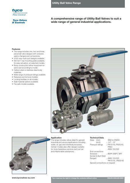
Utility Ball Valve RangeA comprehensive range of Utility Ball Valves to suit awide range of general industrial applications.Features• The range includes one, two and threepiece <strong>ball</strong> valve designs with screwed,weld or flanged end connections.• 3/4/5-way multi-port designs available.• ISO 5211 top mounting plate available,for easy actuation, on selected models.• Body construction either investment orsand cast according to model.• Carbon steel or stainless steel bodymaterials.• Wide range of pressure ratings available.• Reduced and full bore models.• Locking facilities on all models.• Seat material options available.• Fire safe models available.ApplicationThe range includes <strong>valves</strong> ideal for generalindustrial and service applications includingwater, oil, gas and chemical processes.Certain models also offer designs suitablefor more hazardous services such as fueland inflammable substances.Technical DataSizes (mm) DN8 to DN300(inch) : 1/4” - 12”Pressure ratings : PN10/16, PN25/40,PN63ANSI 150/300End connectionsScrewed: BSPP, BSPT, NPTSocket & Butt WeldFlanged : ANSI 150/300PN10/16, PN25/40Special connections on requestwww.tyco<strong>valves</strong>-eu.com<strong>Tyco</strong> reserves the right to change the contents without noticeHDLDS-0009-EN-0503
Utility Ball Valve RangeF110 - One-piece body <strong>ball</strong> valve See page 4• An economical, investment cast, one-piece body <strong>ball</strong> valve in stainless steelSize rangeDN8 (1/4”) to DN50 (2”)- Reduced BoreF120 - Two-piece body <strong>ball</strong> valve See page 5• General purpose, 1000 psi (PN63) <strong>ball</strong> valve, in stainless steelSize rangeDN8 (1/4”) to DN50 (2”)- Full BoreF130M - Three-way split body <strong>ball</strong> valve See page 6/7• With ISO 5211 top mounting plate and fully enclosed bolting• Flanged ANSI 150, 300 or DIN PN 10/16, 25/40• L-, T- or LL-port options, 90° operation• Carbon steel or stainless steel bodiesSize rangeDN50 (2”) to DN150 (6”)- Full BoreF133M - Three and four-way split body <strong>ball</strong> valve See page 8/10• With ISO 5211 top mounting plate and fully enclosed bolting• End connections screwed, socket weld, butt weld or flanged• Flanged ANSI 150, 300 or DIN PN 10/16, 25/40• L-, T- or LL-port options, 90° operation• Carbon steel or stainless steel bodiesSize rangeDN10 (3/8”) to DN50 (2”)- Full and Reduced BoreF138 - Three way multi-port <strong>ball</strong> valve See page 11• With ISO 5211 top mounting plate• Investment stainless steel cast body• Screwed ends, NPT, BSPP, BSPT reduced bore• L- or T-port options, 90° operationSize rangeDN8 (1/4”) to DN50 (2”)- Reduced Bore<strong>Tyco</strong> reserves the right to change the contents without notice page 2
Utility Ball Valve RangeF150 - Three-piece economical <strong>ball</strong> valve See page 12• Three piece, swing-out design• End connections screwed, butt weld or socket weld• Carbon steel or stainless steel bodiesSize rangeDN8 (1/4”) to DN100 (4”)- Full BoreF170 - Three-piece <strong>ball</strong> valve to ISO 5211 See page 13/14• With ISO 5211 top mounting plate• End connections flanged, screwed, butt weld or socket weld• Carbon steel or stainless steel bodiesSize rangeDN8 (1/4”) to DN100 (4”)- Full BoreF180/F180F - Three-piece heavy duty <strong>ball</strong> valve See page 15/18• With ISO 5211 top mounting plate and fully enclosed bolting• End connections screwed, butt weld or socket weld• Carbon steel or stainless steel bodies• F180F Fire safe tested to API 607Size rangeF180 - DN8 (1/4”) to DN100 (4”)F180F - DN10 (3/8”) to DN80 (3”)- Full Bore and Reduced BoreF<strong>190</strong>/F<strong>190</strong>F - Split body flanged <strong>ball</strong> valve See page 19/23• With ISO 5211 top mounting pad• Flanged ANSI 150, 300 or DIN PN10/16, 25/40• Investment casting for 4” and under, carbon steel or stainless steel bodies• F<strong>190</strong>F Fire safe tested to API 607Size rangeDN15 (1/2”) to DN300 (12”)- Full Bore<strong>Tyco</strong> reserves the right to change the contents without notice page 3
Utility Ball Valve RangeF110 - One-piece body <strong>ball</strong> <strong>valves</strong>Materials of constructionNo. Part Name Material Quantity1 Body CF8M / 1.4408 12 Insert ASTM A351 Gr CF8M 13 Ball ASTM A351 Gr CF8M 14 Seat PTFE 25 Anti-static Stem A276 Type 316 16 Handle SUS304 17 Stem Packing PTFE 18 Thrust Washer PTFE 19 Gland Ring SUS304 110 Handle Sleeve Vinyl 111 Handle Washer SUS304 112 Stem Nut SUS304 113 Locking Device SUS304 1Features• General purpose 1000psi (PN63) <strong>ball</strong> valve• Investment cast, one piece body• Stainless steel construction only• Screwed ends to: BSPPBSPTNPT• Blow-out proof stem• Locking device• Size range DN8 (1/4”) to DN50 (2”)- Reduced boreDimensions (mm)Size DN Ød G H L B1 B2 W (kg)1/4" 8 5.0 72 34 39.0 7.0 11.0 0.073/8" 10 7.0 83 36 44.0 8.0 11.0 0.111/2" 15 9.0 85 42 57.0 14.0 15.0 0.183/4" 20 12.5 85 44 60.0 10.7 15.0 0.251" 25 16.0 105 48 71.0 17.0 17.4 0.431 1/4" 32 20.0 105 52 78.0 16.7 19.0 0.701 1/2" 40 25.0 123 60 83.0 16.6 19.0 0.822" 50 32.0 123 60 100.0 19.7 22.5 1.30Pressure/temperature chartPRESSURE IN PSIPTFEPRESSURE IN BARTEMPERATURE IN °F (°C)<strong>Tyco</strong> reserves the right to change the contents without notice page 4
Utility Ball Valve RangeF120 - Two-piece body <strong>ball</strong> <strong>valves</strong>Features• General purpose 1000 psi (PN63), <strong>ball</strong> valve• Two piece, investment cast body• Stainless steel construction only• Screwed end to: BSPPBSPTNPT• DIN 3202 M3 face-to-face• Adjustable stem packing• Locking device• Size range DN8 (1/4”) to DN50 (2”)- Full boreMaterials of constructionNo. Part Name Material Quantity1 Body CF8M / 1.4408 12 Ball ASTM A351 Gr. CF8M 13 Seat PTFE 24 Body Seal PTFE 15 Cap CF8M / 1.4408 16 Anti-Static Stem A276 Type 316 17 Thrust Washer PTFE 28 Stem Packing PTFE 19 Gland Nut SUS304 110 Stem Washer SUS304 111 Stem Nut SUS304 112 Handle SUS304 113 Handle Sleeve Vinyl 114 Locking Device SUS304 1Dimensions (mm)Size DN Ød G H L B W (kg)1/4" 8 11.2 108 52 50 10.0 0.243/8" 10 11.2 108 54 60 10.0 0.281/2" 15 15.0 136 62 75 13.0 0.443/4" 20 20.0 150 65 80 16.0 0.561" 25 25.0 168 80 90 17.0 0.881 1/4" 32 32.0 168 85 110 20.0 1.441 1/2" 40 38.0 195 95 120 22.0 1.942" 50 50.0 195 110 140 25.0 3.36Pressure/temperature chartPRESSURE IN PSIPTFEPRESSURE IN BARTEMPERATURE IN °F (°C)<strong>Tyco</strong> reserves the right to change the contents without notice page 5
Utility Ball Valve RangeF130M - Three-way split body <strong>ball</strong> <strong>valves</strong>Materials of constructionNo. Part Name Material Quantity1 Body CF8M / WCB, 1.4408 / 1.0619 12 Cap CF8M / WCB, 1.4408 / 1.0619 43 Ball ASTM A351 Gr. CF8M 14 Ball Seat RPTFE 45 Body Gasket PTFE 46 Bolt Nut A2-70 *7 Bolt A2-70/8.8 *8 Bushing 25% Carbon Filled PTFE 19 Anti-Static Stem A276 Type 316 110 Lower Thrust Washer 50% S.S Powder / 50% PTFE 111 Compress Ring SUS316 112 Upper Thrust Washer TFM1600 113 Cover CF8M / WCB, 1.4408 / 1.0619 114 V-Ring Stem Packing PTFE 1 Set15 Thrust Washer 50% S.S Powder / 50% PTFE 116 Gland SUS304 117 Stop Bolt A2-70 118 Cover Seal PTFE 119 Belleville Washer SUS301 220 Triangle Stopper SUS304 121 Lock Saddle SUS304 122 Stem Nut SUS304 123 Stem Adapter CF8 124 Handle Steel 125 Block Cover ASTM A351 Gr. CF8M / ASTM A216 Gr. WCB 1*Features• Four <strong>ball</strong> seats• Simplicity in replacing valve seats andpacking• Investment cast body DN50 (2”) toDN100 (4”)• Sand casting DN150 (6”)• Standard L-port and T-port; optional LLportfor 4 way• Tightness to ISO 5208 Cat. A• Patented “SEALMASTER” stemarrangement• Double stem sealing complies with TA-Luftrequirements• Trunnion mounted• Lower operation torque• ISO 5211 mounting plate• Full bore and flanged connection• Anti-static design• Optional <strong>ball</strong> and body patterns for variousflow paths• Valve pressure rating:ANSI Class 150/300DIN PN 10/16/25/40• 2" - 3" Class 150, Class 300, PN10/16, PN25/40, All Standards: 20pcs• 4" Class 150, Class 300, PN10/16, PN25/40, All Standards: 28pcs• 6" Class 150, Class 300, PN10/16, PN25/40, All Standards: 56pcs* For No 25 Block cover, please refer to page 7Ball Port ConfigurationPressure/temperature chartTop viewSide EntryTee-Port(T)Side EntryAnglePort(L)Side EntryDoubleAnglePort(LL)Side EntryStraight Port(S)PRESSURE IN PSIANSI 300PN 25/40ANSI 150PN 10/16RPTFEPRESSURE IN BARSide viewTEMPERATURE IN °F (°C)<strong>Tyco</strong> reserves the right to change the contents without notice page 6
Utility Ball Valve RangeF130M - Three-way split body <strong>ball</strong> <strong>valves</strong>25Dimensions (mm)Size DN A B ØP G W2" 50 23.5 14.0 70 9.5 M82 1/2" 65 41.5 22.4 102 17 M123" 80 41.5 19.0 102 17 M124" 100 47.5 25.9 102 17 M126" 150 65.0 37.0 125 23 M12Size DN Ød ØB ØC ØD TANSI ANSI PN PN ANSI 150 PN PN ANSI ANSI PN PN ANSI ANSI PN PN150 300 10/16 25/40 ANSI 300 10/16 25/40 150 300 10/16 25/40 150 300 10/16 25/402" 50 50 120.5 127 125 125 92 102 102 152 165 165 165 15.9 22.3 20 202 1/2" 65 65 139.5 149 145 145 105 122 122 178 <strong>190</strong> 185 185 17.5 25.4 18 223" 80 76 152.5 168 160 160 127 138 138 <strong>190</strong> 210 200 200 19.1 28.6 20 244" 100 100 <strong>190</strong>.5 200 180 <strong>190</strong> 157 158 162 229 254 220 235 23.9 31.8 20 246" 150 150 241.3 269.9 240 250 216 212 218 279.4 317.5 285 300 25.4 36.6 22 28Size DN f N ØN L H H1 MANSI 150 PN PN ANSI ANSI PN PN ANSI ANSI PN PN ANSI ANSI PN PNANSI 300 10/16 25/40 150 300 10/16 25/40 150 300 10/16 25/40 150 300 10/16 25/402" 50 1.6 3 4 8 4 4 19 19 18 18 220 220 230 230 80 136.5 4002 1/2" 65 1.6 3 4 8 4 8 19 22 18 18 280 280 290 290 97 162 5003" 80 1.6 3 4 8 8 8 19 22 18 18 285 285 310 310 108 186 5004" 100 1.6 3 8 8 8 8 19 22 18 22 347 347 350 350 129 213 6506" 150 1.6 3 8 12 8 8 22.2 22.2 22 26 480 550 480 550 215 280 800<strong>Tyco</strong> reserves the right to change the contents without notice page 7
Utility Ball Valve RangeF133M - Three- and four-way split body <strong>ball</strong> <strong>valves</strong>Handle for valveSize DN 40 (1 1/2”)Materials of constructionNo. Part Name Material Quantity1 Body CF8M / WCB, 1.4408 / 1.0619 12 Cap CF8M / WCB, 1.4408 / 1.0619 43 Ball ASTM A351 Gr. CF8M 14 Ball Seat RPTFE 45 Body Gasket PTFE 46 Bolt Washer SUS304 167 Bolt A2-70 168 Lower Thrust Washer 50% S.S Powder / 50% PTFE 19 Compress Ring SUS316 110 Upper Thrust Washer TFM1600 111 V-Ring Stem Packing PTFE 1 Set12 Thrust Washer 50% S.S Powder / 50% PTFE 113 Anti-Static Stem A276 Type 316 114 Gland SUS304 115 Belleville Washer SUS301 216 Stem Nut SUS304 1-217 Handle SUS304 118 Handle Sleeve Vinyl 119 Rivet SUS304 220 Stem Adapter CF8 121 Triangle Stopper SUS304 122 Lock Saddle SUS304 123 Locking Trigger SUS304 124 Fix Plate SUS304 125 Stop Bolt A2-70 1Features• Four <strong>ball</strong> seats• Simplicity in replacing valve seats andpacking• Investment casting for body and end cap• Optional LL-port for 4 way• Patented “SEALMASTER” stemarrangement• Double stem sealing complies with TA-Luftrequirements• Lower operation torque• ISO 5211 mounting plate• Anti-static design• Optional <strong>ball</strong> & body patterns for variousflow paths• Size range, DN10 (3/8”) to DN50 (2”) -Full and reduced bore• Valve pressure rating:ANSI Class 150/300DIN PN 10/16/25/40• End connections screwed, buttweld, socket weld and flanged• Flanged connection in full bore only• 3/8" - 1 1/4" For standard handle• 1 1/2" T-handleBall Port ConfigurationBall Port ConfigurationSide EntryTee-Port(T)Side EntryAnglePort(L)Side EntryDoubleAnglePort(LL)Side EntryStraight Port(S)Side Entry3-wayASide Entry4-wayBTop viewTop viewSide viewSide view<strong>Tyco</strong> reserves the right to change the contents without notice page 8
Utility Ball Valve RangeF133M - Three- and four-way split body <strong>ball</strong> <strong>valves</strong> - threaded endsFull bore DN 40 (1 1/2”)Reduced bore DN 50 (2”)Pressure/temperature chartPRESSURE IN PSIRPTFEPRESSURE IN BARTEMPERATURE IN °F (°C)Dimensions (mm)Size DN Ød H L M A B G ØP ØF WF R F R3/8" 1/2” 10 15 12 63.5 90 115 12.5 5.5 6.3 42 12 M51/2" 3/4” 15 20 15 82 107 130 18.0 11.2 6.3 42 12 M53/4" 1” 20 25 20 86 110.5 130 17.5 11.5 8.0 50 14 M61" 1 1/4” 25 32 25 98 126.5 165 20.0 12 8.0 50 14 M61 1/4" 1 1/2” 32 40 32 100 135 200 23.5 14 9.5 70 16 M81 1/2" 2” 40 50 38 127 154 400 23.5 14 9.5 70 16 M8F: Full boreR: Reduced bore<strong>Tyco</strong> reserves the right to change the contents without notice page 9
Utility Ball Valve RangeF133M - Three- and four-way split body <strong>ball</strong> <strong>valves</strong> - flanged endsSize DN 40 (1 1/2”)Pressure/Temperature chartPRESSURE IN PSIANSI 300PN 25/40ANSI 150RPTFEPRESSURE IN BARPN 10/16TEMPERATURE IN °F (°C)DimensionsSize DN A B ØC ØD Ød ØE ØP N M WANSI 150 PN ANSI ANSI PN ANSI ANSI PNANSI 300 10/40 150 300 10/40 150 300 10/401/2" 15 18 11.2 35 45 89 95 95 15 42 60.5 66.5 65 4 130 M53/4" 20 17.5 11.5 43 58 98 117 105 20 50 70 82.5 75 4 130 M61" 25 20 12 51 68 108 124 115 25 50 79.5 89 85 4 165 M61 1/2" 40 23.5 14 73 88 127 156 150 38 70 98.5 114.5 110 4 400 M8Size DN F G H L T f ØnPN ANSI ANSI PN ANSI 150 PN ANSI ANSI PN10/40 150 300 10/40 ANSI 300 10/40 150 300 10/401/2" 15 12 6.3 82 157.8 11.2 14.3 16 1.6 2 16 16 143/4" 20 14 8 86 167.8 11.2 15.9 18 1.6 2 16 19 141" 25 14 8 98 182 11.2 17.5 18 1.6 2 16 19 141 1/2" 40 16 9.5 127 218 14.2 20.7 18 1.6 3 16 22 18<strong>Tyco</strong> reserves the right to change the contents without notice page 10
Utility Ball Valve RangeF138 - Three- way multi port <strong>ball</strong>-<strong>valves</strong> - threaded endsDetail GFeatures• General purpose 1000 psi (PN63), <strong>ball</strong> valve• Three way multi-port <strong>ball</strong> valve with L-portor T-port options, 90° operation• Investment cast body• Stainless steel body, RPTFE seats• Screwed ends to: BSPPBSPTNPT• ISO 5211 top mounting plate• Blow-out proof stem• Size range DN8 (1/4”) to DN50 (2”) -Reduced boreBall Port ConfigurationTop viewSide EntryTee-Port(T)Side EntryAngle Port(L)Materials of constructionNo. Part Name Material Quantity1 Body CF8M / 1.4408 12 Cap CF8M / 1.4408 23 Seat RPTFE 44 Ball ASTM A351 Gr. CF8M 15 Anti-Static Stem A276 Type 316 16 Joint Gasket PTFE 27 Thrust Washer PTFE 18 Gland SUS304 19 Handle SUS304 110 Handle Washer SUS304 1-311 Washer SUS304 112 Handle Nut SUS304 113 Handle Sleeve Vinyl 114 End Cap CF8M / 1.4408 115 Stem Packings PTFE 1 Set16 End Cap Seal PTFE 117 Gland Washer SUS304 118 Bolt A2-70 119 Locking Device SUS304 1Side viewPressure/Temperature chartDetail KPRESSURE IN PSIRPTFETEMPERATURE IN °F (°C)PRESSURE IN BARDimensions (mm)Size DN A B ØC D E F ØP N Ød±0.5 L±0.8 H±3.0 M±3.0 Wt(kg)1/4" 8 11 6 12 9 29.7 34.6 42 M5*0.8 11.0 69 58 124 0.603/8" 10 11 6 12 9 29.7 34.6 42 M5*0.8 11.0 69 58 124 0.601/2" 15 11 6 12 9 29.7 40.8 42 M5*0.8 12.7 75 51 124 0.673/4" 20 13 6 15 11 35.4 45.0 50 M6*1.0 16.0 86 71 168 1.201" 25 19 7.5 15 11 35.4 52.3 50 M6*1.0 20.0 101 70 168 1.701 1/4" 32 19 7.5 15 11 35.4 58.0 50 M6*1.0 25.0 118 88 198 2.401 1/2" 40 23.5 8.5 15 11 49.5 63.0 70 M8*1.25 32.0 125 100 194 3.352" 50 24.5 8.5 18.5 14 49.5 75.5 70 M8*1.25 38.1 149 110 215 5.50<strong>Tyco</strong> reserves the right to change the contents without notice page 11
Utility Ball Valve RangeF150 - Three-piece economical <strong>ball</strong> <strong>valves</strong>Materials of constructionNo. Part Name Material Quantity1 Body CF8M / WCB, 1.4408 / 1.0619 12 Body Seat PTFE 23 Body Gasket PTFE 24 Ball ASTM A351 Gr. CF8M 15 Bolt Nut A2-70 4-66 Bolt Washer SUS304 4-67 Bolt A2-70 4-68 Cap CF8M / WCB, 1.4408 / 1.0619 2*9 Anti-Static Stem A276 Type 316 110 Handle Washer SUS304 111 Stem Packing PTFE 112 Thrust Washer PTFE 113 Gland Nut SUS304 114 Stem Nut SUS304 115 Handle SUS304 116 Handle Sleeve Vinyl 117 Locking Device SUS304 1Features• General purpose 1000 psi (PN63) / 600 psi(PN40), <strong>ball</strong> valve• Three piece, swing out design• Investment casting for body and end cap• End connections screwed, butt weld andsocket weld• Blow-out proof stem• Locking device• Size range DN8 (1/4”) to DN100 (4”) -Full bore* Stainless steel welded connectors are CF3M/1.4409Pressure/Temperature chartThreadedendSocket WeldendButtweldend1/4"(DN8) - 1 1 /2"(DN40)Dimensions (mm)Size DN Ød L H M ØN2 ØN3 ØM3 Wt(kg)1/4" 8 11.6 60 52 108 14.1 9.4 18.0 0.383/8" 10 12.7 60 52 108 18.0 12.7 18.0 0.381/2" 15 15.0 75 57 108 22.0 16.1 22.7 0.583/4" 20 20.0 78 59 132 27.3 21.4 27.5 0.761" 25 25.0 85 71 153 34.0 27.2 34.0 1.101 1/4" 32 32.0 104 78 153 42.8 35.5 42.7 2.151 1/2" 40 38.0 120 91 195 48.9 41.2 48.6 2.302" 50 50.0 130 91 195 61.4 52.7 60.5 3.402 1/2" 65 63.0 165 131 265 77.0 66.0 76.4 7.803" 80 78.0 182 140 265 90.0 81.0 92.0 11.204" 100 97.0 230 175 285 115.7 107.5 119.5 22.50PRESSURE IN PSI2"(DN50) - 4"(DN100)PTFETEMPERATURE IN °F (°C)PRESSURE IN BARØN1: BSPP, BSPT, NPT<strong>Tyco</strong> reserves the right to change the contents without notice page 12
Utility Ball Valve RangeF170 - Three-piece <strong>ball</strong> <strong>valves</strong> to ISO 52112122232019181211109161413171615873245Sizes DN8-DN80 (1/4”-3”)42Handle for valveSize DN 100 (4”)Features• Three-piece swing out design• ISO 5211 top mounting plate• End connections flanged, screwed, buttweld or socket weld• Carbon steel or stainless steel bodies• Size range DN15 (1/2”) to DN100 (4”) -Full bore• Double stem sealing arrangement• Primary level with patentedSEALMASTER.• Seat material options• Antistatic design• Tightness to EN 12266-1, rate APRESSURE IN PSIPressure/Temperature chart1/4"(DN8) - 1 1 /2"(DN40)2"(DN50) - 4"(DN100)PTFEPRESSURE IN BARMaterials of constructionNo. Part Name Material Quantity1 Body CF8M / WCB, 1.4408 / 1.0619 12 Cap CF8M / WCB, 1.4408 / 1.0619 2*3 Ball ASTM A351 Gr. CF8M 14 Bolt A2-70 4-65 Bolt Washer SUS304 / S45C 4-66 Body Gasket PTFE 27 Ball Seat PTFE 28 Anti-Static Stem A276 Type 316 19 V-Ring Stem Packing PTFE 1 Set10 Thrust Washer 50% S.S Powder / 50% PTFE 111 Gland SUS304 112 Belleville Washer SUS301 / WCB1075 213 Locking Trigger SUS304 114 Fix Plate SUS304 115 Lower Stem Seal 50% S.S Powder / 50% PTFE 116 Compress Ring SUS316 117 Upper Stem Seal TFM1600 118 Stop Bolt A2-70 119 Lock Saddle SUS304 120 Stem Nut SUS304 221 Handle CF8 / Steel 122 Handle Sleeve Vinyl 123 Rivet SUS304 224 Bolt Nut A2-70 4-1225 Triangle Stopper SUS304 126 Handle Adapter CF8 1* Stainless steel welded connectors are CF3M/1.4409TEMPERATURE IN °F (°C)<strong>Tyco</strong> reserves the right to change the contents without notice page 13
Utility Ball Valve RangeF170 - Three-piece <strong>ball</strong> <strong>valves</strong> to ISO 5211Threaded end Socket weld Butt weld Flange end (PN25/40 F1)TDimensions (mm)Wt(kg)Size DN A B G ØP ØF W ThreadedSW, BW1/4" 8 12.5 6.0 5.0 36.0 7.9 M5 0.443/8" 10 12.5 6.0 5.0 36.0 7.9 M5 0.441/2" 15 17.0 9.0 6.3 42.0 9.7 M5 0.443/4" 20 17.5 9.0 6.3 42.0 9.7 M5 0.951" 25 20.4 12.3 8.0 50.0 11.2 M6 1.401 1/4" 32 20.4 12.3 8.0 50.0 11.2 M6 1.901 1/2" 40 24.0 13.8 9.5 70.0 16 M8 3.082" 50 24.0 13.8 9.5 70.0 16 M8 4.702 1/2" 65 42.0 28.0 15.0 102.0 19 M10 8.903" 80 42.0 28.0 15.0 102.0 19 M10 14.14" 100 48.0 29.0 17.0 102.0 29 M10 22PN25/40Size DN Ød M H L1 L2 Q t1 T ØU ØX ØY ØZ ØN2 ØN3 Flange1/4" 8 11.6 135.0 65.5 65.5 N/A N/A 0.8 N/A N/A N/A N/A N/A 14.2 11.6 N/A3/8" 10 12.7 135.0 66.0 65.5 N/A N/A 0.8 N/A N/A N/A N/A N/A 17.5 12.5 N/A1/2" 15 15.0 135.0 83.0 71.9 130.0 4.0 0.8 16.0 14.0 95.0 65.0 45.0 21.7 15.8 2.243/4" 20 20.0 135.0 86.0 85.0 150.0 4.0 1.0 18.0 14.0 105.0 75.0 58.0 27.1 21.0 3.041" 25 25.0 165.0 96.0 91.96 160.0 4.0 1.6 18.0 14.0 115.0 85.0 68.0 33.8 26.6 3.9011/4" 32 32.0 165.0 102.0 110.0 180.0 4.0 1.8 18.0 18.0 140.0 100.0 78.0 42.6 35.1 6.2511/2" 40 38.0 200.0 115.0 123.0 200.0 4.0 1.8 18.0 18.0 150.0 110.0 88.0 48.6 40.9 7.152" 50 50.8 200.0 124.0 142.0 230.0 4.0 1.8 20.0 18.0 165.0 125.0 102.0 61.1 52.5 10.1521/2" 65 65.2 250.0 160.0 173.9 290.0 8.0 2.0 22.0 18.0 185.0 145.0 122.0 77.1 68.9 16.623" 80 76.2 250.0 170.0 193.0 310.0 8.0 2.0 24.0 18.0 200.0 160.0 138.0 90.2 77.9 23.804" 100 97.4 500.0 182.0 221.4 350.0 8.0 2.0 24.0 22.0 235.0 <strong>190</strong>.0 162.0 115.1 102.3 35.60ØN1: BSPP, BSPT, NPTN/A = Not Available<strong>Tyco</strong> reserves the right to change the contents without notice page 14
Utility Ball Valve RangeF180 - Three-piece heavy duty <strong>ball</strong> <strong>valves</strong>21 22 232019181211109814131716157632 41 5 24Sizes DN8-DN80 (1/4”-3”)Handle for valveSize DN 100 (4”)Features• Heavy duty, three piece <strong>ball</strong> valve• Patented “SEALMASTER” stemarrangement• Double stem sealing complies with TA-Luftrequirements• ISO 5211 top mounting plate• Blow out proof stem and antistatic design• Fully enclosed bolting for sizes up to DN40full bore• End connections, screwed, butt weld andsocket weld• Carbon steel and stainless steel bodies• Tightness to EN 12266-1, rate A• Seat material options• Optional castings per AD/WO/TRD-100 areavailable• Size range DN8 (1/4”) to DN100 (4”) -Full and reduced boreMaterials of constructionNo. Part Name Material Quantity1 Body CF8M / WCB, 1.4408 / 1.0619 12 Cap CF8M / WCB, 1.4408 / 1.0619 2*3 Ball ASTM A351 Gr. CF8M 14 Bolt A2-70 4-65 Bolt Washer SUS304 / S45C 4-66 Ball Seat RPTFE 27 Body Gasket PTFE 28 Anti-Static Stem A276 Type 316 19 V-Ring Stem Packing PTFE 1 Set10 Thrust Washer 50% S.S Powder / 50% PTFE 111 Gland SUS304 112 Belleville Washer SUS301 / 1075 213 Locking Trigger SUS304 114 Fix Plate SUS304 115 Lower Stem Seal 50% S.S Powder / 50% PTFE 116 Compress Ring SUS316 117 Upper Stem Seal TFM1600 118 Stop Bolt A2-70 119 Lock Saddle SUS304 120 Stem Nut SUS304 221 Handle CF8 / Steel 122 Handle Sleeve Vinyl 123 Rivet SUS304 224 Bolt Nut A2-70 4-1225 Triangle Stopper SUS304 126 Handle Adapter ASTM A351 Gr. CF8 1* Stainless steel welded connectors are CF 3M/1.4409Pressure/Temperature charts1/4"(DN8) ~1"(DN25)1/2"(DN15R)~ 1 1 /4"(DN32R)PRESSURE IN PSI1 1 /4"(DN32) ~ 2"(DN50)2 1 /2"(DN65)~ 3"(DN80)RPTFEPRESSURE IN BARPRESSURE IN PSI1 1 /2"(DN40R) ~ 2 1 /2"(DN65R)3"(DN80R)~ 4"(DN100R)PRESSURE IN BARRPTFETEMPERATURE IN °F (°C)Full Bore SizesTEMPERATURE IN °F (°C)Reduced Bore Sizes<strong>Tyco</strong> reserves the right to change the contents without notice page 15
Utility Ball Valve RangeF180 - Three-piece heavy duty <strong>ball</strong> <strong>valves</strong>Side viewFull bore:DN10 (3/8”)Reduced bore:DN15 (1/2”)Side viewFull bore:DN15-DN40 (1/2”-1 1/2”)Reduced bore:DN20-DN50 (3/4”-2”)Side viewFull bore:DN50-DN80 (2”-3”)Reduced bore:DN65-DN100 (2 1/2”-4”)ThreadedendSocketweldButt weldSCH#5(FP)/SCH#10(FP)NW(RP)/RJT(RP)Full Bore Dimensions (mm)Size DN Ød A B G ØP ØF W M t1 t2 L1 L2 L3 ØN2 ØN3 ØN4 H Wt(kg)5S 10S1/4" 8 11.2 12.7 5.6 5.0 36 7.9 M5 115 0.5 N/A N/A 66.6 21.2 N/A 14.1 10.2 N/A 66 0.623/8" 10 12.7 12.7 5.6 5.0 36 7.9 M5 115 0.5 N/A N/A 66.6 21.2 N/A 17.5 13.5 N/A 66 0.601/2" 15 15.0 18.0 9.0 6.3 42 9.7 M5 135 0.5 1.65 2.1 71.6 25.2 129.8 22.4 16.8 21.7 84 0.823/4" 20 20.0 17.5 9.0 6.3 42 9.7 M5 135 0.5 1.65 2.1 96.6 32.3 140.9 27.4 22.0 27.2 88 1.421" 25 25.0 20.0 12.0 8.0 50 11.2 M6 165 0.5 1.65 2.1 109.0 42.3 223.3 34.2 27.6 34.0 98 2.021 1/4" 32 31.8 20.0 12.0 8.0 50 11.2 M6 165 0.5 1.65 2.8 117.0 49.4 230.4 43.0 36.1 42.7 101 2.761 1/2" 40 38.1 23.5 14.0 9.5 70 16.0 M8 200 0.5 1.65 2.8 129.0 57.2 240.2 49.0 41.9 48.6 117 4.122" 50 50.8 23.5 14.0 9.5 70 16.0 M8 200 1.0 1.65 2.8 142.0 71.4 259.4 61.1 54.5 60.5 125 6.002 1/2" 65 65.0 41.5 24.7 17.0 102 22.2 M10 250 1.0 N/A N/A 174.0 89.0 N/A 77.1 70.9 N/A 164 9.483" 80 80.0 38.5 25.7 17.0 102 22.2 M10 250 1.6 N/A N/A 193.0 108.5 N/A 90.2 81.1 N/A 173 15.64ØN1: BSPP, BSPT, NPTN/A = Not AvailableReduced Bore Dimensions (mm)Size DN Ød A B G ØP ØF W M t1 t3 L1 L2 L4 ØN2 ØN3 H ØR Wt(kg)NW RJT NW RJT1/2" 15 12.7 12.7 5.6 5.0 36 7.9 M5 115 0.5 1.5 1.6 66.6 21.2 136 22.4 16.8 66 18 12.7 0.633/4" 20 15.0 18.0 9.0 6.3 42 9.7 M5 135 0.5 1.5 1.55 71.6 25.2 133 27.4 22.0 82 22 19.0 0.851" 25 20.0 17.5 9.0 6.3 42 9.7 M5 135 0.5 1.5 1.6 96.6 32.3 151 34.2 27.6 86 28 25.4 1.481 1/4" 32 25.0 20.0 12.0 8.0 50 11.2 M6 165 0.5 1.5 N/A 109 42.3 163 43.0 36.1 98 34 N/A 2.081 1/2" 40 31.8 20.0 12.0 8.0 50 11.2 M6 165 0.5 1.5 1.6 117 49.4 182 49.0 41.9 100 40 38.1 2.822" 50 38.1 23.5 14.0 9.5 70 16.0 M6 200 1.0 1.5 1.65 129 57.2 189 61.1 54.5 116 52 50.8 4.322 1/2" 65 50.8 23.5 14.0 9.5 70 16.0 M8 200 1.0 2.0 1.6 142 71.4 236.5 77.1 70.9 125 70 63.5 5.893" 80 65.0 41.5 24.7 17.0 102 22.2 M10 250 1.6 2.0 1.6 174 89.0 260 90.2 81.1 162.8 85 76.2 9.634" 100 80.0 38.5 25.7 17.0 102 22.2 M10 250 1.6 2.0 2.1 193 108.5 290 115.1 105.5 170.8 104 101.6 15.44ØN1: BSPP, BSPT, NPTN/A = Not Available<strong>Tyco</strong> reserves the right to change the contents without notice page 16
Utility Ball Valve RangeF180F - Three-piece fire tested <strong>ball</strong> <strong>valves</strong>Features• Heavy duty fire tested three piece <strong>ball</strong> valve• Patented “SEALMASTER” stemarrangement• Double stem sealing complies with TA-Luftrequirements• Blow-out proof stem and anti-static design• ISO 5211 mounting plate• End connections, screwed, butt weld andsocket weld• Secondary metal to metal seating surface• Fire tested to API 607 4th edition up toDN80 (3”)• Optional castings per AD/WO/TRD-100 areavailable• Size range DN10 (3/8”) to DN80 (3”) -Full and reduced bore• Carbon steel and stainless steel bodies• Tightness to EN 12266-1, rate AMaterials of constructionNo. Part Name Material Quantity1 Body CF8M / WCB, 1.4408 / 1.0619 12 Cap CF8M / WCB, 1.4408 / 1.0619 2*3 Ball ASTM A351 Gr. CF8M 14 Bolt A193 Gr.B8 / A193 Gr.B7 8-125 Bolt Washer SUS304 8-126 Ball Seat RPTFE 27 Body Gasket Grafoil 28 Anti-Static Stem A276 Type 316 19 Stem Packing Grafoil 1 Set10 Thrust Washer 50% S.S Powder / 50% PTFE 111 Gland SUS304 112 Belleville Washer SUS301 / WCB1075 213 Locking Trigger SUS304 114 Fix Plate SUS304 115 Lower Stem Seal 50% S.S Powder / 50% PTFE 116 Compress Ring SUS316 117 Upper Stem Seal Grafoil 118 Stop Bolt A2-70 119 Lock Saddle SUS304 120 Stem Nut SUS304 221 Handle CF8 122 Handle Sleeve Vinyl 123 Rivet SUS304 2* Stainless steel welded connectors are CF 3M/1.4409Pressure/Temperature charts1/4"(DN8) ~1"(DN25)1/2"(DN15R)~ 1 1 /4"(DN32R)PRESSURE IN PSI1 1 /4"(DN32) ~ 2"(DN50)2 1 /2"(DN65)~ 3"(DN80)PRESSURE IN BARPRESSURE IN PSI1 1 /2"(DN40R) ~ 2 1 /2"(DN65R)3"(DN80R)~ 4"(DN100R)PRESSURE IN BARRPTFERPTFETEMPERATURE IN °F (°C)TEMPERATURE IN °F (°C)Full Bore SizesReduced Bore Sizes<strong>Tyco</strong> reserves the right to change the contents without notice page 17
Utility Ball Valve RangeF180F - Three-piece fire tested <strong>ball</strong> <strong>valves</strong>Side viewFull bore:DN10 (3/8”)Reduced bore:DN15 (1/2”)Side viewFull bore:DN15-DN40 (1/2”-1 1/2”)Reduced bore:DN20-DN50 (3/4”-2”)Side viewFull bore:DN50-DN80 (2”-3”)Reduced bore:DN65-DN80 (2 1/2”-3”)Full Bore Dimensions (mm)Size DN Ød A B G ØP ØF W H L1 L2 M ØN2 ØN3 t Wt(kg)3/8" 10 12.7 12.7 5.6 5 36 7.9 M5 66 66.6 21.2 115 17.5 13.5 0.5 0.621/2" 15 15.0 18.0 9 6.3 42 9.7 M5 84 71.6 25.2 135 22.4 16.8 0.5 0.883/4" 20 20.0 17.5 9 6.3 42 9.7 M5 88 96.6 32.3 135 27.4 22.0 0.5 1.401" 25 25.0 20.0 12 8 50 11.2 M6 98 109 42.3 165 34.2 27.6 0.5 1.961 1/4" 32 31.8 20.0 12 8 50 11.2 M6 101 117 49.4 165 43.0 36.1 0.5 2.721 1/2" 40 38.1 23.5 14 9.5 70 16.0 M8 117 129 57.2 200 49.0 41.9 0.5 4.042" 50 50.8 23.5 14 9.5 70 16.0 M8 125 142 71.4 200 61.1 54.5 1.0 6.562 1/2" 65 65.0 41.5 24.7 17 102 22.2 M10 165 174 89.0 250 77.1 70.9 1.0 N/A3" 80 80.0 38.5 25.7 17 102 22.2 M10 174 193 108.5 250 90.2 81.1 1.6 N/AØN1: BSPP, BSPT, NPTN/A = Not AvailableReduced Bore Dimensions (mm)Size DN Ød A B G ØP ØF W H L1 L2 M ØN2 ØN3 t1/2" 15 12.7 12.7 5.6 5 36 7.9 M5 66 66.6 21.2 115 22.4 16.8 0.53/4" 20 15.0 18.0 9 6.3 42 9.7 M5 84 71.6 25.2 135 27.4 22.0 0.51" 25 20.0 17.5 9 6.3 42 9.7 M5 88 96.6 32.3 135 34.2 27.6 0.51 1/4" 32 25.0 20.0 12 8 50 11.2 M6 98 109 42.3 165 43.0 36.1 0.51 1/2" 40 31.8 20.0 12 8 50 11.2 M6 101 117 49.4 165 49.0 41.9 0.52" 50 38.1 23.5 14 9.5 70 16.0 M8 117 129 57.2 200 61.1 54.5 1.02 1/2" 65 50.8 23.5 14 9.5 70 16.0 M8 125 142 71.4 200 77.1 70.9 1.03" 80 65.0 41.5 24.7 17 102 22.2 M10 165 174 89.0 250 90.2 81.1 1.6ØN1: BSPP, BSPT, NPTN/A = Not Available<strong>Tyco</strong> reserves the right to change the contents without notice page 18
Utility Ball Valve RangeF<strong>190</strong> - Split body flanged <strong>ball</strong> <strong>valves</strong>Size DN65 - DN300(2 1/2” - 12”)Handle for valve(2 1/2” - 12”)Features• Two piece, split body <strong>ball</strong> valve with flangedends• Carbon steel or stainless steel bodies• Double stem sealing complies with TA-Luftrequirements• Patented “SEALMASTER” stemarrangement• Blow-out proof stem• ISO 5211 mounting plate• Anti-static design• Valve pressure rating:ANSI Class 150/300DIN PN 10/16/25/40• Locking device• Various seat material options• Investment cast body (DN15 to DN100)• Sand cast body (DN125 to DN300)• Optional castings per AD/WO/TRD-100 areavailable• Size range DN15 (1/2”) to DN300 (12”) -Full bore• Tight shut-off to EN 12266-1, rate AMaterials of constructionNo. Part Name Material Quantity1* Body ASTM A351 Gr. CF8M / ASTM A216 Gr. WCB 12* Cap ASTM A351 Gr. CF8M / ASTM A216 Gr. WCB 13 Ball ASTM A351 Gr. CF8M 14 Anti-Static Stem A276 Type 316 15 Ball Seat PTFE 26 Body Seal PTFE 17 Flange Bolt (1/2”-2”) A193 Gr.B8 / A193 Gr.B7 47a Flange Stud & Nut A193 Gr.B8+A194 Gr.8 / 6-20(2 1/2”-12”) A193 Gr.B7+A194 Gr.2H8 Lower Stem Seal 50% S.S Powder / 50% PTFE 19 Compress Ring SUS316 110 Upper Stem Seal TFM1600 111 V-Ring Stem Packing PTFE 1 Set12 Thrust Washer 50% S.S Powder / 50% PTFE 113 Gland SUS304 114 Belleville Washer SUS301 / 1075 215 Lock Saddle SUS304 1-216 Stem Nut SUS304 117 Stop Bolt A2-70 118 Handle (1/2”-2”) CF8 119 Triangle Stopper SUS304 1(2 1/2”-12”)20 Handle Adapter CF8 (2 1/2”-5”) / FCD 450 (6”-12”) 1(2 1/2”-12”)21 Handle (2 1/2”-12”) Steel 122 Locking Trigger SUS304 123 Fix Plate SUS304 124 Handle Sleeve Vinyl 125 Rivet SUS304 2* For DIN <strong>valves</strong>, the body & cap material will be 1.4408/1.0619.<strong>Tyco</strong> reserves the right to change the contents without notice page 19
Utility Ball Valve RangeF<strong>190</strong>F - Split body flanged <strong>ball</strong> <strong>valves</strong>Handle for valveSize DN65 - DN300(2 1/2” - 12”)(2 1/2” - 12”)Materials of constructionNo. Part Name Material Quantity1* Body ASTM A351 Gr. CF8M / ASTM A216 Gr. WCB 12* Cap ASTM A351 Gr. CF8M / ASTM A216 Gr. WCB 13 Ball ASTM A351 Gr. CF8M 14 Anti-Static Stem A276 Type 316 15 Ball Seat PTFE 26 Body Seal SS316 Spiral Wound Grafoil (1/2”-4”) + 1Grafoil (5”-12”)7 Flange Bolt (1/2”-2”) A193 Gr.B8 / A193 Gr.B7 47a Flange Stud & Nut A193 Gr.B8+A194 Gr.8 /(2 1/2”-12”) A193 Gr.B7+A194 Gr.2H 6-208 Lower Stem Seal 50% S.S Powder / 50% PTFE 19 Compress Ring SUS316 110 Upper Stem Seal Grafoil 111 Stem Packing Grafoil 1 Set12 Thrust Washer 50% S.S Powder / 50% PTFE 113 Gland SUS304 114 Belleville Washer SUS301 / 1075 215 Lock Saddle SUS304 1-216 Stem Nut SUS304 117 Stop Bolt A2-70 118 Handle (1/2”-2”) CF8 119 Triangle Stopper SUS304 1(2 1/2”-12”)20 Handle Adapter CF8 (2 1/2”-5”) / FCD 450 (6”-12”) 1(2 1/2”-12”)21 Handle (2 1/2”-12”) Steel 122 Locking Trigger SUS304 123 Fix Plate SUS304 124 Handle Sleeve Vinyl 125 Rivet SUS304 2* For DIN <strong>valves</strong>, the body & cap material will be 1.4408/1.0619.Features• Double stem sealing complies with TA-Luftrequirements• Blow-out proof stem• ISO 5211 mounting plate• Anti-static design• Valve pressure rating:ANSI Class 150/300DIN PN 10/16/25/40• Two piece, split body <strong>ball</strong> valve• Flexible graphite body, seal and stempacking for Hi-temp resistance• Secondary metal to metal seating surface• Fire tested to API 607 4th edition up to 12”(DN300)• Optional castings per AD/WO/TRD-100 areavailable• Size range DN15 (1/2”) to DN300 (12”) -Full bore• Tight shut-off to EN 12266-1, rate A<strong>Tyco</strong> reserves the right to change the contents without notice page 20
Utility Ball Valve RangeF<strong>190</strong>/<strong>190</strong>F - Split body flanged <strong>ball</strong> <strong>valves</strong>Sizes DN15-DN200 (1/2”-8”)Solid BallSizes DN250-DN300 (10”-12”)Cored CavitySizes DN15 - DN100(1/2” - 4”)Sizes DN125 - DN200(5” - 8”)Sizes DN250 - DN300(10” - 12”)Sizes DN125-DN300 (5”-12”)Gear operatedDimensions (mm)Size DN A ØP ØF G B W M H h1 D E1/2" 15 18.0 42 9.7 6.3 11.2 M5 135.0 38.5 82.0 N/A N/A3/4" 20 17.5 42 9.7 6.3 11.5 M5 135.0 42.0 86.0 N/A N/A1" 25 20.0 50 11.2 8.0 12.0 M6 165.0 51.5 98.0 N/A N/A1 1/4" 32 20.0 50 11.2 8.0 12.0 M6 165.0 55.5 102.0 N/A N/A1 1/2" 40 23.5 70 16.0 9.5 14.0 M8 200.0 65.5 119.0 N/A N/A2" 50 23.5 70 16.0 9.5 14.0 M8 200.0 74.5 128.0 N/A N/A2 1/2" 65 41.5 102 22.3 17.0 22.4 M10 495.0 90.0 162.0 N/A N/A3" 80 41.5 102 22.3 17.0 19.0 M10 495.0 101.0 172.0 N/A N/A4" 100 47.5 102 28.6 17.0 25.9 M10 595.0 122.0 197.0 N/A N/A5" 125 53.5 102 28.6 17.0 25.0 M10 595.0 140.0 226.0 125 4476" 150 65.0 125 34.0 23.0 36.5 M12 800.0 167.0 281.0 125 4748" 200 65.0 125 34.0 23.0 36.5 M12 1100 203.0 317.0 125 51010" 250 82.0 140 50.0 30.0 40.0 M16 # 263.0 N/A 125 57012" 300 82.0 140 50.0 30.0 40.0 M16 # 305.0 N/A 170 728N/A = Not Available<strong>Tyco</strong> reserves the right to change the contents without notice page 21
Utility Ball Valve RangeF<strong>190</strong>/<strong>190</strong>F - Split body flanged <strong>ball</strong> <strong>valves</strong>ANSI 150 / 300 Dimensions (mm)Size DN ØB ØD L N T Øn ØC Ød f Wt(kg)150 300 150 300 150 300 150 300 150 300 150 300 150# 300#1/2" 15 60.5 66.5 89.0 95.0 108.0 140.0 4 4 11.2 14.3 16.0 16.0 35.0 15.0 1.6 1.82 2.203/4" 20 70.0 82.5 98.6 117.0 117.0 152.0 4 4 11.2 15.9 16.0 19.0 43.0 20.0 1.6 2.12 3.251" 25 79.5 89.0 108.0 124.0 127.0 165.0 4 4 11.2 17.5 16.0 19.0 51.0 25.0 1.6 3.04 4.481 1/2" 40 98.5 114.5 127.0 156.0 165.0 <strong>190</strong>.0 4 4 14.2 20.7 16.0 22.0 73.0 40.0 1.6 5.80 8.702" 50 120.5 127.0 152.5 165.0 178.0 216.0 4 8 15.9 22.3 19.0 19.0 92.0 50.0 1.6 8.36 11.202 1/2" 65 139.5 149.0 178.0 <strong>190</strong>.0 <strong>190</strong>.0 241.0 4 8 17.5 25.4 19.0 22.0 105.0 65.0 1.6 15.00 19.003" 80 152.5 168.0 <strong>190</strong>.5 210.0 203.0 283.0 4 8 19.1 28.6 19.0 22.0 127.0 76.0 1.6 19.92 28.004" 100 <strong>190</strong>.5 200.0 229.0 254.0 229.0 305.0 8 8 23.9 31.8 19.0 22.0 157.0 100.0 1.6 32.90 43.725" 125 215.9 234.9 254.0 279.4 355.6 381.0 8 8 23.9 34.9 22.2 22.2 186.0 125.0 1.6 49 716" 150 241.3 269.9 279.4 317.5 393.7 403.4 8 12 25.4 36.6 22.2 22.2 216.0 150.0 1.6 75 1008" 200 298.4 330.2 342.9 381.0 457.2 501.7 8 12 28.6 41.3 22.2 25.4 270.0 200.0 1.6 128 17210" 250 361.9 387.3 406.4 444.5 533.4 568.5 12 16 30.2 47.6 25.4 28.6 324.0 250.0 1.6 215 29112" 300 431.8 450.8 482.6 520.7 609.6 647.7 12 16 31.8 50.8 25.4 31.8 381.0 300.0 1.6 254 423#: 10” & 12”w / Gear operatorDIN PN10/16/25/40 Dimensions (mm)DN Size PN ØB ØC ØD L *L N T Øn Ød f Wt (kg)F1 F4/F5DN15 1/2" 10/16/25/40 65 45 95 115 130 4 16 14 15 2 2.42 2.46DN20 3/4" 10/16/25/40 75 58 105 120 150 4 18 14 20 2 3.24 3.08DN25 1" 10/16/25/40 85 68 115 125 160 4 18 14 25 2 4.42 4.18DN32 1 1/4" 10/16/25/40 100 78 140 130 180 4 18 18 32 3 6.10 5.62DN40 1 1/2" 10/16/25/40 110 88 150 140 200 4 18 18 40 3 7.94 7.40DN50 2" 10/16/25/40 125 102 165 150 230 4 20 18 50 3 10.50 9.76DN65 2 1/ 2 " 10/16 145 122 185 170 290 4 18 18 65 3 17.00 16.6025/40 8 22 18.30 16.22DN80 3" 10/16 160 138 200 180 310 8 20 18 80 3 21.50 21.4025/40 24 24.90 21.34DN100 4" 10/16 180 158 220 <strong>190</strong> 350 8 20 18 100 3 34.00 27.7225/40 <strong>190</strong> 162 235 24 22 37.20 31.42DN125 5" 10/16 210 188 250 325 400 8 22 18 125 3 50 4825/40 220 270 26 26 60 57DN150 6" 10/16 240 212 285 350 480 8 22 22 150 3 78 7325/40 250 218 300 28 26 92 82DN200 8" 10 295 268 340 400 600 8 24 22 200 3 124 9816 295 268 340 12 24 22 124 9825 310 278 360 12 30 26 164 14840 320 285 375 12 34 30 164 148DN250 10" 10 350 320 395 450 730 12 26 22 250 3 270 20316 355 320 405 26 270 203DN300 12" 10 400 370 445 500 850 12 28 22 300 4 N/A 23316 410 378 460 26 N/A 233# 10” & 12”w / Gear operatorL Dimensions to ISO 5752 Series 27 (DIN 3202 F4/F5)*L Dimensions to ISO 5752 Series 1 (DIN 3202 F1)<strong>Tyco</strong> reserves the right to change the contents without notice page 22
Utility Ball Valve RangeF<strong>190</strong>/<strong>190</strong>F - Split body flanged <strong>ball</strong> <strong>valves</strong>DN15 - DN20 (1/2” - 3/4”)DN25 - DN65 (1” - 2 1/2”)Class 300 Body ratingClass 300 Body ratingPRESSURE IN PSIClass 150 Body ratingPRESSURE IN BARPRESSURE IN PSIClass 150 Body ratingPRESSURE IN BARTEMPERATURE IN °F (°C)TEMPERATURE IN °F (°C)DN80 - DN100 (3” - 4”)DN125 - DN150 (5” - 6”)Class 300 Body ratingClass 300 Body ratingPRESSURE IN PSIClass 150 Body ratingPRESSURE IN BARPRESSURE IN PSIClass 150 Body ratingPRESSURE IN BARTEMPERATURE IN °F (°C)TEMPERATURE IN °F (°C)DN200 - DN300 (8” - 12”)PRESSURE IN PSIClass 150 Body ratingClass 300 Body ratingPRESSURE IN BART = PTFEC = 25% Carbon filled PTFER = RPTFES = 50% SS filled PTFEU = UHMWPEUse Class 150 body rating also for DIN PN10/16Use Class 300 body rating also for DIN PN25/40TEMPERATURE IN °F (°C)<strong>Tyco</strong> reserves the right to change the contents without notice page 23
Utility Ball Valve RangeAvailability matrixThe following chart indicates models available by sizeModel DN8 DN10 DN15 DN20 DN25 DN32 DN40 DN50 DN65 DN80 DN100 DN125 DN150 DN200 DN250 DN3001/4” 3/8” 1/2” 3/4” 1” 1 1/4” 1 1/2” 2” 2 1/2” 3” 4” 5” 6” 8” 10” 12”F 110 - SS • • • • • • • •F 120 - SS • • • • • • • •F 130M - SS • • • • •- CS • • • • •F 133M - SS • • • • • • •- CS • • • • • • •F 138 - SS • • • • • • • •F 150 - SS • • • • • • • • • • •- CS • • • • • • • • • • •F 170 - SS • • • • • • • • • • •- CS • • • • • • • • • • •F 180 - SS • • • • • • • • • • •F 180F - SS • • • • • • • • •- CS • • • • • • • • •F <strong>190</strong> - SS • • • • • • • • • • • • • •- CS • • • • • • • • • • • • • •F <strong>190</strong>F - SS • • • • • • • • • • • • • •- CS • • • • • • • • • • • • • •SS = Stainless SteelCS = Carbon SteelPatented SEALMASTER Stem Seal Arrangement - Available for Figures 130M, 133M, 170, 180, <strong>190</strong>!Notes1 SEALMASTER 2 V-Ring stem packing3 Belleville washersOur extremely high cycle stem sealing design is accomplished by double sealing system. The highperformance of <strong>Tyco</strong> Ball Valves is mainly due to unique SEALMASTER ➀ stem seal arrangement, whichprovides a primary sealing. It has been specially designed and constructed to prevent line fluid permeationand resultant leakage. On top of this arrangement are multiple layers of V-Ring stem packing 2, this acts assecondary sealing.A set of Belleville washers 3 automatically and constantly compresses the seals to adjust for wear, pressureand temperature fluctuations. Every <strong>Tyco</strong> Ball Valve is a stalwart barrier against Fugitive Emissions.Explanation of SEALMASTER The live loaded SEALMASTER is a combination of 3 components; (A) a cup and cone PFA/TFEupper thrust seal, (B) a cup and cone sintered SS316 center load ring and (C) a flat SS/TFE lowerthrust seal. When tightened, the live loaded stem pulls up and compressing the stem thrust seals.As this happens, material from upper and lower thrust seal extrude between stem and bodyenclosures. (See 1 - 6). The surfaces between the bottom of lower thrust seal and top of stemflange are smooth and all rotation occurs between these two surfaces leaving the stem thrust seal“static” to create the best possible seal.As rotation continues, components bed in and keep seal performance constant with usage.A"B#C$1 View 2 View 3 View 4 View 5 View 6 View!Main features of SEALMASTER-patented stem seal arrangement• “Multiple” sealings up to 6 areas (see 1 - 6) for pressure and high vacuum.• Encapsulated “static” sealing achieved on upper thrust seal.• Constant sealing force transmitted to stem (see arrow) and making the stem primary sealing“positive”.• Excellent wear resistance on lower thrust seal (50% SS filled PTFE).• Standard stem finish better than Ra 0.8µm (150 Grit) to reduce seals friction to a minimum.<strong>Tyco</strong> reserves the right to change the contents without notice page 24