
You also want an ePaper? Increase the reach of your titles
YUMPU automatically turns print PDFs into web optimized ePapers that Google loves.
OPERATORS MANUAL<br />
<strong>DESMI</strong> VERTICAL ARCHIMEDES' SCREW SKIMMER<br />
<strong>TYPE</strong> <strong>DESMI</strong>-<strong>TARANTULA</strong><br />
(Parts list no. 020682575/80)<br />
Original Instructions<br />
RO-CLEAN <strong>DESMI</strong> A/S Hestehaven 61 - DK-5260 Odense S Denmark<br />
Tel. (+45) 65910201, Telefax (+45) 65481615<br />
CVR-NR. 69 04 29 10<br />
http://www.ro-cleandesmi.com
Safety precaution when working with oil skimmer systems<br />
- Carefully read this manual before connecting or starting the machines. Notice that it may not be possible<br />
to study the manual during operation of the machinery.<br />
- Only connect skimmers and winders with power packs they have been delivered with or which have been<br />
approved on beforehand by Ro-Clean Desmi.<br />
- Do not start combustion engines in closed or badly ventilated rooms or if there is a danger of hazardous<br />
atmospheres. Avoid breathing in of exhaust fumes.<br />
- The machines are not ATEX approved and must not be used in explosive atmospheres.<br />
- Only lift machines in for this purpose made lifting devices such as fork lift channels, lifting eyes or lifting<br />
handles.<br />
- Stop engines and disconnect battery terminals and hydraulic hoses before maintaining the equipment.<br />
- Stop all engines before connecting or disconnecting hydraulic hoses.<br />
- Before starting the machine, make sure that nobody is in the danger area (moving parts on engine or<br />
machinery), that all safety guards are in place and that the operator has a clear view of the working area<br />
including personnel and machines connected to the power pack.<br />
- Never use any spray starting aids.<br />
- Keep all advice and warning stickers in legible condition.<br />
- When stored or in operation on a ship secure all equipment safely to the deck.<br />
- Operators must frequently train in the use of power pack / oil skimmer / Oil containment boom systems in<br />
order to work safely with these systems.<br />
- Observe the hydraulic oil level and temperature frequently during operation.<br />
- Stand in front of the control panel and keep safety distance to the sides of the power pack during<br />
operation. Do not lean against the machine as this may vibrate and the engine, exhaust pipe and fumes<br />
can be very hot.<br />
- Never use power packs with detent control levers for powering boom winders.<br />
- Always use ear protectors when operating power packs or hydraulic motors.<br />
- Use safety gloves, safety shoes, and clothes during operation or maintenance.<br />
- Sucking in of solid particles by air blower should at all times be avoided as these may be ejected from the<br />
discharge flange at high speed and cause injury.<br />
- During operation all personnel must pay attention to the danger of falling due to oily surfaces and hoses<br />
between power packs and connected machinery.<br />
- During deployment of skimmers the personnel must pay attention to the danger of skimmers and hoses<br />
being caught by moving/rotating element such as ships and ship screws.<br />
- Keep a safety distance to skimmers of minimum 1,4 meter.<br />
- The sound pressure level of skimmers in water or oil does not exceed 70 dB(A)<br />
- When operating skimmers on land the safety area must be marked by barrier tape in a height of 1,0 meter<br />
and at least 1,4 meter from the skimmer.<br />
- When testing skimmers on land make sure that these are grounded to avoid sparks from static electricity.<br />
NOTE: Refer to user manuals for ancillary equipment.
<strong>TYPE</strong>:<br />
Type of the pump<br />
CODE:<br />
NO.:<br />
WK.:<br />
Fitter’s I.D. and parts list No.<br />
Serial No.<br />
Manufacturing week/year<br />
MANUFACTURED BY: <strong>DESMI</strong> A/S<br />
DK-9400 Norresundby<br />
Phone +45 96 32 81 11<br />
Telefax +45 98 17 54 99<br />
WARNING !<br />
This equipment can be dangerous if the safety precautions in this manual are<br />
not being followed.<br />
Do not use the equipment without being familiar with the safety precautions in<br />
this manual. The customer is responsible for accidents caused by the<br />
equipment, if the safety instructions are not being followed.<br />
WARNING !<br />
Keep away from the rotating pump screw and cutting knives. The pump<br />
screw/cutting knives are designed for cutting debris normally found at oil spill<br />
sites and will also cut off fingers and other limbs.<br />
WARNING !<br />
Always keep a safety distance to the skimmer/pump of minimum 2 m/7 ft. when<br />
the skimmer/pump is connected to the hydraulic power supply. Do not connect<br />
the hydraulic hoses to the power supply until you are ready for operation.
C O N T E N T S<br />
1.0 IN GENERAL<br />
2.0 TRANSPORTATION AND MOUNTING<br />
2.1 Transportation of the skimmer<br />
2.2 Mounting<br />
3.0 RESPONSE TACTICS<br />
3.1 General remarks<br />
3.2 Oil spills at sea<br />
4.0 OPERATION OF THE <strong>DESMI</strong>-<strong>TARANTULA</strong> SKIMMER<br />
4.1 Operation principle<br />
4.2 Before operation<br />
4.3 Operation<br />
4.4 Recovery after operation<br />
5.0 INSPECTION AFTER OPERATION AND PREVENTATIVE MAINTENANCE<br />
5.1 Clean the <strong>DESMI</strong>-<strong>TARANTULA</strong> skimmer<br />
5.2 Inspection of the DOP-250 pump<br />
5.3 Protection of the <strong>DESMI</strong>-<strong>TARANTULA</strong> skimmer<br />
5.4 Preventative maintenance of the <strong>DESMI</strong>-<strong>TARANTULA</strong> flotation system<br />
6.0 TROUBLESHOOTING<br />
7.0 TECHNICAL SPECIFCATIONS FOR <strong>DESMI</strong> SKIMMER <strong>TYPE</strong> <strong>DESMI</strong>-<strong>TARANTULA</strong><br />
7.1 Parts list 682575 for Tarantula<br />
7.2 Parts list 682580 for Tarantula with thrusters<br />
8.0 DRAWINGS<br />
7.1 Assembly drawing no. 481741 for Tarantula<br />
7.2 Assembly drawing no. 481743 for Tarantula with thrusters<br />
9.0 THRUSTERS - PART NO. 682178<br />
9.1 Parts list 682178<br />
9.2 Drawing 481577
1.0 IN GENERAL<br />
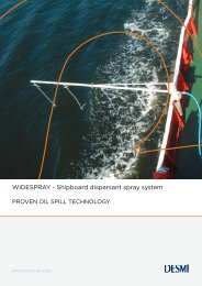
The <strong>DESMI</strong>-<strong>TARANTULA</strong> combination skimmer system is the new generation of<br />
<strong>DESMI</strong>’s vertical Archimedes’ screw skimmers.<br />
The <strong>DESMI</strong>-<strong>TARANTULA</strong> combination skimmer is a high capacity light-weight ocean<br />
skimmer which skims 250 m3/h with up to 200 mm automatic weir lip adjustment. It<br />
works efficiently in waves heights up to 3 metres.<br />
The skimmer combination skimmer system consists of a WEIR skimmer, a BRUSH<br />
DRUM skimmer and a DISC skimmer which means that the skimmer is very<br />
efficiency in all kinds of oil spills.<br />
It is very easy to change between the different type of skimmers.<br />
The use of only a few parts makes it a simple skimmer, easy to assemble and easy<br />
to maintain, resulting in low weight and high buoyancy/seaworthiness.<br />
Using two <strong>DESMI</strong> modified positive displacement Archimedes' screw pumps in<br />
vertical design, type DOP-250, the <strong>DESMI</strong>-<strong>TARANTULA</strong> combination skimmer is<br />
able to efficiently recover light as well as heavy oil, also when mixed with debris<br />
normally found in connection with oil spills.<br />
The skimmer is fitted with a flotation system to provide the necessary buoyancy.<br />
Hydraulic power to the skimmer pumps is supplied through hydraulic hoses<br />
connected to the power supply or remote control box. A discharge hose connects the<br />
skimmer to the storage tank.<br />
The hoses will not affect the buoyancy of the skimmer as they are equipped with their<br />
own floats.<br />
The <strong>DESMI</strong>-<strong>TARANTULA</strong> skimmer is designed as an advancing skimmer to operate<br />
in conjunction with a floating containment boom. Do not start the skimmer pump<br />
before a sufficient oil layer is collected (<strong>DESMI</strong> recommends a minimum of 2 cm<br />
(3/4”)). The recovery efficiency may vary from 50 to 100% subject to oil quantity (oil<br />
layer thickness), oil viscosity, boom make, wave conditions, towing speed, and<br />
maybe most important: The operator’s skill!<br />
As an option the <strong>DESMI</strong>-<strong>TARANTULA</strong> skimmer is provided with two thrusters to<br />
secure the best recovery position in the floating containment boom. The thrusters are<br />
hydraulically driven and controlled from the remote control box.<br />
WARNING!<br />
This equipment is designed to cope with debris normally found in an oil spill, and<br />
can be dangerous if the safety precautions in this manual are not followed. Do<br />
not use the equipment without being familiar with the safety instructions. The<br />
customer is responsible for accidents caused by the equipment, if the safety<br />
instructions in this manual are not being followed.
2.0 TRANSPORTATION AND MOUNTING<br />
2.1 Transportation of the skimmer<br />
The <strong>DESMI</strong>-<strong>TARANTULA</strong> skimmer is equipped with a lifting eye for transportation of<br />
the assembled skimmer or for transportation of the pump section alone (see drawing<br />
no. 481741/43).<br />
CAUTION!<br />
Do not lift the skimmer in other parts than the lifting device or the carrying<br />
handles!<br />
Weight:<br />
Total: 550 kg<br />
2.2 Mounting (See drawing 481741/43)<br />
A. Remove from the container (OPTION) the pump section incl. hopper with weir<br />
lip and the four float pipes with the floats and the two thrusters.<br />
B. Snap on the float pipes with the floats to the pump section and be sure that the<br />
pipes are locked.<br />
C. Be sure that the drain hoses from the two DOP-250 pumps are connected to<br />
the drain couplings behind the coupling manifold<br />
.<br />
WARNING!<br />
Always keep a safety distance to the skimmer/pump of minimum 2 m/7 ft.<br />
when the skimmer/pump is connected to the hydraulic power supply. Do<br />
not connect the hydraulic hoses to the power supply until you are ready for<br />
operation.
3.0 RESPONSE TACTICS<br />
3.1. General remarks<br />
It is very difficult to generalise when discussing oil spill situations. Each spill has its<br />
own set of characteristics: Location, close to shore or far off shore, environmental<br />
sensitivity, shallow or deep water, waves, current, wind speed and direction,<br />
temperature, size of spill, type of oil, time after spill, debris, etc.<br />
However, there are common factors that influence how successful the clean-up<br />
operation will be, and they should all be incorporated in an appropriate contingency<br />
plan:<br />
Availability and capability of equipment (ships, skimmer systems, booms, pumps,<br />
storage tanks etc.) and maintenance of the same<br />
Availability of manpower, well trained/not trained<br />
What to protect first of all<br />
Communication<br />
Information<br />
Surveillance<br />
Command<br />
Strategy/planning<br />
Etc.<br />
Regarding the equipment described in this manual, the most important common<br />
factors for success are:<br />
Maintenance and<br />
Training<br />
NOTE!<br />
Training again and again is the only way to be sure to realise the full<br />
capacity of your <strong>DESMI</strong>-<strong>TARANTULA</strong> skimmer system. It is also critical to<br />
ensure proper preventative and corrective maintenance as described in this<br />
manual.<br />
3.2. Oil spills at sea<br />
An overflow weir skimmer should always be within sight of the operator. The closer<br />
the operator is to the skimmer, the better the control and recovery efficiency.
For best manoeuvrability use the skimmer(s) in a single or<br />
double sweep configuration with the skimmer(s) in the<br />
apex of the ship’s side sweep boom(s). For larger oil spills<br />
the configuration may be combined with “J” sweep(s) (Fig.<br />
3) which will feed oil into the system from a wider area.<br />
Use for instance towable storage bladders for storage.<br />
WIND WindDIRECTION<br />
direction<br />
As the ship moves forward through the water, the side<br />
sweeping booms concentrate the oil as the surface area<br />
within the sweep is reduced. This naturally increases the<br />
thickness of the oil layer. It is important that the ship<br />
maintains a constant speed of approximately 0.75 knots<br />
with most boom systems.<br />
Move through the slick and allow the oil layer to build up<br />
in the apex of the boom before starting the skimmer<br />
pump. We recommend an oil layer of at least 2 cm<br />
(3/4”) or more for best efficiency.<br />
Fig. 3 - J-configuration<br />
Try to minimise the total time that the oil is within the<br />
collection area before being skimmed in order to reduce<br />
the risk of oil escaping under the boom. If in doubt, it is always better to start<br />
skimming too early than too late. Any excess water is not a serious problem since the<br />
DOP-250 skimmer pumps do not emulsify the oil and water. The free water can<br />
easily be decanted from the storage tank or collapsible barge and pumped out in<br />
front of the collection sweep.<br />
Debris is a universal problem in almost all oil spill situations. However, the cutting<br />
knife on the inlet of the <strong>DESMI</strong> DOP-250 pumps will handle a lot of the debris<br />
normally found at a spill site: Seaweed, kelp, plastic bags, aluminium cans, bottles,<br />
dead birds, rope (up to 1/2”), wood (up to 1” pine dowel), etc.<br />
Larger debris, such a lumber, tree trunks, large branches, dead animals, etc. must be<br />
manhandled in most situations. One way is to pull it away from the skimmer after it<br />
enters the sweep. The best way is to deflect the bigger debris before it enters the<br />
containment boom. Various techniques exist such as having personnel located in a<br />
boat in front of the sweep, using rakes to pull away the debris.<br />
Deflecting debris may cause deflection of some oil as well. This is, however, far<br />
better than loosing all the oil contained in the boom due to damage or other<br />
complications caused by, for instance, a large tree branch.
4.0 OPERATION OF THE <strong>DESMI</strong>-<strong>TARANTULA</strong> WEIR SKIMMER<br />
WARNING!<br />
WHEN OPERATING: A safety distance to the skimmer/pump of minimum 2 m/7<br />
ft. must be observed by all personnel when the skimmer/pump is connected to<br />
the hydraulic power supply. Also when the skimmer/pump is not running.<br />
4.1 Operation principle (see drawing no. 481741/43)<br />
The <strong>DESMI</strong>-<strong>TARANTULA</strong> is an overflow weir type skimmer. It consists of the pump<br />
section, the four floats with connecting tubes and the hopper with the weir lip. The<br />
weir lip consists of a membrane with a ring-shaped float floating inside the hopper.<br />
On land the ring float on the weir lip will be in its lowest position due to the empty<br />
hopper. When the skimmer is being deployed the oil starts flowing over the weir lip<br />
and into the hopper. The ring float will begin floating on the oil in the hopper. The<br />
buoyancy will lift up the ring float, until the oil stops entering the hopper.<br />
As soon as the pumps start pumping (causing a lower oil level in the hopper), the ring<br />
will automatically adjust its vertical position downwards, allowing more oil to enter the<br />
hopper.<br />
At low pump RPM the ring float will float high inside the hopper, allowing only little oil<br />
to enter the skimmer. At higher RPM the pumps will remove the oil under the ring<br />
float, the float will thus obtain a lower position and more oil will enter the skimmer.<br />
The weir lip will automatically adjust its weir lip to the most optimal position at any<br />
recovery rate.<br />
Besides the up/down movement the weir lip is able to float independently of the<br />
skimmer due to its extremely low inertia mass, and the very flexible connection to the<br />
skimmer. This enables the ring float to keep its weir lip parallel to the oil/water<br />
interface even in small swells which the skimmer is not able to follow.
4.2 Before operation<br />
WARNING !<br />
Keep away from the rotating pump screw and cutting knife. The pump<br />
screw/cutting knives are designed for cutting debris normally found at oil spill<br />
sites and will also cut off fingers and other limbs.<br />
WARNING !<br />
Always keep a safety distance to the pump of minimum 2 m/7 ft. when the<br />
pump is connected to the hydraulic power supply. Do not connect the<br />
hydraulic hoses to the power supply until you are ready for operation.<br />
A. Operate the hydraulic power supply of the skimmer according to the operator’s<br />
manual delivered by the supplier of the hydraulic power source.<br />
B. Hose connections<br />
1. Connect the hydraulic hose set from power source to the remote control box.<br />
Connect the 10 m hydraulic hose set from the remote control box to the<br />
hydraulic manifold on the hose reel.<br />
2. Connect the hydraulic hoses from the hose reel to the quick couplings on the<br />
manifold on skimmer.<br />
3. Connect the discharge hose to the skimmer discharge flange.<br />
4. Check that the locking devices on the hydraulic quick couplings are locked.<br />
5. The hydraulic drain line must always be used.<br />
6. Operate the skimmer pumps DOP1 and DOP2 forward and reverse at low rpm<br />
to check rotation and that the pumps are working properly.<br />
7. Operate the thrusters forward and reverse to check that the thrusters are<br />
working properly.<br />
8. Launch the skimmer by means of the crane<br />
9. When deployed release the skimmer from the crane.<br />
10. After deployment of the skimmer and hoses connect the discharge hose to oil<br />
recovery tank.<br />
CAUTION!<br />
The pump should never run dry for more than a few seconds. Observe the<br />
safety distance of 2 m/7 ft.!
4.3 Operation<br />
WARNING !<br />
A safety distance to the skimmer/pump of minimum 2 m/7 ft. must be<br />
observed by all personnel when the skimmer/pump is connected to the<br />
hydraulic power supply. Also when the skimmer/pump is not running.<br />
NOTE!<br />
When pumping non-oily media (e.g. water during a training session), grease<br />
the plate wheel bearings every 8 hours of operation, using the grease nipple<br />
on the plate wheel shaft of the DOP-250 pumps.<br />
A. Place the skimmer by using the thrusters in the apex<br />
of the boom.<br />
The best recovery rate and efficiency are obtained<br />
when the skimmer is used in conjunction with an oil<br />
boom equipped with a U or V pocket at the apex (Fig.<br />
5). This enables the boom to concentrate even minor<br />
oil spills thus getting a thicker oil layer and more<br />
efficient skimming. Do not start the skimmer pump<br />
before a sufficient oil layer has been collected. <strong>DESMI</strong><br />
recommends an oil layer of at least 2 cm (3/4”) or<br />
more for the best efficiency.<br />
B. As soon as the oil layer has reached a minimum of 2<br />
Fig. 5 - U-formation with V-apex<br />
cm (3/4”) start the skimmer pump at low speed and<br />
increase pump speed gradually while monitoring the oil coming out of the<br />
discharge hose. Increase pump speed until too much water is coming with the oil<br />
out of the discharge hose, then decrease a little.<br />
If it is not possible to monitor the discharge hose adjust the pump speed so that<br />
the collected oil layer in the apex of the boom stays over 2 cm (3/4”).<br />
C. If the skimmer pump stops due to excessive debris/solids, simply reverse the<br />
pump to expel the blockage. Then restart the skimming operation.<br />
WARNING !<br />
If it is necessary to remove debris from the skimmer by hand, stop the<br />
skimming operation and disconnect the hydraulic hoses at the hydraulic<br />
power supply. For safety reasons always keep a distance to the skimmer of<br />
min. 2 m/7 ft. when the skimmer is connected to the hydraulic power supply.
Off-loading with the DOP-250 skimmer pump dismantled from the floats is<br />
described in the DOP Pump manual.<br />
4.4 Recovery after operation<br />
WARNING !<br />
Always keep a safety distance to the pump of minimum 2 m/7 ft. when the<br />
pump is connected to the hydraulic power supply.<br />
CAUTION !<br />
Take care that the discharge hose is not being sucked into the pump as this<br />
will result in severe damage to the hose.<br />
A. The contents of the discharge hose may be evacuated by reversing one of the<br />
skimmer pumps at low rpm.<br />
B. Start the recovery of the skimmer by reversing the hose reel. If necessary use the<br />
thrusters to place the skimmer in optimal position for recovery.<br />
C. If there is still any contents in the discharge hose while rewinding evacuate by<br />
reversing one of the skimmer pumps at low rpm.<br />
D. When the skimmer is in position close to the crane lift the skimmer from the water<br />
and on board the vessel.<br />
E. Follow the instructions in section 5.
5.0 INSPECTION AFTER OPERATION<br />
AND PREVENTATIVE MAINTENANCE<br />
NOTE !<br />
See DOP Pump manual for preventative and corrective maintenance.<br />
5.1. Clean the <strong>DESMI</strong>-<strong>TARANTULA</strong> skimmer<br />
WARNING !<br />
Keep away from the rotating pump screw and cutting knives. The pump<br />
screw/cutting knives are designed for cutting debris normally found at oil spill<br />
sites and will also cut off fingers and other limbs.<br />
Always keep a safety distance to the pump of minimum 2 m/7 ft. when the<br />
pump is connected to the hydraulic power supply.<br />
A. After the skimmer has been recovered connect the hydraulic hoses to the power<br />
supply and empty the DOP-250 pumps of oil and water. Disconnect the hydraulic<br />
hoses again and clean the complete skimmer with a solvent consistent with the<br />
medium skimmed.<br />
CAUTION !<br />
Do not use caustic cleaning solutions as this may damage aluminium parts.<br />
B. Wash the skimmer and thrusters with FRESH water. Connect the hydraulic hoses<br />
to the power supply and flush the DOP-250 pumps with fresh water letting the<br />
pump run slowly.<br />
C. Disconnect the hydraulic hoses and clean carefully all hydraulic quick couplings<br />
as well as the discharge coupling. Check for leaks and tighten up if necessary.<br />
5.2 Inspection of the DOP-250 pump<br />
A. Snap off the float pipes with the floats from the pump section by pulling the eyes<br />
on the locking devices.<br />
B. Disconnect the hydraulic hoses incl. quick couplings from the manifold on<br />
skimmer foot. Dismantle the skimmer foot and unscrew the hopper part from the<br />
pumps. The pumps are now ready for inspection after operation according to the<br />
pump manual.
5.3 Protection of the <strong>DESMI</strong>-<strong>TARANTULA</strong> skimmer<br />
A. After inspection of the pumps: Reassemble the pumps on the hopper flange and<br />
mount the foot on the pumps.<br />
B. Lubricate all quick couplings using anti-corrosion oil and fit the dust caps and<br />
dust plugs on all couplings.<br />
C. Store the skimmer in a dry place free of dust. The skimmer should be wrapped in<br />
plastic or by other means protected from a dusty environment when not in use.<br />
D. Protect the skimmer against sunlight. The bellows on the weir lip may be<br />
damaged after long time exposure to sunlight.<br />
5.4. Preventative maintenance of <strong>DESMI</strong>-<strong>TARANTULA</strong> floatation system<br />
A. Very little effort is necessary to keep the floatation system in the necessary state<br />
of readiness that is required for all oil spill recovery equipment. Follow the<br />
directions given in Section 5.1.<br />
B. Inspect all surfaces for possible damage due to collision with for instance the<br />
recovery vessel. Check the floats and float tubes for leaks. (Water in the float or<br />
tube will indicate a leak). The floats are made of oil resistant polyethylene plastic<br />
which is almost shockproof, but nevertheless damage is possible. If a leak is<br />
detected contact your local RO-CLEAN <strong>DESMI</strong> representative for repair.<br />
C. Check the O-sealing rings in the hydraulic quick couplings. Replace them if they<br />
look worn out. Keep the couplings clean. Dirt may affect the functioning of the<br />
couplings and the hydraulic system. Always use dust caps and dust plugs.<br />
D. Check the lifting device. It must be safely secured to the hopper.<br />
E. Check the locking devices that lock the float pipes to the pump.<br />
F. Check that the bellows on the weir lip is in good condition. Protect the weir lip<br />
against sunlight during storage.
6.0 TROUBLESHOOTING<br />
NOTE !<br />
For troubleshooting of the pump refer to the pump manual section 6.0.<br />
Problem<br />
The weir lip will not<br />
adjust properly<br />
The skimmer recover<br />
too much water<br />
Oil will not flow into the<br />
hopper<br />
Probable cause<br />
Water too shallow<br />
Viscosity of oil is<br />
extremely high and oil<br />
layer is very thick<br />
Too small oil layer<br />
Pumping is too fast<br />
compared to the<br />
available amount of oil<br />
Debris prevents the oil<br />
from entering the<br />
hopper<br />
The oil is very waxy.<br />
Behaves like ice flakes<br />
Action<br />
Move to deeper water, or if on<br />
the shore line:<br />
Dig a hole under the skimmer<br />
Dismantle the DOP-250 pump<br />
from the floats and use it fully<br />
submerged<br />
Stop skimming. Collect and<br />
concentrate more oil in the<br />
apex of the boom before<br />
restarting<br />
Slow down pump RPM, see<br />
just above.<br />
Check for leaks in the WLA<br />
Use the thrusters to secure<br />
the most effective recovery<br />
position in the floating<br />
containment boom<br />
Clear away debris<br />
Help feeding the skimmer<br />
using rakes etc. and<br />
concentrate more oil for the<br />
skimmer to work in
7.0 TECHNICAL SPECIFICATIONS FOR <strong>DESMI</strong> SKIMMER<br />
<strong>TYPE</strong> <strong>DESMI</strong>-<strong>TARANTULA</strong><br />
Dimensions:<br />
Draft:<br />
Weight (dry):<br />
Length:<br />
Width:<br />
Height:<br />
850 mm<br />
550 kg<br />
2950 mm<br />
2950 mm<br />
1690 mm<br />
Skimmer pump:<br />
Max. recovery rate:<br />
Max. pressure:<br />
2 pcs. DOP-250 vertical positive displacement<br />
Archimedes’ screw type. For details see DOP-250<br />
pump manual<br />
250 m 3 /h at 1 bar<br />
10 bar<br />
Materials: DOP-250 pump: See DOP-250 pump<br />
manual<br />
Floats, hopper and<br />
floating collar:<br />
Bellows:<br />
Float pipes:<br />
Other parts:<br />
Oil resistant polyethylene<br />
plastic (PE-HD)<br />
Chemically resistant PVC<br />
Stainless steel<br />
Stainless steel and<br />
seawater resistant<br />
aluminium<br />
Coating: Pump: Primer/company paint
7.1 Parts list 682575 for Tarantula<br />
Drawing Number 481741<br />
Pos. Item No. Description Qty.<br />
01 681473 <strong>DESMI</strong> DOP/250 - Dual pump 2<br />
02 184095 Foot 1<br />
05 183771 Floating pipe 4<br />
06 184135 Spacer 4<br />
07 184620 Adapter flange 1<br />
08 681987 Hopper 1<br />
09 181688 Bellows 1<br />
10 181844 Fastening rail 12<br />
11 181848 Ring for bellows 2<br />
12 181670 Inlet float ring 1<br />
13 183769 Float 4<br />
14 183629 Top cover for float 4<br />
15 183576 Discharge manifold 1<br />
16 681984 Lifting device 1<br />
19 181946 6“ discharge flange 1<br />
20 703732 CH-screw M8x 25 A4 16<br />
20 704066 Washer M8 A4 16<br />
21 184622 Coupling panel 1<br />
22 183869 Distance pipe 8<br />
22 183870 Protection grid 2<br />
22 704066 Washer M8 8<br />
22 705255 Hex screw M8x 35 A4 8<br />
23 703376 Hex screw M16x 50 A4 6<br />
23 704033 Washer M16 12<br />
23 710380 Locking Nut M16 6<br />
27 704012 Washer M10 8<br />
28 703232 Locking Nut M12 2<br />
28 704067 Washer M12 4<br />
28 705257 Hex screw M12x 45 A4 2<br />
29 182258 Pin ø10x50 8<br />
30 712392 Locking pin 8<br />
32 703232 Locking Nut M12 4<br />
32 704067 Washer M12 8<br />
32 705257 Hex screw M12x 45 A4 4<br />
33 704033 Washer M16 24<br />
33 708676 Hex screw M16x 65 A4 12<br />
33 710380 Locking Nut M16 12<br />
41 184360 Gasket for hopper 1<br />
42 183867 Gasket for DOP-250 pump 2<br />
44 705184 Dust plug 1” TEMA 2<br />
44 711365 Quick coupling 1" TEMA female 2
Pos. Item No. Description Qty.<br />
44 705455 Dust cap 1” TEMA 2<br />
44 711430 Bonded seal 1" 4<br />
47 713468 Ball valve 1<br />
48 708139 Plug 3/8” 2<br />
55 183874 Coupling adapter 1<br />
56 711357 Quick coupling 3/8” TEMA male 1<br />
56 711356 Quick coupling 3/8” TEMA female 2<br />
56 703619 Dust cap 3/8” TEMA 1<br />
56 711439 Bonded seal 3/8" 1<br />
59 711871 Hydr.hose 3/8” length 550mm 1<br />
62 703330 Nipple 3/8” BSP 3<br />
63 704389 Washer M6 84<br />
63 706893 Locking Nut M6 84<br />
63 708996 BH-screw M6 x 2 A4 84<br />
68 710611 Rubber fender 5m<br />
80 181348 Bulk head 1” x ¾” 4<br />
80 705989 Counter nut ¾” BSP 4<br />
94 705187 Bulk head 3/8” 1<br />
104 703641 Nipple 3/4” BSP 4<br />
108 703330 Nipple 3/8” BSP 4<br />
109 703331 Socket 3/8” BSP 2<br />
110 705113 Check valve 5 bar 1<br />
111 705115 Fitting GE12LR-1/4” 1<br />
117 703636 Bonded seal 3/4" 4<br />
120 703650 Bonded seal 3/8" 2<br />
121 703637 Bonded seal 1” 4<br />
124 706434 Drain pipe ø12x1 1
7.2 Parts list 682580 for Tarantula with thrusters<br />
Drawing Number 481743<br />
Pos. Item No. Description Qty.<br />
01 681473 <strong>DESMI</strong> DOP/250 - Dual pump 2<br />
02 184095 Foot 1<br />
05 183771 Floating pipe 4<br />
06 184135 Spacer 4<br />
07 184620 Adapter flange 1<br />
08 681987 Hopper 1<br />
09 181688 Bellows 1<br />
10 181844 Fastening rail 12<br />
11 181848 Ring for bellows 2<br />
12 181670 Inlet float ring 1<br />
13 183769 Float 4<br />
14 183629 Top cover for float 4<br />
15 183576 Discharge manifold 1<br />
16 681984 Lifting device 1<br />
19 181946 6“ discharge flange 1<br />
20 703732 CH-screw M8x 25 A4 16<br />
20 704066 Washer M8 A4 16<br />
21 184622 Coupling panel 1<br />
22 183869 Distance pipe 8<br />
22 183870 Protection grid 2<br />
22 704066 Washer M8 8<br />
22 705255 Hex screw M8x 35 A4 8<br />
23 703376 Hex screw M16x 50 A4 6<br />
23 704033 Washer M16 12<br />
23 710380 Locking Nut M16 6<br />
27 704033 Washer M16 4<br />
27 760225 Hex screw M16x 35 A4 4<br />
28 703232 Locking Nut M12 2<br />
28 704067 Washer M12 4<br />
28 705257 Hex screw M12x 45 A4 2<br />
29 182258 Pin ø10x50 8<br />
30 712392 Locking pin 8<br />
31 682178 Thrusters 2<br />
32 703232 Locking Nut M12 4<br />
32 704067 Washer M12 8<br />
32 705257 Hex screw M12x 45 A4 4<br />
33 704033 Washer M16 24<br />
33 708676 Hex screw M16x 65 A4 12<br />
33 710380 Locking Nut M16 12<br />
40 711356 Quick coupling 3/8” TEMA female 2<br />
41 184360 Gasket for hopper 1
Pos. Item No. Description Qty.<br />
42 183867 Gasket for DOP-250 pump 2<br />
44 705184 Dust plug 1” TEMA 2<br />
44 711365 Quick coupling 1" TEMA female 2<br />
44 705455 Dust cap 1” TEMA 2<br />
44 711430 Bonded seal 1" 4<br />
47 713468 Ball valve 1<br />
48 708139 Plug 3/8” 2<br />
55 183874 Coupling adapter 1<br />
46 711366 Quick coupling 1” TEMA male 2<br />
56 711357 Quick coupling 3/8” TEMA male 1<br />
56 711356 Quick coupling 3/8” TEMA female 2<br />
56 703619 Dust cap 3/8” TEMA 1<br />
56 711439 Bonded seal 3/8" 1<br />
62 703330 Nipple 3/8” BSP 3<br />
63 704389 Washer M6 84<br />
63 706893 Locking Nut M6 84<br />
63 708996 BH-screw M6 x 2 A4 84<br />
68 710611 Rubber fender 5m<br />
80 181348 Bulk head 1” x ¾” 4<br />
80 705989 Counter nut ¾” BSP 4<br />
94 705187 Bulk head 3/8” 1<br />
104 703641 Nipple 3/4” BSP 4<br />
108 703330 Nipple 3/8” BSP 4<br />
109 703331 Socket 3/8” BSP 2<br />
110 705113 Check valve 5 bar 1<br />
111 705115 Fitting GE12LR-1/4” 1<br />
117 703636 Bonded seal 3/4" 4<br />
120 703650 Bonded seal 3/8" 2<br />
121 703637 Bonded seal 1” 4<br />
124 706434 Drain pipe ø12x1 1
8.0 DRAWINGS<br />
8.1 Assembling, mounting and transportation no. 481741<br />
8.2 Assembling, mounting and transportation no. 481743
9.0 THRUSTERS - Part No. 682178<br />
Pos. Nos. refer to Drawing No. 481577<br />
Pos. No. PART No. DESCRIPTION<br />
QTY.<br />
01 712147 Propeller ø185 2<br />
02 712146 Hydraulic motor 2<br />
03 183340 Shaft 2<br />
04 183720 Thruster tube 2<br />
05 183722 Rail 2<br />
06 183337 Screen 1 2<br />
07 183338 Screen 2 2<br />
09 182258 Pin ø10x50 2<br />
10 712392 Locking pin 2<br />
11 700835 Sealing ring 2<br />
12 711341 O-ring 2<br />
13 704394 Chain 0,4m<br />
14 706070 Shackle 4<br />
15 1833480 Pointed screw M5 x 6 4<br />
16 1852620 CH-screw M5 x 12 A4 2<br />
17 704367 CH-screw M8 x 20 A4 8<br />
17 705450 Self-locking nut M8 8<br />
18 1848097 CH-screw M6 x 35 A4 6<br />
19 704389 Washer M6 16<br />
19 705002 CH-screw M6 x 12 A4 16<br />
20 711355 Hydr. Coupling ½” Tema male 2<br />
20 711354 Hydr. Coupling ½” Tema female 2<br />
20 708034 Dust cap ½” 2<br />
20 706477 Dust plug ½” 2<br />
20 711428 Bonded seal ½” 4<br />
21 711357 Hydr. Coupling 3/8” Tema male 2<br />
21 713619 Dust cap 3/8” 2<br />
21 711439 Bonded seal 3/8” 2<br />
27 706185 Nipple 1/8 x ¼” BSP 2<br />
28 703330 Nipple 3/8” BSP 7<br />
29 703650 Bonded seal 3/8” 7<br />
30 183790 Bracket 2<br />
31 703135 Self-locking nut M10 2<br />
31 704003 Washer M10 4<br />
31 705258 Hex.screw M10 x 35 A4 2<br />
32 704390 Plug ¼” BSP 2