Phase Noise - Adler Instrumentos
Phase Noise - Adler Instrumentos
Phase Noise - Adler Instrumentos

Create successful ePaper yourself
Turn your PDF publications into a flip-book with our unique Google optimized e-Paper software.
quency. The beat signal between the DUT and reference is used to<br />
measure the demodulation factor of the phase detector using multiple<br />
techniques allowing non-linear operation of the detector.<br />
Loop bandwidth and reference FM deviation (or tune slope) will be<br />
adjusted depending on the expected noise and stability of the DUT.<br />
For most of PLL and synthesizers a few hundred Hz is an average<br />
convenient value. Then, closing the loop, the reference source will be<br />
phase locked on the DUT signal and RF/LO phase detector inputs<br />
will be set automatically in phase quadrature, providing at the output<br />
of the detector the combined phase noise of the DUT and the reference.<br />
The bar graph located on the lock control module will allow a<br />
quick visual check of the loop status (the bar graph should be centered<br />
and steady). When the reference's phase noise is 6 dB better<br />
than the DUT's, its contribution to the detected noise is 1 dB only.<br />
The LNA, with auto-gain feature, will adjust the noise level to the<br />
optimum dynamic range of the digitizing board housed into the controller.<br />
The FFT calculation process is done in the computer and displayed<br />
on the monitor (not represented on the diagram). Loop bandwidth<br />
is fully compensated to display phase noise down to 1 Hz from<br />
the carrier.<br />
In PLL measurements, the system residual noise, or noise floor, will<br />
be the reference oscillator's phase noise.<br />
The PN9500 measures peak to peak jitter using internal and/or<br />
external band-pass filters. The user can also compute a real RMS<br />
value or a PP estimate based on a phase noise measurement using<br />
customizable masks.<br />
PN9500 Base System Specifications<br />
Frequency Input Range 2 MHz to 1.8 GHz<br />
Offset Analysis<br />
1 Hz to 1 MHz (options to<br />
40 or 500 MHz)<br />
Measurement Accuracy ±2 dB up to 1 MHz offset<br />
±3 dB up to 100 MHz offset<br />
±5 dB up to 500 MHz offset<br />
Reference Tuning Voltage<br />
<strong>Phase</strong> Lock Loop Gain<br />
±20 Volt with 5 mV resolution<br />
Proportional and Integral (DUT drift<br />
compensation)<br />
Parameters Standard RF High Level RF<br />
Frequency range, GHz 0.002 to 1.8 0.002 to 1.6<br />
RF Input min. dBm - 10 with input amplifier +10<br />
RF input max. dBm +10 +20<br />
LO input min. dBm 0 with input amplifier +10<br />
LO input max. dBm +15 +20<br />
RF input Gain, dB 0, 10 None<br />
LO input Gain, dB 0, 10 None<br />
<strong>Noise</strong> floor in dBc/Hz for a<br />
100 MHz RF input * RF = +9 dBm RF = +16 dBm<br />
LO = +13 dBm<br />
LO = +20 dBm<br />
1 Hz offset - 135 - 140<br />
10 Hz - 145 - 150<br />
100 Hz - 155 - 160<br />
1 kHz - 165 - 170<br />
10 kHz - 168 - 178<br />
100 kHz to 500 MHz - 168 - 178<br />
<strong>Noise</strong> floor variation<br />
at 1 GHz (dB) +1 +4<br />
<strong>Noise</strong> floor variation<br />
at 1.6 GHz (dB) +3 +6<br />
Recommended RF<br />
input level, dBm 0 to +10 dBm +10 to +17 dBm<br />
Recommended<br />
LO input level dBm +10 to +13dBm +17 to +20 dBm<br />
* For specified values add + 3 dB (± 2 dB accuracy). <strong>Noise</strong> floor: for<br />
RF power levels below specified value, the noise floor will increase by<br />
the number of dB below the specified value. For example, for +6 dBm<br />
RF input, instead of +9dBm, the typical system residual noise is, at<br />
10 kHz offset: -168 - (- 3 dB) = - 165 dBc/Hz.<br />
Maximum Offset (option)<br />
10 MHz for carriers up to 160 MHz<br />
40 MHz for carriers up to 400 MHz<br />
200 MHz for carriers up to 2 GHz<br />
500 MHz for carriers 2 GHz and above<br />
PN9500 Base System<br />
PN9500 mainframe including:<br />
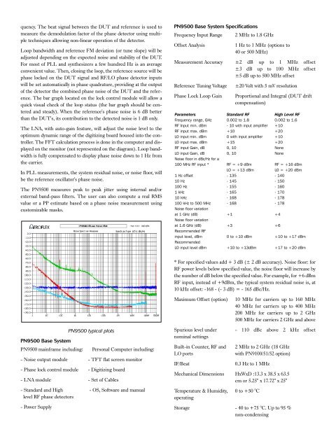
PN9500 typical plots<br />
Personal Computer including:<br />
- <strong>Noise</strong> output module - TFT flat screen monitor<br />
- <strong>Phase</strong> lock control module - Digitizing board<br />
- LNA module - Set of Cables<br />
- Standard and High - OS, Software and manual<br />
level RF phase detectors<br />
- Power Supply<br />
Spurious level under<br />
nominal settings<br />
Built-in Counter, RF and<br />
LO ports<br />
IF/Beat<br />
- 110 dBc above 2 kHz offset<br />
2 MHz to 2 GHz (18 GHz<br />
with PN9100/51/52 option)<br />
0.3 Hz to 1 MHz<br />
Mechanical Dimensions HxWxD :13.3 x 38.5 x 63.5<br />
cm or 5.25" x 17.72" x 25"<br />
Temperature & Humidity, 0 to +50 °C<br />
operating<br />
Storage - 40 to +75 °C. Up to 95 %<br />
non-condensing