Phase Noise - Adler Instrumentos
Phase Noise - Adler Instrumentos
Phase Noise - Adler Instrumentos

You also want an ePaper? Increase the reach of your titles
YUMPU automatically turns print PDFs into web optimized ePapers that Google loves.
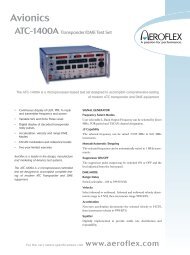
<strong>Phase</strong> <strong>Noise</strong><br />
PN9500 Wideband noise and jitter analyzer<br />
The PN9500 is the only available system capable of measuring state of the art<br />
phase noise up to 500 MHz offset.<br />
The Modular design of the PN9500 issued from<br />
the PN9000 product line provides versatility and<br />
flexibility to set up the appropriate configuration to<br />
measure any kind of frequency source from 2 MHz<br />
to 140 GHz.<br />
The PN9500 is the only available system capable of<br />
measuring state of the art phase noise up to<br />
500 MHz offset. But this feature is not the only<br />
unique feature of this RF & MW test set. Here is<br />
the combination that makes this system unique:<br />
• SPEED : 1 kHz to 40 MHz, 10 averages in<br />
less than 30 sec.<br />
• DYNAMIC RANGE : 0.001ps RMS on a<br />
10 GHz clock buffer<br />
• WIDE OFFSET : up to 500 MHz<br />
• TRUE Peak-to-Peak JITTER : selectable<br />
mask filters and peak to peak detector<br />
Plug-in optional module examples:<br />
Internal phase detectors up to 44 GHz<br />
Low <strong>Noise</strong> Built-in DC FM Reference MW Synthesizer<br />
The best MW down-converter for stable and free-running Sources<br />
mmW external harmonic mixers/diplexers to extend the frequency<br />
coverage up to 140 GHz<br />
Pulse generator and modulator<br />
Software:<br />
WPN9500: Windows based graphical user interface with file management<br />
and math tools<br />
The base system is the core of any measurement configuration. It<br />
includes hardware and software, except the reference source, to<br />
measure stable sources from 2 MHz to 1.8 GHz.<br />
PN9500 System - Basic Capabilities<br />
• EASE OF USE : “AUTO” Functions<br />
• MODULAR Plug-in System : compact and<br />
always upgradable<br />
The PN9500 is the ultimate testing machine when<br />
it comes to Jitter and <strong>Noise</strong> Analysis<br />
PN9500 Techniques:<br />
<strong>Phase</strong> Lock Loop, quadrature phase demodulation<br />
Delay line, FM discriminator (option)<br />
Added phase noise (option)<br />
Amplitude <strong>Noise</strong> (option)<br />
FFT for RMS and real PEAK-to-PEAK analog<br />
detectors combination in selectable filters<br />
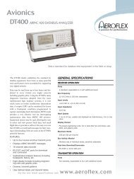
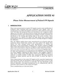
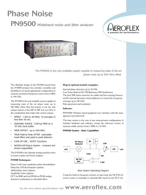
Base System Operating Diagram<br />
Using the built-in frequency counter, in open loop, the DC/FM reference<br />
source is manually or automatically tuned on the DUT fre-<br />
For the very latest specifications visit<br />
www.aeroflex.com
quency. The beat signal between the DUT and reference is used to<br />
measure the demodulation factor of the phase detector using multiple<br />
techniques allowing non-linear operation of the detector.<br />
Loop bandwidth and reference FM deviation (or tune slope) will be<br />
adjusted depending on the expected noise and stability of the DUT.<br />
For most of PLL and synthesizers a few hundred Hz is an average<br />
convenient value. Then, closing the loop, the reference source will be<br />
phase locked on the DUT signal and RF/LO phase detector inputs<br />
will be set automatically in phase quadrature, providing at the output<br />
of the detector the combined phase noise of the DUT and the reference.<br />
The bar graph located on the lock control module will allow a<br />
quick visual check of the loop status (the bar graph should be centered<br />
and steady). When the reference's phase noise is 6 dB better<br />
than the DUT's, its contribution to the detected noise is 1 dB only.<br />
The LNA, with auto-gain feature, will adjust the noise level to the<br />
optimum dynamic range of the digitizing board housed into the controller.<br />
The FFT calculation process is done in the computer and displayed<br />
on the monitor (not represented on the diagram). Loop bandwidth<br />
is fully compensated to display phase noise down to 1 Hz from<br />
the carrier.<br />
In PLL measurements, the system residual noise, or noise floor, will<br />
be the reference oscillator's phase noise.<br />
The PN9500 measures peak to peak jitter using internal and/or<br />
external band-pass filters. The user can also compute a real RMS<br />
value or a PP estimate based on a phase noise measurement using<br />
customizable masks.<br />
PN9500 Base System Specifications<br />
Frequency Input Range 2 MHz to 1.8 GHz<br />
Offset Analysis<br />
1 Hz to 1 MHz (options to<br />
40 or 500 MHz)<br />
Measurement Accuracy ±2 dB up to 1 MHz offset<br />
±3 dB up to 100 MHz offset<br />
±5 dB up to 500 MHz offset<br />
Reference Tuning Voltage<br />
<strong>Phase</strong> Lock Loop Gain<br />
±20 Volt with 5 mV resolution<br />
Proportional and Integral (DUT drift<br />
compensation)<br />
Parameters Standard RF High Level RF<br />
Frequency range, GHz 0.002 to 1.8 0.002 to 1.6<br />
RF Input min. dBm - 10 with input amplifier +10<br />
RF input max. dBm +10 +20<br />
LO input min. dBm 0 with input amplifier +10<br />
LO input max. dBm +15 +20<br />
RF input Gain, dB 0, 10 None<br />
LO input Gain, dB 0, 10 None<br />
<strong>Noise</strong> floor in dBc/Hz for a<br />
100 MHz RF input * RF = +9 dBm RF = +16 dBm<br />
LO = +13 dBm<br />
LO = +20 dBm<br />
1 Hz offset - 135 - 140<br />
10 Hz - 145 - 150<br />
100 Hz - 155 - 160<br />
1 kHz - 165 - 170<br />
10 kHz - 168 - 178<br />
100 kHz to 500 MHz - 168 - 178<br />
<strong>Noise</strong> floor variation<br />
at 1 GHz (dB) +1 +4<br />
<strong>Noise</strong> floor variation<br />
at 1.6 GHz (dB) +3 +6<br />
Recommended RF<br />
input level, dBm 0 to +10 dBm +10 to +17 dBm<br />
Recommended<br />
LO input level dBm +10 to +13dBm +17 to +20 dBm<br />
* For specified values add + 3 dB (± 2 dB accuracy). <strong>Noise</strong> floor: for<br />
RF power levels below specified value, the noise floor will increase by<br />
the number of dB below the specified value. For example, for +6 dBm<br />
RF input, instead of +9dBm, the typical system residual noise is, at<br />
10 kHz offset: -168 - (- 3 dB) = - 165 dBc/Hz.<br />
Maximum Offset (option)<br />
10 MHz for carriers up to 160 MHz<br />
40 MHz for carriers up to 400 MHz<br />
200 MHz for carriers up to 2 GHz<br />
500 MHz for carriers 2 GHz and above<br />
PN9500 Base System<br />
PN9500 mainframe including:<br />
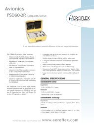
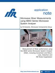
PN9500 typical plots<br />
Personal Computer including:<br />
- <strong>Noise</strong> output module - TFT flat screen monitor<br />
- <strong>Phase</strong> lock control module - Digitizing board<br />
- LNA module - Set of Cables<br />
- Standard and High - OS, Software and manual<br />
level RF phase detectors<br />
- Power Supply<br />
Spurious level under<br />
nominal settings<br />
Built-in Counter, RF and<br />
LO ports<br />
IF/Beat<br />
- 110 dBc above 2 kHz offset<br />
2 MHz to 2 GHz (18 GHz<br />
with PN9100/51/52 option)<br />
0.3 Hz to 1 MHz<br />
Mechanical Dimensions HxWxD :13.3 x 38.5 x 63.5<br />
cm or 5.25" x 17.72" x 25"<br />
Temperature & Humidity, 0 to +50 °C<br />
operating<br />
Storage - 40 to +75 °C. Up to 95 %<br />
non-condensing
PN9500 typical phase and amplitude detector options<br />
specifications<br />
Parameters MW (option) MW (option) MW (option) AM (option)<br />
Std level High level PN9361-02<br />
Frequency range,<br />
GHz 1.6 to 26.5 1.6 to 26.5 5 to 40 GHz 0.01 to 26.5<br />
RF Input min. dBm - 10 +10 0 0<br />
RF input max. dBm +15 +20 +15 +19<br />
LO input min. dBm +7 +10 +7 None<br />
LO input max. dBm +15 +23 +15 None<br />
<strong>Noise</strong> floor *,<br />
in dBc/Hz at RF = +6 dBm RF = +16 dBm RF = +6 dBm RF = +17<br />
LO = +10 dBm LO = +20 dBm LO = +10 dBm dBm<br />
1 Hz offset - 120 - 128 - 120 NA<br />
10 Hz - 130 - 138 - 130 NA<br />
100 Hz - 140 - 148 - 140 - 142<br />
1 kHz - 150 - 158 - 150 - 150<br />
10 kHz - 160 - 168 - 160 - 160<br />
100 kHz to<br />
500 MHz - 168 - 174 - 168 - 160<br />
Recommended RF<br />
input level, dBm 0 to +10 +10 to +16 0 to +10 +10 to +17<br />
Recommended LO<br />
input level, dBm +10 to +13 +17 to +20 + 10 to +13 NA<br />
* For specified values add +3dB (±2 dB accuracy). <strong>Noise</strong> floor: for<br />
RF power levels below specified value, the noise floor will increase by<br />
the number of dB below the specified value. For example, for +3 dBm<br />
RF input, instead of +6 dBm, the typical system MW residual noise<br />
is, at 10 kHz offset: -160 - (-3 dB) = - 157 dBc/Hz.<br />
WPN9500 Software<br />
The Windows software provides a friendly interface to the system<br />
ADDED NOISE added noise for two port devices<br />
PULSE for pulsed sources or pulsed two ports devices (PM, AM,<br />
Added noise)<br />
Photographic based cabling helps to guide the user in wiring settings.<br />
System configuration, file management, phase detector, frequency<br />
range, down-converter, selections<br />
Store and display up to ten measurements or specification lines with<br />
direct access memories. Plot export as TXT, BMP, JPEG or PNG file<br />
to any windows accessible storage device.<br />
Measurement mode - Automatic and Manual<br />
Automated Measurements are based on embedded expertise that<br />
guides the user through the measurement process. In most of the<br />
cases, a single click is enough.<br />
Manual Measurement for reference LO selection and tuning, phase<br />
detector calibration factor measurement, loop bandwidth and<br />
reference tune slope, reference phase locking<br />
Data processing<br />
<strong>Noise</strong>/Spurious<br />
differentiation<br />
Display functions<br />
Data Computation<br />
Integrated power<br />
Spurs expressed and displayed in dBc<br />
Smooth, spec-line, frequency & level<br />
markers, spurs list<br />
A±B, N*A, A:N, A±N*B, A±NdB<br />
in dBc, radian rms, radian², degree<br />
rms, degree², Hz rms, Hz²<br />
Variance<br />
Jitter<br />
FFT / Spectrum Analysis<br />
Plot Printing<br />
External synthesizer driver<br />
Allan, True, Modified and Tvar<br />
Sec rms ,Sec pp , UI pp<br />
L(f) dBc/Hz, Power dBv 2 /Hz, M(f)<br />
dBc/Hz<br />
Any windows supported printer<br />
User defined IEEE-488 control menu<br />
to set up most of commercial signal<br />
generators<br />
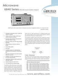
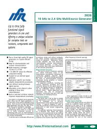
WPN9500 typical screenshot<br />
Measurement method control<br />
Selection of measurement method, depending on the DUT:<br />
PLL Synth for internal or GPIB controlled reference synthesizer<br />
method (for stable sources)<br />
PLL Xtal for DC-FM controlled sources like crystal oscillators<br />
VCO (delay line) for free running sources<br />
AM noise<br />
PN9500 Jitter Tool box<br />
<strong>Noise</strong> voltage for voltage sources<br />
For the very latest specifications visit<br />
www.aeroflex.com
CHINA<br />
Tel: [+86] (21) 6282 8001<br />
Fax: [+86] (21) 6282 8002<br />
EUROPE<br />
Tel: [+44] (0) 1438 742200<br />
Fax: [+44] (0) 1438 727601<br />
FRANCE<br />
Tel: [+33] 1 60 79 96 00<br />
Fax: [+33] 1 60 77 69 22<br />
HONG KONG<br />
Tel: [+852] 2832 7988<br />
Fax: [+852] 2834 5364<br />
SCANDINAVIA<br />
Tel: [+45] 9614 0045<br />
Fax: [+45] 9614 0047<br />
SPAIN<br />
Tel: [+34] (91) 640 11 34<br />
Fax: [+34] (91) 640 06 40<br />
UNITED KINGDOM<br />
Tel: [+44] (0) 1438 742200<br />
Toll Free: [+44] (0800) 282 388 (UK only)<br />
Fax: [+44] (0) 1438 727601<br />
USA<br />
Tel: [+1] (316) 522 4981<br />
Toll Free: [+1] (800) 835 2352 (US only)<br />
Fax: [+1] (316) 522 1360<br />
As we are always seeking to improve our products,<br />
the information in this document gives only a general<br />
indication of the product capacity, performance and<br />
suitability, none of which shall form part of any contract.<br />
We reserve the right to make design changes<br />
without notice. All trademarks are acknowledged.<br />
Parent company Aeroflex, Inc. ©Aeroflex 2004.<br />
www.aeroflex.com<br />
info-test@aeroflex.com<br />
Our passion for performance is defined by three<br />
attributes represented by these three icons:<br />
solution-minded, performance-driven and customer-focused.<br />
Part No. 46891/173, Issue 1, 06/04